
AT A GLANCE:
General information
This section applies to anyone who lifts loads using the crane, performs work on the crane, or works nearby.
At the start
Using this product manual
The following symbols are used in this product manual:
- This is an instruction regarding an action and prompts you to perform a work step.
- This is the result of an action and describes what happens on the device.
- This is a list.
Only with...
A section that appears in a box framed by a dashed line is only applicable for certain types, versions or options. The condition to which the section applies is specified at the beginning in the heading “Only with...”.
Instructions for the product manual
Read the product manual through carefully before starting work. Also be sure to observe additional product manuals for accessories and components.
Afterwards, keep the product manual available in the vicinity of the crane. It must be accessible to all who work with or on the crane.
If the crane is sold on or hired out, always provide the product manual together with the crane.
Proper use
The wire rope hoist is intended for use on a correspondingly designed overhead travelling crane or wall travelling crane for area-wide movement of loads. The wire rope hoist therefore moves on an I-beam or a welded box girder.
- The wire rope hoist can travel on welded box girders.
- The wire rope hoist is intended for a trolley power supply using the ABUPowerline energy chain or an ABUS festoon cable system.
Regulations
The installation has been built and tested according to European standards, rules and regulations applicable at the time of its manufacture. The conventions applied during design and construction are specified in the Declaration of Conformity or the Declaration of Incorporation. The conventions must also be observed for installation, operation, inspection and maintenance, as must the applicable occupational health and safety regulations.
Which provision applies in individual cases will greatly depend on the crane’s use and the national regulations. Review and observe all applicable and current regulations, including the occupational health and safety regulations. Refer also to the Declaration of Conformity or Declaration of Incorporation.
Warranty
- ABUS assumes no liability for damages that were caused by improper use, inadequately trained personnel, incorrect performance of work, nor for any changes, reconstruction or other modification of the crane or crane components which were not approved by ABUS.
- Any warranty claim becomes invalid if components were modified without consent, the crane or crane components were installed, used or serviced in any way other than that described in this product manual, or if parts other than original ABUS replacement parts were used.
- Safe operation of the crane or crane components is only guaranteed if original ABUS replacement parts are used.
The wire rope hoist
Description of the device
Side-mounted trolley (S)
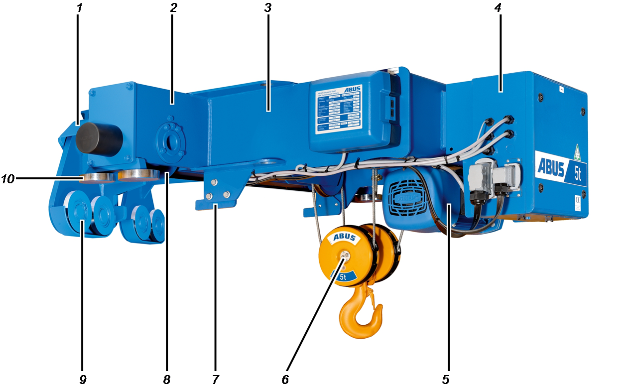
- 1: Bracket
- 2: End carriage
- 3:Trolley frame
- 4: Panel
- 5: Hoist drive
- 6: Bottom block and load hook
- 7: Lift-off prevention device
- 8: Hoist trolley
- 9: Supporting wheel
- 10: Guide roller
Performance features
The side-mounted trolley (S):
- The wire rope hoist is mounted on the upper flange of the crane. The trolley frame of the hoist thus runs on the main girder, which enables a larger hook path.
- The hoist trolley consists of two parts. The first part consists of an end carriage used by the wire rope hoist to run along the trolley track, which is welded onto the side of the main girder. The second part consists of a side frame with supporting wheels, with which the wire rope hoist grips the upper flange. The supporting wheels thus travel along the underside of the upper flange.
If a GM 800 hoist drive is installed, the wire rope hoist only has one side frame with supporting wheels. Otherwise, the wire rope hoist has two side frames with supporting wheels, which are mounted on a rocker on the bracket on the trolley frame.
- Often, the crane has an off-centre end carriage connection due to the torques which arise in the design.
- The wire rope hoist covers a load capacity range of 1 t to 10 t.
The trolley drive:
- The drives are designed as pole-variable rotary current motors with electromagnetic brakes and gear units.
- The drives have a low and a high speed. The ratio of the two speeds is 1:4.
- The drive's gear unit is a maintenance-free, two-stage or three-stage planetary gear.
The hoist drive with pole-variable hoist motor:
- The hoist drive is powered by a pole-variable 2/12-pole hoist motor with gear unit.
- The hoist motor features an electro-magnetically actuated spring-loaded brake.
- The hoist drive has a slow lifting speed and a fast lifting speed. The ratio of the two lifting speeds is 1:6.
- Using plug-in connections in the connector housing directly on the hoist drive, the hoist drive can be quickly separated from the rest of the crane’s electrics.
- The hoisting gear features a multi-stage, helical spur gear in an alloy housing. The gear wheels run in a sealed oil bath, which ensures they remain lubricated over their full service life.
- For further details on the pole-variable hoist drive, see the product manual “Pole-variable, modular ABUS hoist drive for wire rope hoists”.
The hoist:
- The wire rope of the hoist is a special wire rope with a very high breaking strength. This gives it a considerably longer service life than a normal steel rope.
- The cable guide guarantees flawless winding and unwinding of the wire rope on the cable drum. It is made of wearproof, low-friction plastic.
Technical data
Ambient conditions for operation:
Ambient temperature |
-10 °C to +40 °C |
Ambient temperature |
+40 °C to +65 °C |
Housing |
IP 55 |
Insulation class |
F |
Noise emissions:
Size |
Sound pressure level LP, m dB(A) at distance of 4 m |
Sound pressure level LW, m dB(A) |
|---|---|---|
GM 800 |
62 |
82 |
GM 1000 |
64 |
84 |
GM 2000 |
66 |
86 |
GM 3000 |
67 |
87 |
In the table, the sound pressure level LP is specified for a distance of 4 m from the wire rope hoist. To calculate the sound pressure level LW, the sound pressure level at any distance may be used.
Transporting the wire rope hoist on a lorry
Only with uninstalled wire rope hoists
Observe the following points, amongst others:
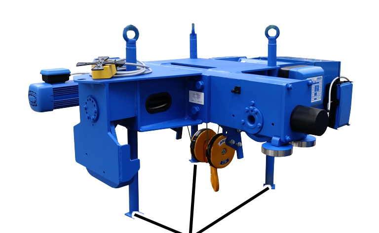
- Secure all loose parts and cables.
- Secure the load according to regional regulations.
- Secure the wire rope hoist to the loading area with suitable lifting tackle.
- Secure the load hook so that it cannot slide back and forth during transport.
- The cable guide holds the wire rope firmly against the cable drum. Thus, no loops can form on the cable drum and the wire rope is free of kinks.
Note
The transport supports may only be removed if the wire rope hoist is appropriately fixed and secured.
Loading and unloading the wire rope hoist
Only with uninstalled wire rope hoists
Observe the following points amongst others:
Lifting wire rope hoist with a crane
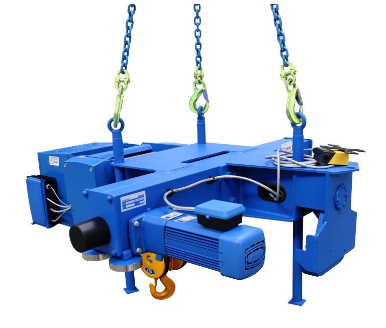
- Use suitable lifting tackle with load hooks.
- Insert the load hooks in the suspension eyelets on the transport supports on the wire rope hoist.
- Observe the occupational health and safety requirements and raise the wire rope hoist.
Setting down the wire rope hoist
- Setting the wire rope hoist down on the transport supports.
- Do not damage the bottom block when setting down.
Wire rope hoist disposal
If the wire rope hoist needs to be disposed of:
- Dismantle the wire rope hoist as far as is possible.
- Observe local regulations concerning disposal and recycling.
- Sort the individual parts by material and dispose of them in an environmentally sound manner.
- Dispose of oil and grease from the gear units as lubricants.
- Dispose of brake linings as multiple components (hazardous waste).
- Dispose of electronic components as scrap electronic parts.
- Dispose of cables, plug-in connections and pendant controls as scrap electronic parts.
- Dispose of the trolley frame, cable drum, deflection rollers, wire rope and other metal components as metal scrap.
- Dispose of the housing cover and housing base of the control as plastic waste.
- Parts of the wire rope hoist that have been repainted must be disposed of in accordance with the paint manufacturer’s specifications.

Installing and connecting
This section applies to anyone who works on the crane prior to its use
The end user of the crane is responsible for the proper qualifications of the commissioning personnel.
Examples of qualified persons:
- Persons with comprehensive knowledge from specialist training in engineering and in the electrical systems of cranes.
- Persons with sufficient experience in the operation, installation and maintenance of cranes.
- Persons with comprehensive knowledge regarding the relevant technical rules, directives and safety regulations applicable in the respective country.
- Persons receiving regular training from ABUS.
ABUS assumes no liability for damage due to incorrectly performed commissioning work done by unqualified personnel.
ABUS recommends having the commissioning work performed by the ABUS assembly team.
Checking the requirements
The following requirements must be met in order for the wire rope hoist to be installed:
Among other things, these points must be coordinated as part of the technical authorisation process:
- The welded box girder on which the wire rope hoist travels must meet the specifications of the enclosed dimension sheet and data sheet.
- The installation dimensions as well as the mains voltage and operating voltage must be correspondingly checked against the dimension sheet and the data sheet.
- The welded box girder on which the wire rope hoist travels must have a straight upper flange with straight trolley track.
- The running surface that the wheels of the wire rope hoist travel on must be free of paint or other coatings.
- The trolley power supply must be executed as ABUPowerline energy chain or ABUS festoon cable system.
Installing the wire rope hoist on the main girder
If the wire rope hoist has not been installed yet, continue here. Otherwise, skip this section.
If a GM 800 hoist drive is installed on the wire rope hoist, the wire rope hoist only has one side frame with supporting wheels. Otherwise, the wire rope hoist has two side frames with supporting wheels, which are mounted on a rocker.
In the following, the assembly is shown on a wire rope hoist with two side frames. The assembly with one side frame does not differ significantly.
Lifting the wire rope hoist onto the main girder
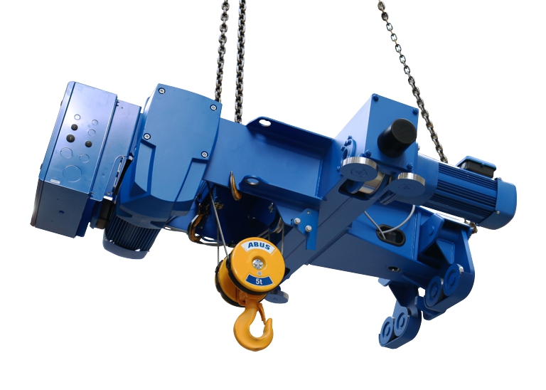
- Sling the wire rope hoist and lift it, e.g. with a truck-mounted crane.
- Remove the transport supports.
Wire rope hoist
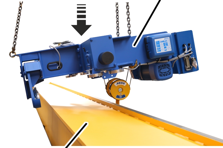
- Lower the wire rope hoist toward the main girder.
Bracket
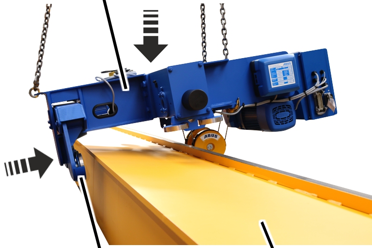
- Press the side frame with supporting wheels onto the main girder under the upper flange.
- Continue lowering the wire rope hoist.
BracketGuide roller
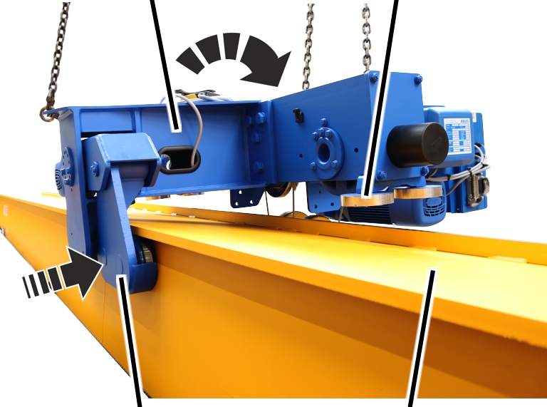
- Press the side frame with supporting wheels from below against the upper flange.
- Continue lowering the wire rope hoist and position the trolley tracks between the guide rollers.
When lowering, ensure that the guide rollers are not damaged and do not impact anything!
Guide roller
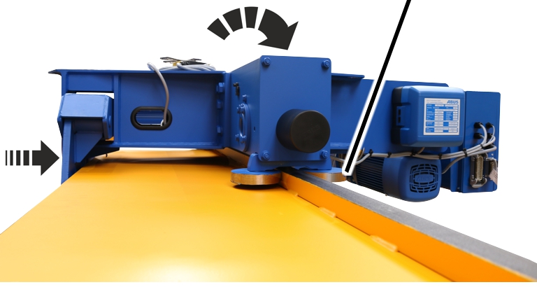
- Completely set down the wire rope hoist.
When lowering, ensure that the guide rollers are not damaged and do not impact anything!
If the wire rope hoist needs to be aligned:
In the following, the alignment is shown on a wire rope hoist with two side frames. The alignment with one side frame does not differ significantly.
Rib screwEccentric bolt
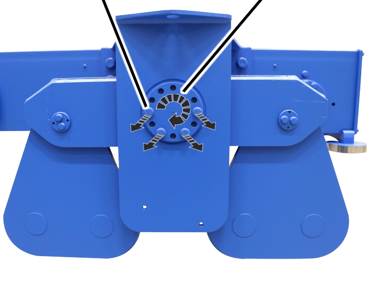
- Release the rib screws on the eccentric bolt.
- Align the wire rope hoist horizontally by turning the eccentric bolt.
Rib screwEccentric bolt
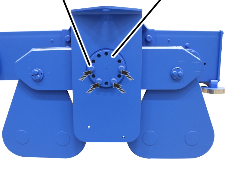
- Tighten the rib screws on the eccentric bolt.
Size |
Wheel Ø |
Rib screws |
Strength category |
Tightening torque |
|---|---|---|---|---|
GM 800 |
160 |
M8x25 |
10.9 |
42 Nm |
GM 1000 |
200 |
M10x25 |
10.9 |
75 Nm |
GM 2000 |
200 |
M10x25 |
10.9 |
75 Nm |
GM 3000 |
200 |
M10x25 |
10.9 |
75 Nm |
GM 3000 |
280 |
M12x25 |
10.9 |
115 Nm |
Installing the lift-off prevention device
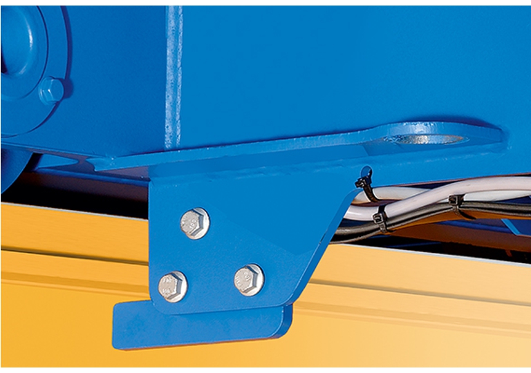
On both sides of the trolley frame:
Rib screw
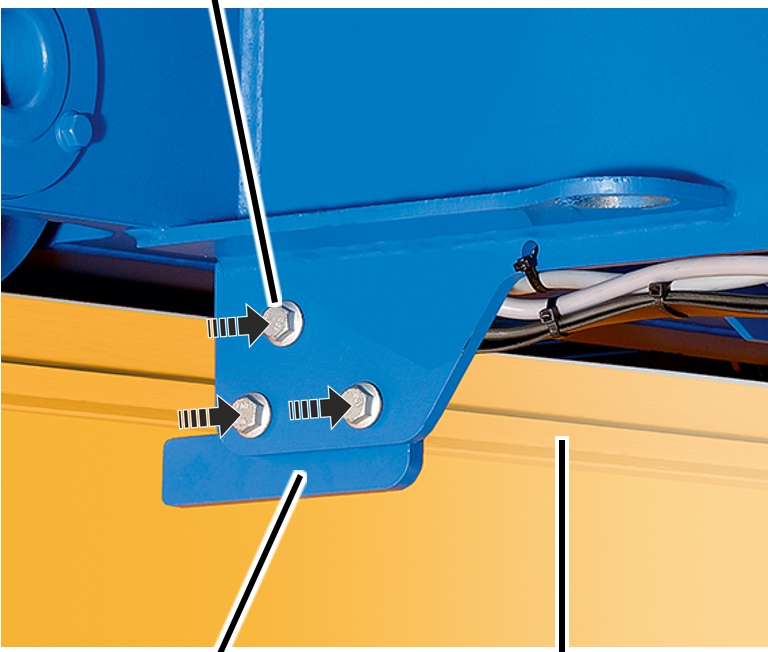
- Hold the lift-off prevention device to the trolley frame.
- Screw on the lift-off protection device tightly with rib screws (3x).
Rib screw |
Tightening torque |
|---|---|
M12x30 |
115 Nm |
M16x35 |
210 Nm |
Mounting the trolley towing arm
If the trolley towing arm has not been installed yet, continue here. Otherwise, skip this section.
The trolley towing arm is installed above the hoist panel. It pulls the electrical cables for the trolley power supply (festoon cable system or energy chain) and the cross-type limit switch of the trolley travel limit switch back and forth parallel to the trolley.
The trolley towing arm must be installed differently, depending on the main girder and the type of power supply (festoon cable system or energy chain).
Only with energy chains
Installing energy chain on carrying tube
The energy chain is fastened to the horizontal carrying tube.
Individual components of the energy chain
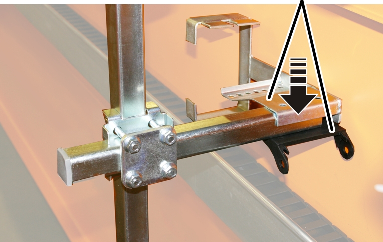
- Fasten the individual components of the energy chain (deflection bracket and connection element) with bolts and SL safety clip to the square tube.
Cable tiesFlat cable
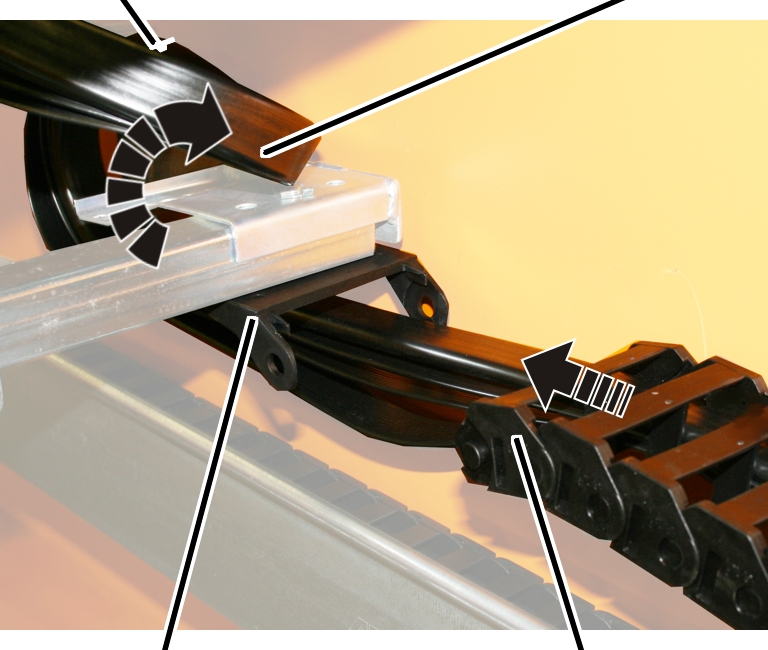
- Lead through the flat cable from the energy chain and guide in a curve around the deflection bracket.
- Fasten the flat cable with cable ties to the upper section of the deflection bracket.
- Insert the energy chain into the connection element and click into place.
Only with festoon cable system
Mounting the trolley towing arm
End carriages
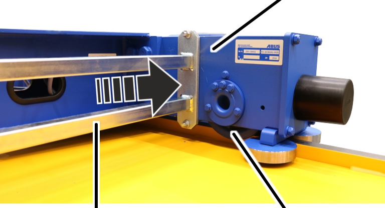
- Screw the trolley towing arm with the threaded bracket and M8 rib nuts to the end carriage. 15 Nm.
In doing this, make sure the wheel is not blocked.
Trolley towing arm
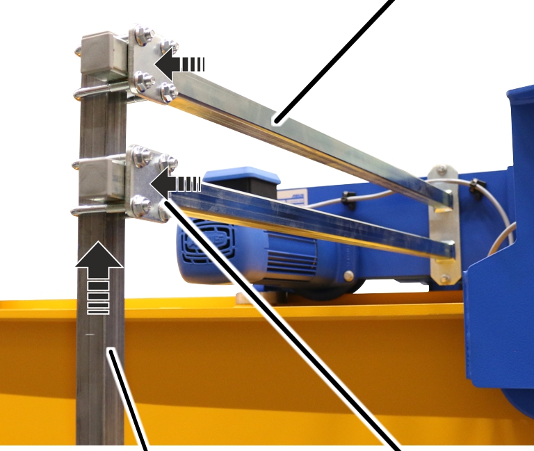
- Screw the square tube tightly to the trolley towing arm with the pipe clamps and M8 rib nuts. 15 Nm.
Vertical square tubeTowing trolley
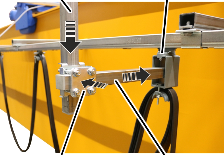
- Push the horizontal square tube into the towing trolley.
- Screw the horizontal square tube to the vertical square tube with pipe clamp and M8 rib nuts. 15 Nm.
Installing the cross-type limit switch
Only with cross-type limit switch
This section only applies if the wire rope hoist has a cross-type limit switch in the trolley travel direction.
Where and for which travel limit the cross-type limit switch is designed is specified on the wiring diagram.
Installing the cross-type limit switch
Locking washerHexagonal nut
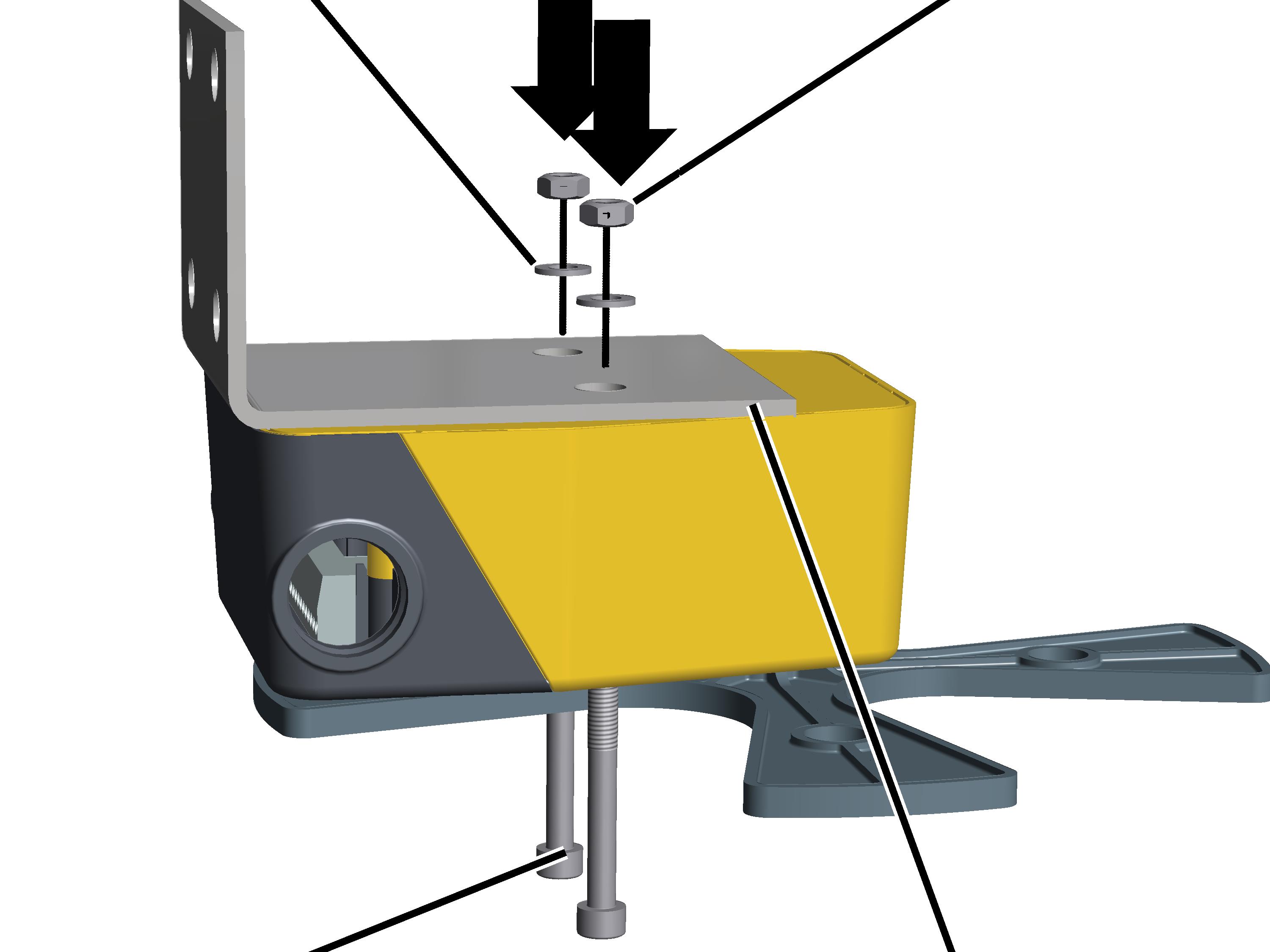
- Screw the mounting bracket onto the cross-type limit switch with the fillister-head screws M5x50 (2x).
- Screw on the mounting bracket using locking washers and M5 hex nuts (2x). 3 Nm.
Installing the cross-type limit switch on the trolley towing arm
The cross-type limit switch is installed either on the trolley towing arm or on the trolley frame. The installation on the trolley towing arm is shown here. The installation on the trolley frame does not differ significantly.
Trolley towing arm
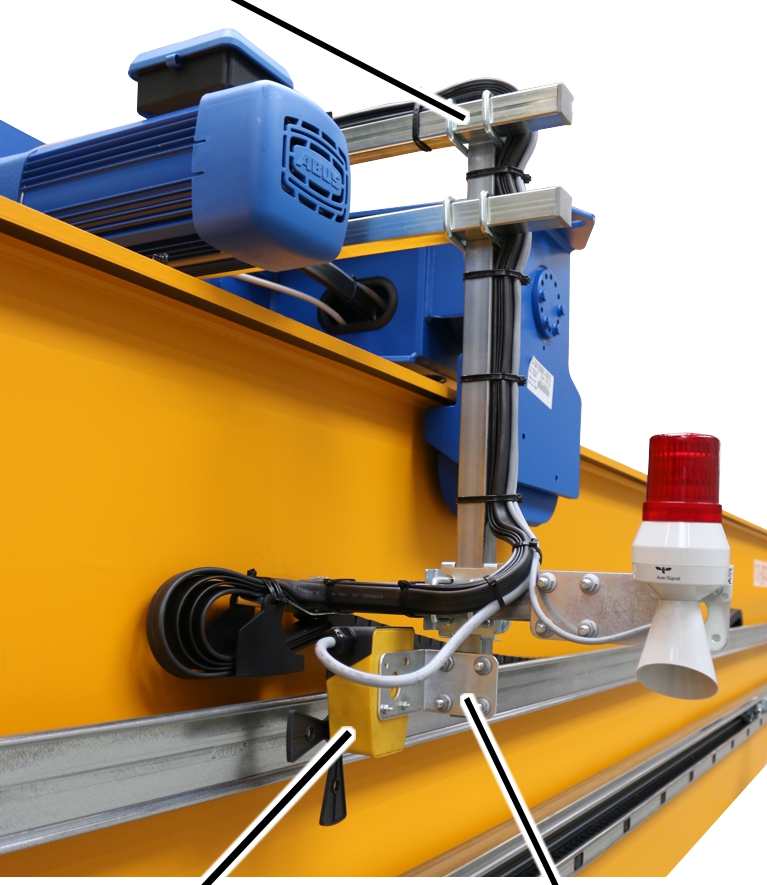
- Turn the cross-type limit switch to position 0.
- The position of the cross-type limit switch is marked with an arrow that can be rotated further, depending on the switching state.
- Attach the cross-type limit switch in such a way that the switching lug will activate it.
The rotation direction of the cross-type limit switch for the respective travel direction must match the wiring diagram.
- Screw on the cross-type limit switch. 15 Nm.
Connecting the cross-type limit switch
- Route the connection cable (round cable or flat cable) from the cross-type limit switch to the panel.
- Route the connection cable with cable fitting into the panel.
- If necessary: Connect the connection cable to a coupler plug or connector.
- Fasten connection cable with cable ties, cable grips and adhesive clips.
Installing the safety buffers
If the safety buffers are not yet installed, continue here. Otherwise, skip this section.
On both sides of the end carriage:
Buffer plate
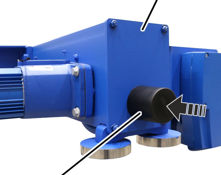
- Screw safety buffers into the buffer plates. Approx. 30 Nm.
The safety buffer must be in contact with the buffer plate and there must be no gap between them, otherwise the impact will be absorbed by the screw and not by the safety buffer.
Overview of tightening torques
Eccentric bolt
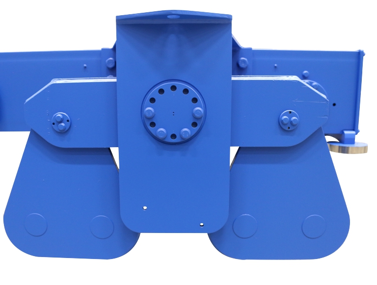
Size |
Wheel Ø |
Rib screws |
Strength category |
Tightening torque |
|---|---|---|---|---|
GM 800 |
160 |
M8x25 |
10.9 |
42 Nm |
GM 1000 |
200 |
M10x25 |
10.9 |
75 Nm |
GM 2000 |
200 |
M10x25 |
10.9 |
75 Nm |
GM 3000 |
200 |
M10x25 |
10.9 |
75 Nm |
GM 3000 |
280 |
M12x25 |
10.9 |
115 Nm |
Lift-off prevention device
Rib screw |
Tightening torque |
|---|---|
M12x30 |
115 Nm |
M16x35 |
210 Nm |
Inspection
This section applies to anyone who inspects and accepts the crane in accordance with occupational health and safety requirements
Read before starting work
Test intervals
The regular inspection is performed at least once annually.
Under certain conditions, more frequent regular inspections may be necessary. Reasons include:
- Frequent operation at the load capacity
- Working in multiple shifts
- Frequent use
- Dusty or chemically aggressive environment
The end user is responsible for checking the requirements and determining the test intervals. ABUS will gladly assist you if questions arise.
Requirements for the examiner
The end user of the crane is responsible for the proper qualifications of the examiner.
Examples of qualified persons:
- Persons with comprehensive knowledge from specialist training in engineering and in the electrical systems of cranes.
- Persons with sufficient experience in the operation, installation and maintenance of cranes.
- Persons with comprehensive knowledge regarding the relevant technical rules, directives and safety regulations applicable in the respective country.
- Persons receiving regular training from ABUS.
Scope of the test
The person qualified to inspect the wire rope hoist is responsible for the scope and type of inspection.
Overview: inspecting the wire rope hoist
In addition to the points described here, all points outlined in the other supplied product manuals must also be checked.
The decision as to whether the wire rope hoist is in a flawless condition is the sole responsibility of the examiner. Any inadequacies, if found, must be eliminated. The examiner decides whether the wire rope hoist needs to undergo inspection again afterwards.
If locally applicable regulations specify further tests, these are likewise to be carried out.
Additionally, at least the following points must be checked:
- Inspect the wire rope. See “Inspecting the wire rope”.
- Check the load hook and bottom block. See “Checking the load hook and bottom block”.
- Check the edge protection on the bottom block (visual inspection).
- Inspect the fixed point crosshead. See “Inspecting the fixed point crosshead”.
- Inspect the deflection roller crosshead. See “Inspecting the deflection roller crosshead”.
- Inspect the cable guide. See “Inspecting the cable guide”.
- Check the fixed point. See “Checking the fixed point”.
- Inspect the end clamps on the cable drum. The end clamps must be installed and must not exhibit any heavy damage.
- Check the wheel diameters. See “Checking the diameter of the wheels”.
- Check the wear on the guide rollers. See “Checking the wear on the guide rollers”.
- Check the wheel flange wear of the wheels on the wire rope hoist. See “Inspecting the wheel flange wear”.
- Check the supporting wheels. See “Checking the supporting wheels”.
- Check the lift-off prevention device. See “Checking the lift-off prevention device”.
- Check the condition of the safety buffer. See “Checking the safety buffers”.
- Check the brake on the hoist drive or travel drive.
See product manual “Pole-variable, modular ABUS hoist drive for wire rope hoists”.
- Check the braking distance of the trolley drive.
Inspecting the wire rope
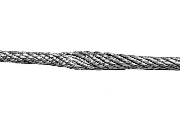
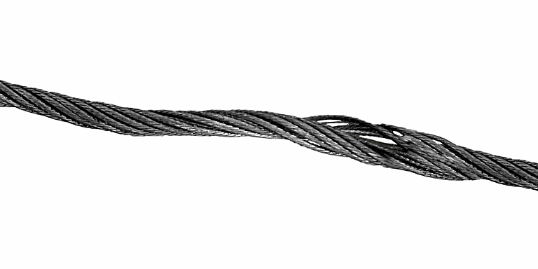
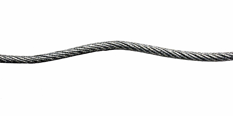
- Inspect the entire wire rope for damage. The damage shown here or any similar damage should not be detectable on the wire rope.
Examples of damage:
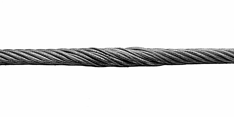
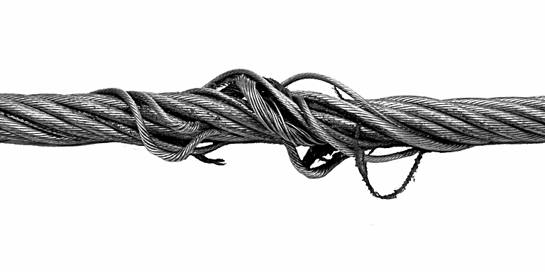
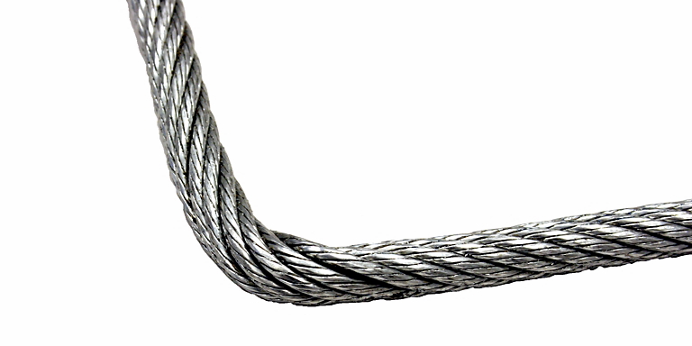
- Check the entire wire rope for broken wires. The wire rope must not exhibit more broken wires in a length of 6 times its diameter or 30 times its diameter than is specified for these lengths on the ABUS manufacturer's certificate for wire ropes in the test log book.
Examples of broken wires:
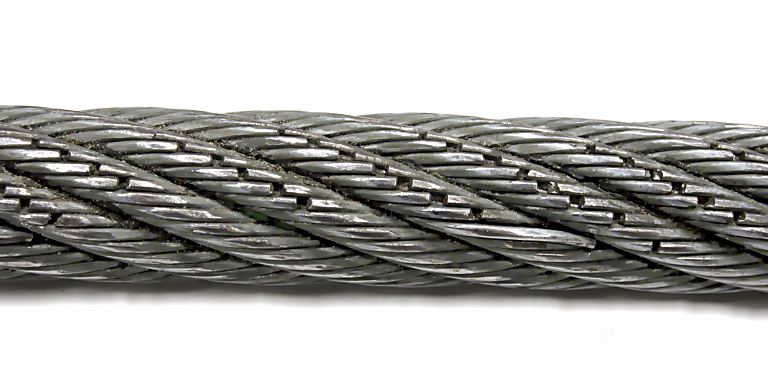
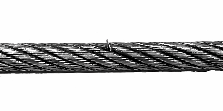
- If damage such as that pictured or similar damage is detected on the wire rope, replace the wire rope with a new one.
- If the wire rope has broken wires, but these do not exceed the permissible number, shorten the test interval until the next regular inspection.
- If the wire rope has more broken wires than permitted, replace the wire rope with a new one.
Checking the load hook and bottom block
Checking for ease of movement
Load hook crosshead
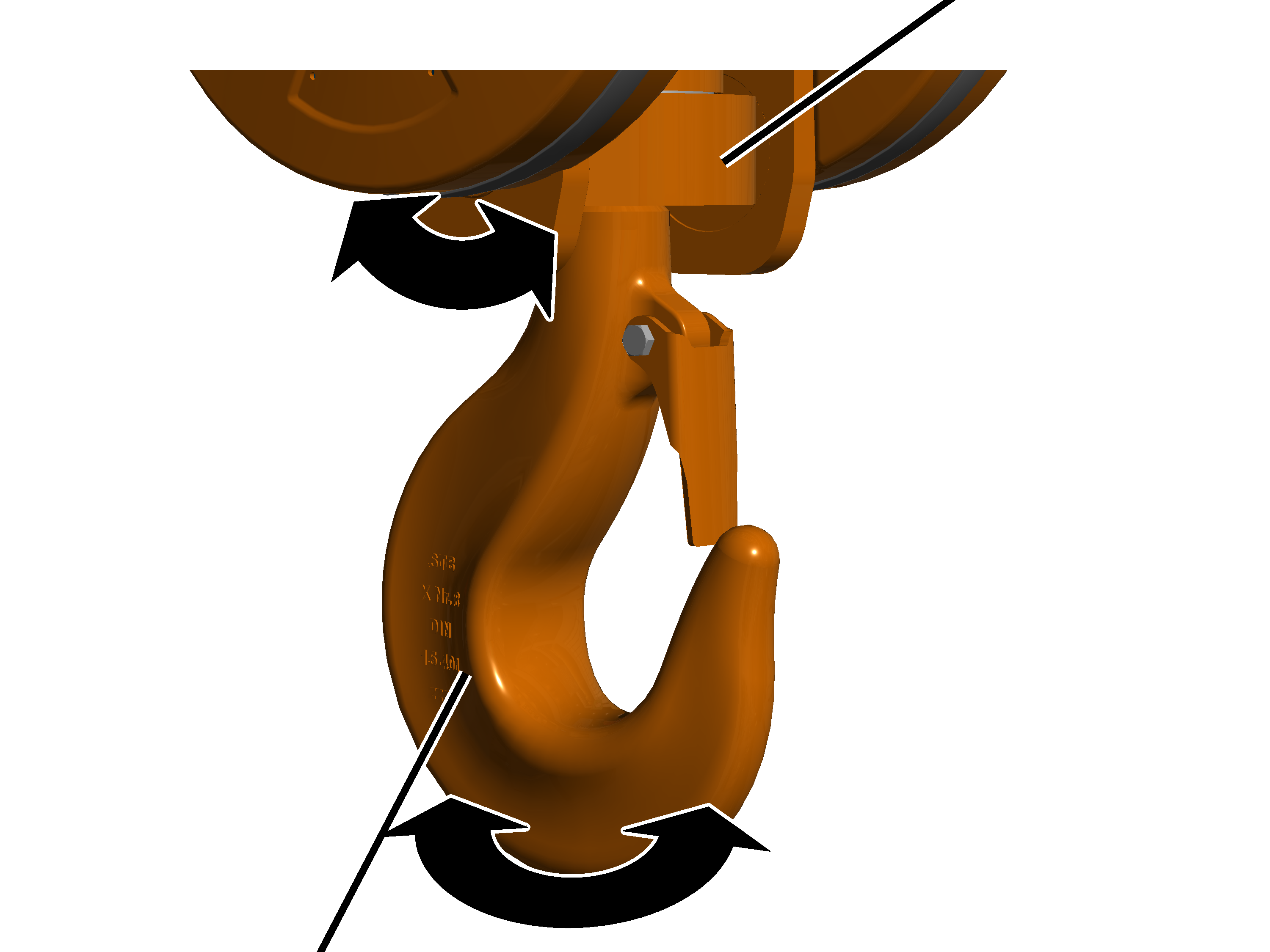
- Rotate the load hook to the left and right.
The load hook must be easy to move and freely rotatable.
- Slew the load hook backwards and forwards at the load hook crosshead.
The load hook crosshead must be freely slewable.
- If the load hook is not easy to move or freely rotatable or slewable, it must be repaired.
Inspecting the brackets on the bottom block
Bracket
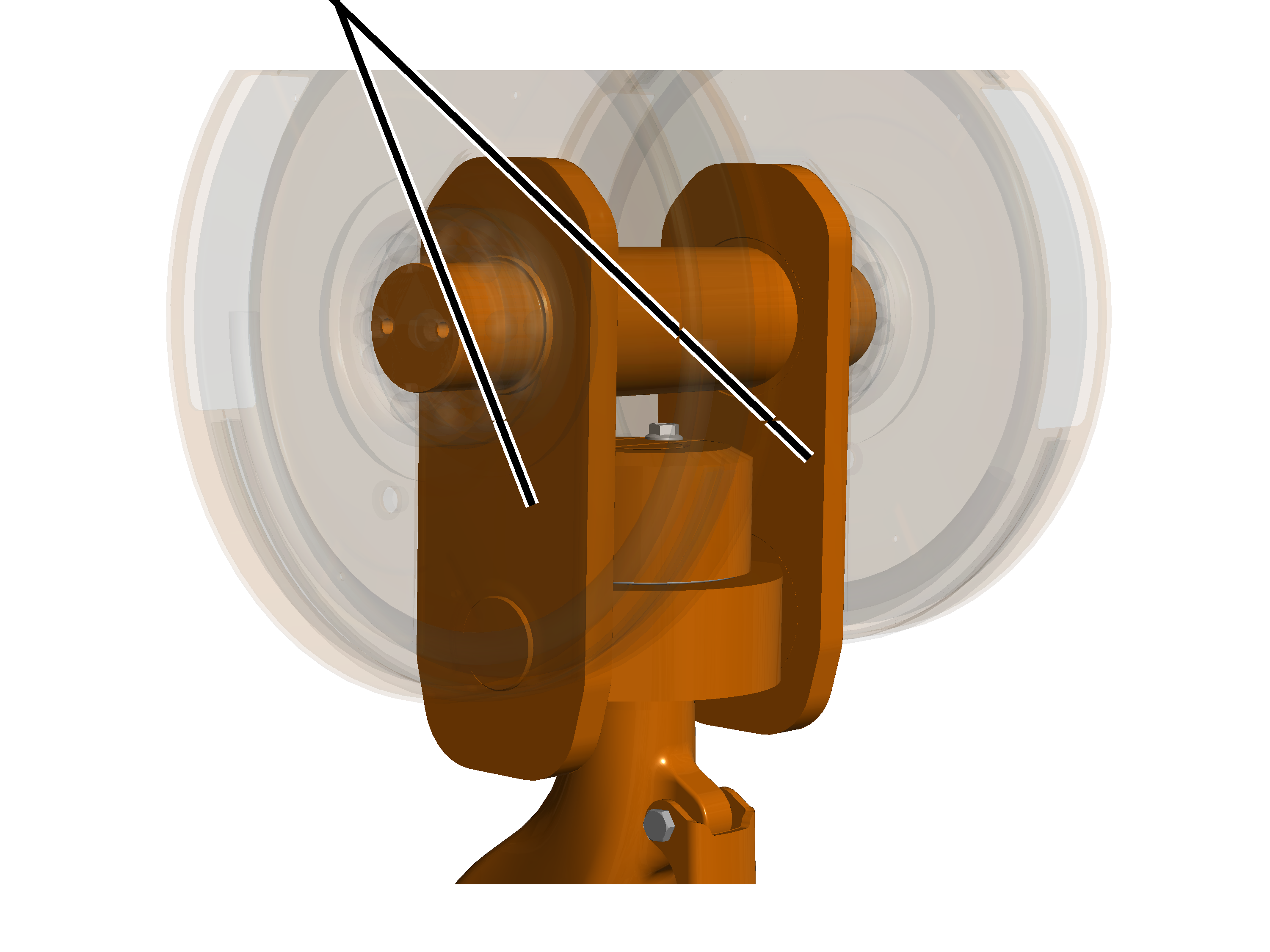
- Inspect the brackets. They must not exhibit any cracking, deformation or other signs of damage.
- If the brackets are deformed or damaged in any other way, they must be replaced.
Measuring deformation and wear of the load hook
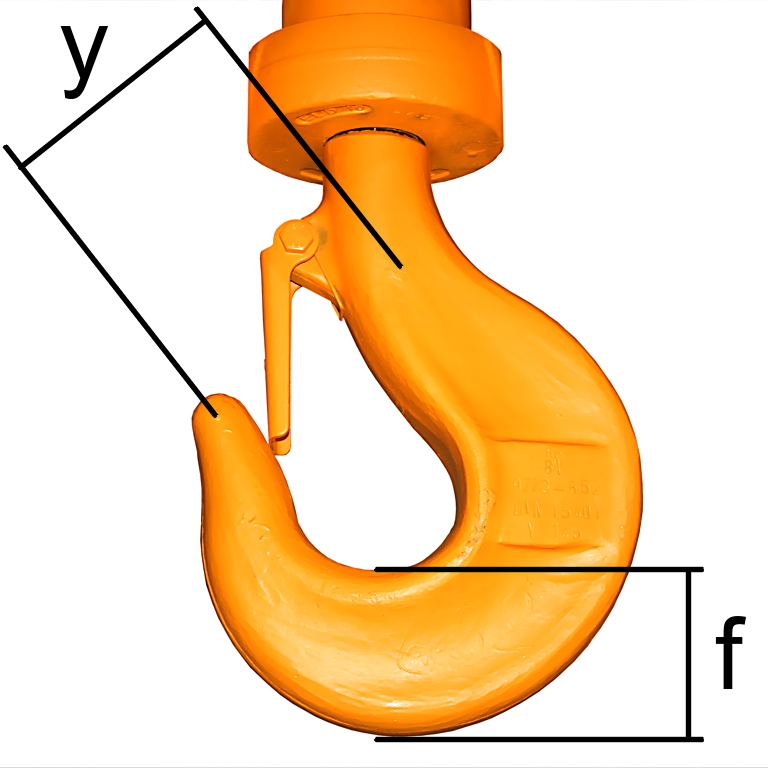
- Measure the distance ‘y’ between the two stamped markings on the load hook.
- Read the reference distance for ‘y’ from the test log book or, if applicable, from the load hook itself.
The measured distance ‘y’ must not be greater than 1.1 times the reference distance ‘y’.
With ramshorn hooks, the distances ‘y1’ and ‘y2’ from the respective engraved marking on the tip of the load hook to the marking on the hook shank must each be measured and compared separately.
- Measure the base height ‘f’ of the load hook.
- Compare the measured value with the table.
The measured base height ‘f’ must not be smaller than given in the table. The table specifies the minimum base height.
Size of load hook |
Type of load hook |
Minimum base height, ‘f’ [mm] |
|---|---|---|
1 |
Normal hook |
38 |
1.6 |
Normal hook |
45.6 |
2.5 |
Ramshorn hook |
47.5 |
2.5 |
Normal hook |
55.1 |
4 |
Ramshorn hook |
57 |
4 |
Normal hook |
63.7 |
6 |
Ramshorn hook |
71.3 |
6 |
Normal hook |
80.8 |
Size of load hook |
Type of load hook |
Minimum base height, ‘f’ [mm] |
|---|---|---|
8 |
Ramshorn hook |
80.8 |
8 |
Normal hook |
90.3 |
10 |
Ramshorn hook |
90.3 |
10 |
Normal hook |
100.7 |
12 |
Ramshorn hook |
100.7 |
12 |
Normal hook |
112.1 |
- If the load hook has been widened to a greater degree than is allowed or if the base height is below the permissible limit, replace the load hook.
Do not carry out any repair welding (e.g. build-up welding) on the load hook or on the load hook nut.
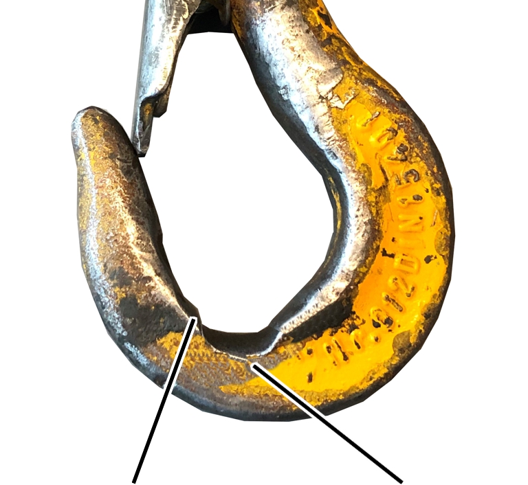
- Check the wear surfaces in the hook bed. They must merge gradually with the surrounding surfaces. They must not have any sharp score marks and edges or other surface faults.
- Inspect the edges. The side edges on the load hook should not have any exterior protruding burrs or similar surface faults.
- If the wear surfaces or side edges do have sharp score marks or edges, these may be smoothed (e.g. filed). The limit values for base height given above must be observed even after smoothing.
Inspecting the load hook surface
- Inspect the load hook surface. It must not have any faults, cracks or corrosion.
- If the surface of the load hook is to any extent not OK, disassemble the load hook and inspect the surface of the hook shank. It must not have any faults, cracks or corrosion.
Inspecting the anti-rotation device of the load hook nut
For load hooks with anti-rotation device in the form of a slotted spring pin:
Load hook nut
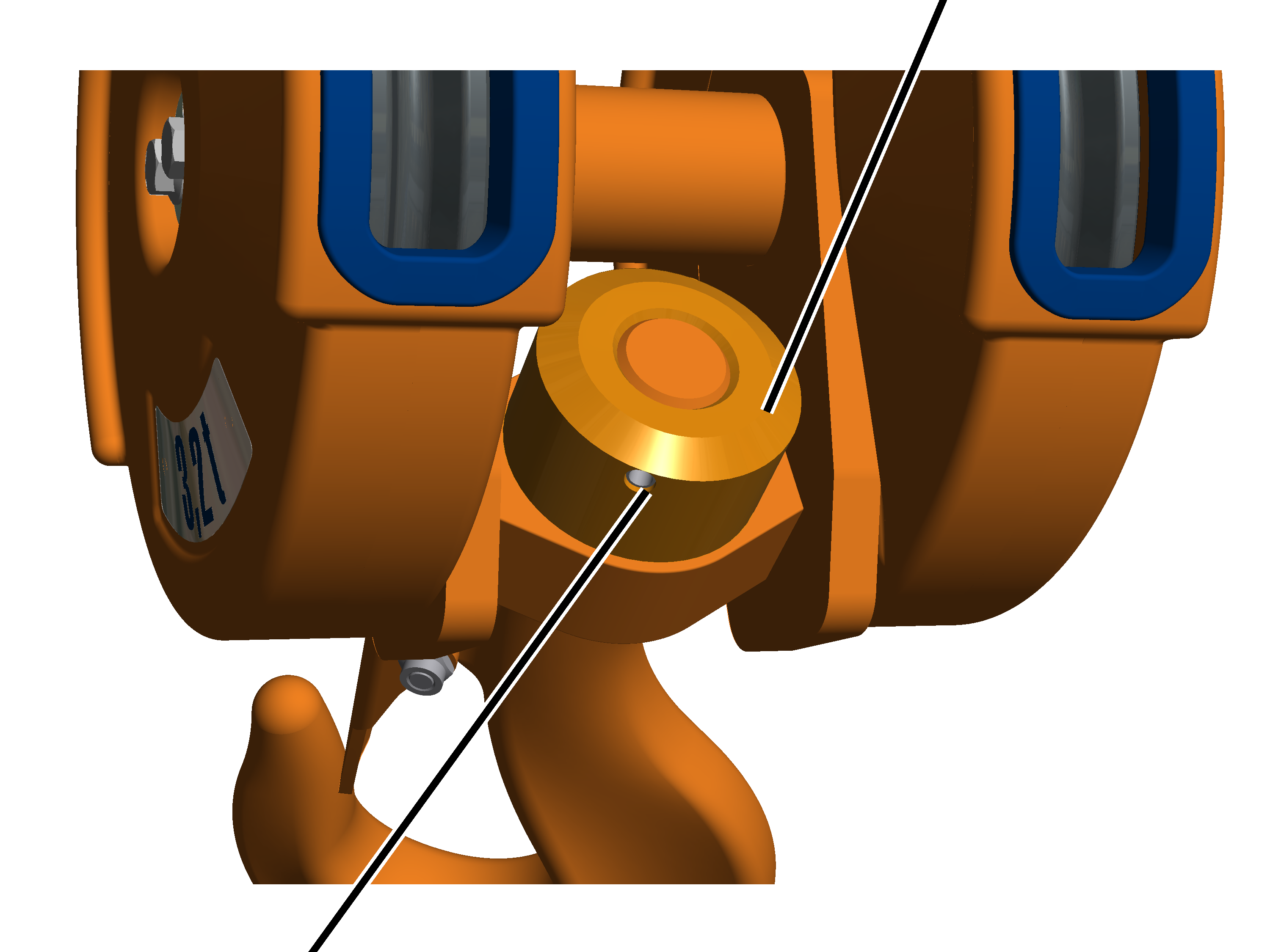
- Tilt the load hook until the anti-rotation device is clearly visible.
- Inspect the anti-rotation device. The slotted spring pin must be present, may not be damaged or broken and it must sit securely.
- If the slotted spring pin is missing or damaged, it must be replaced.
For load hooks with anti-rotation device by means of safety plate:
Locking plate
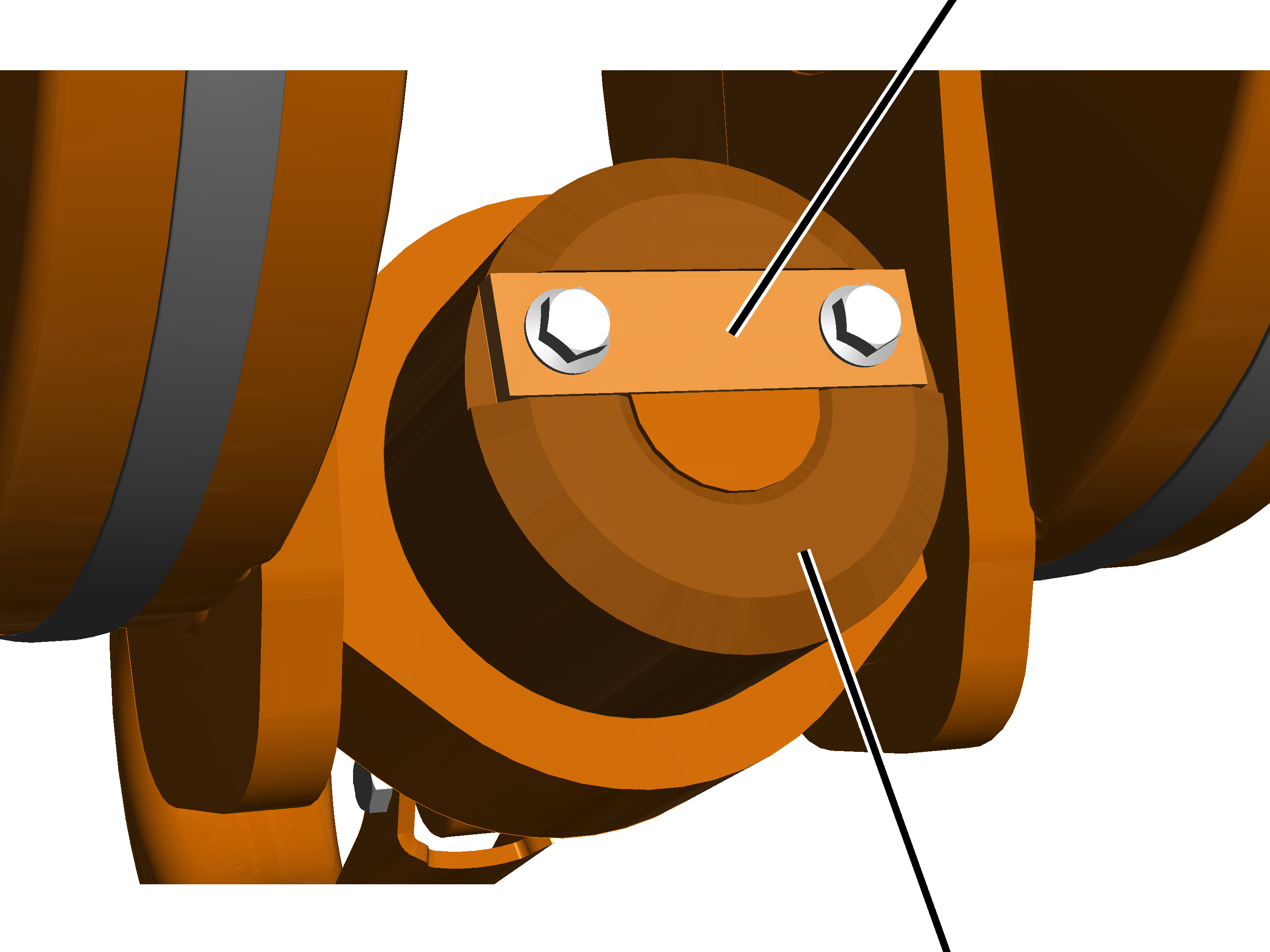
- Tilt the load hook until the anti-rotation device is clearly visible.
- Inspect the anti-rotation device. The safety plate must be present, undamaged and sit securely.
- If the safety plate is missing or damaged, it must be replaced.
Inspecting the hook safety latch
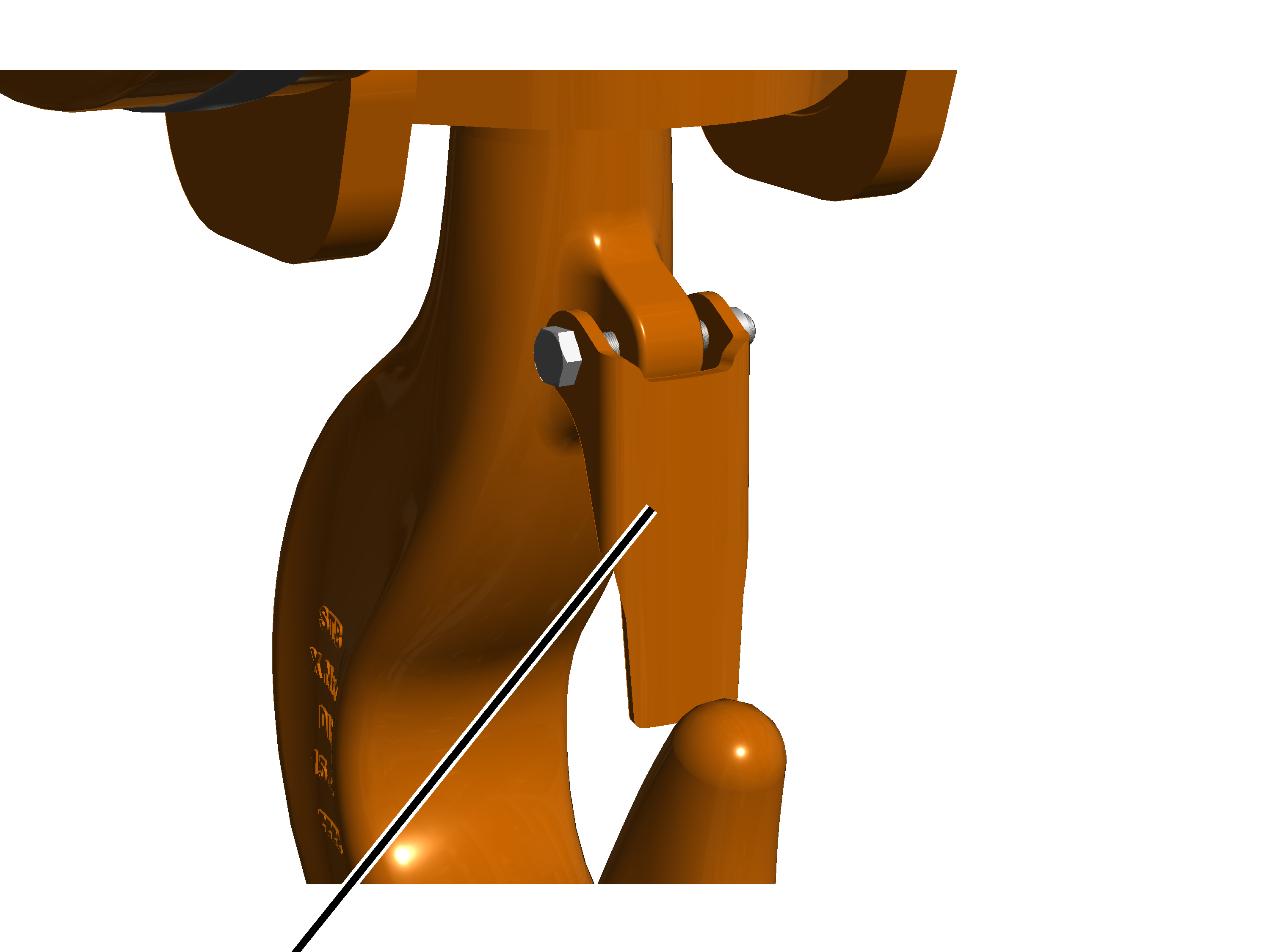
- Inspect the hook safety latch. It must be present, functional and easy to move, and must not be deformed or damaged in any other way.
- If the hook safety latch is missing, damaged or not working properly, it must be replaced.
Inspecting the fixed point crosshead
Bolt with
SL safety clipBolt with
SL safety clip
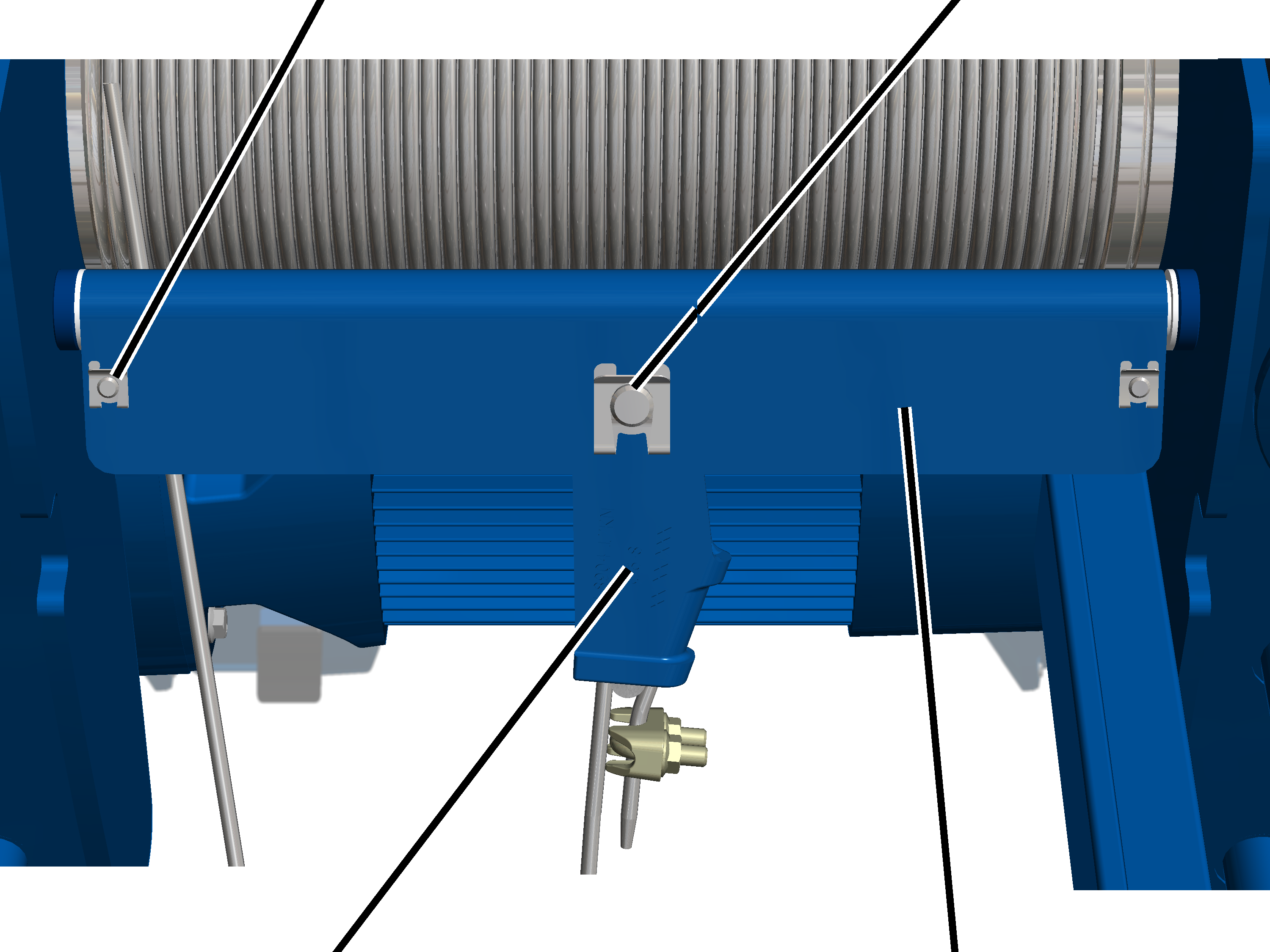
- Inspect the fastening. The fixed point crosshead must be securely fastened and all bolts must be secured with SL safety clips.
- Inspect the fixed point crosshead.
The drilled holes and the lower opening must not exhibit any cracking or other damage.
- Check bearing bushes for damage. The bearing bushes must not exhibit any cracking or other damage.
- If components are missing or damaged: replace the components.
See “Exchanging the fixed point crosshead with rope socket and rope wedge”.
Inspecting the deflection roller crosshead
Only with reeving 4/1
Bolt with
SL safety clipBearing bush
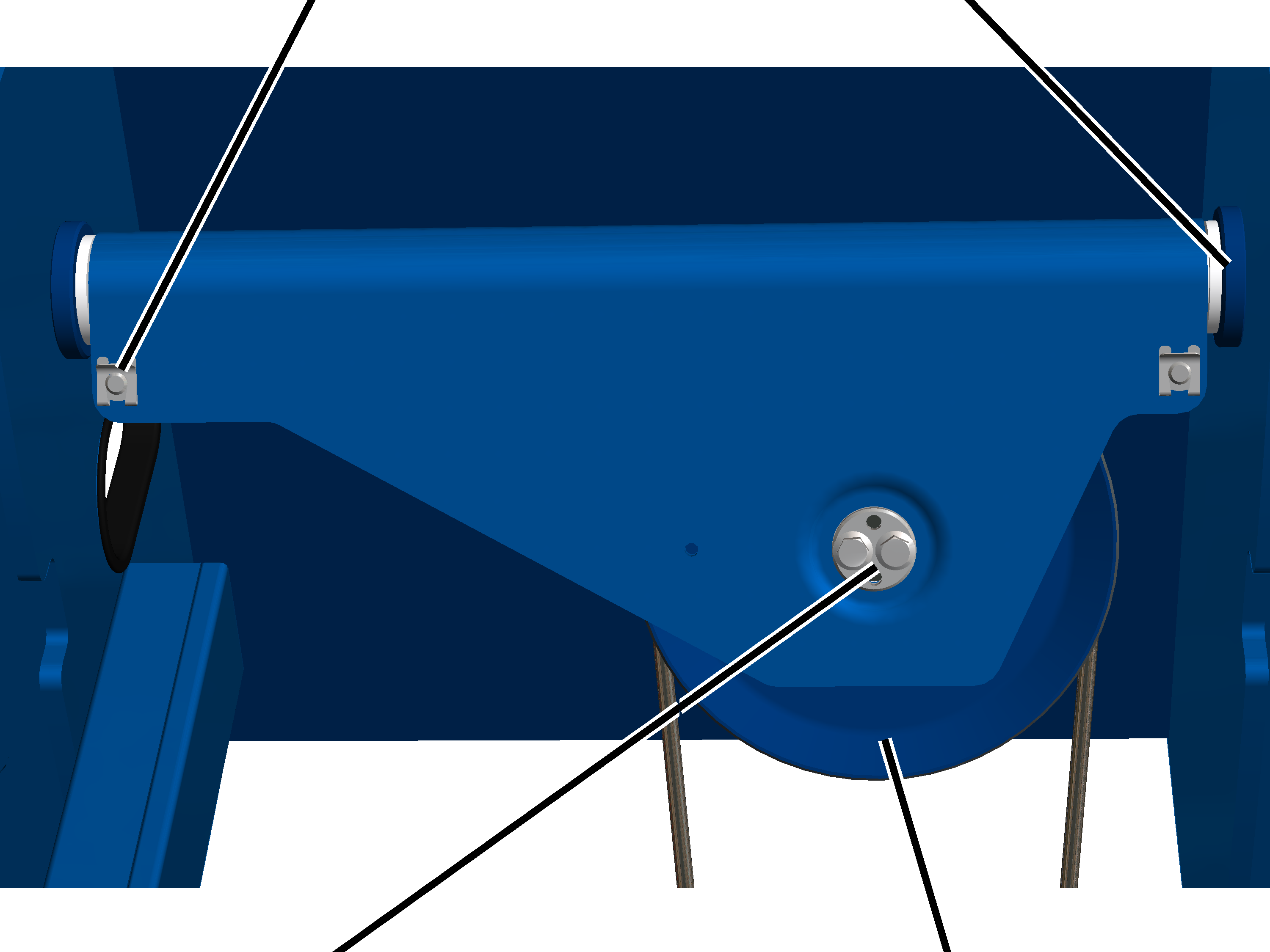
- Inspect the deflection roller crosshead.
The drilled holes must not exhibit any cracking or other damage. - Inspect the deflection roller.
It must not exhibit any deep grooves or heavy wear.
If necessary, the deflection roller can be carefully inspected using a special template. Please contact ABUS Service for this. See “ABUS Service”.
- Bolts and SL safety clips must be in place and secured.
- Check bearing bushes for damage. The bearing bushes must not exhibit any cracking or other damage.
- If components are missing or damaged: replace the components.
Inspecting the cable guide
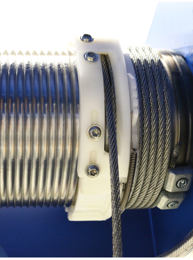
- Inspect the cable guide. The plastic parts must not be cracked, deformed or have abraded areas caused by the wire rope.
- Check the cable guide for ease of movement.
- Check the lubrication of the cable guide.
- If the cable guide is damaged: replace the cable guide. See “Replacing the wire rope”.
Checking the fixed point
Checking the rope wedge
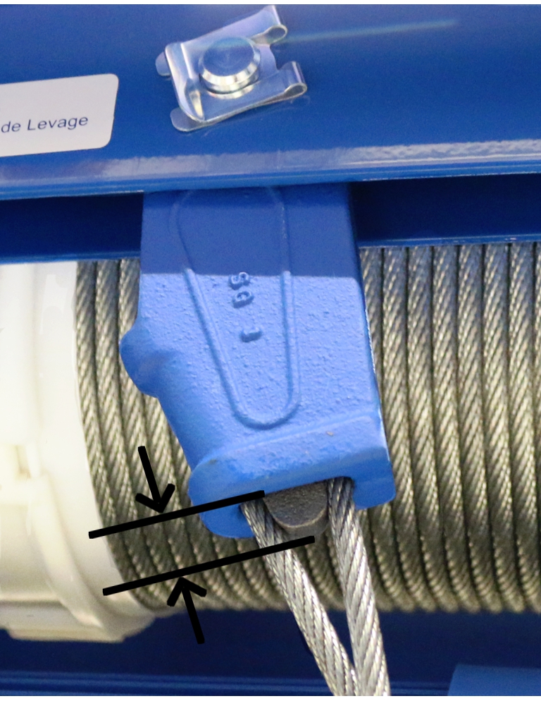
- Measure the rope wedge protrusion (lower edge of rope wedge to lower edge of rope socket).
- Measure the rope clamp spacing (upper edge of dead end rope grip to lower edge of rope wedge).
- The measured values may not be higher than the values in the table.
Size |
Maximum rope wedge protrusion |
Minimum rope wedge protrusion |
|---|---|---|
GM 800 |
19 mm |
18 mm |
GM 1000 |
4 mm |
3 mm |
GM 2000 |
2 mm |
0 mm |
GM 3000 |
18 mm |
16 mm |
- If the rope wedge protrudes too far out of the rope socket, or if the dead end rope grip is too close to the rope wedge: replace rope socket and rope wedge. See “Replacing the wire rope”.
Note
The minimum rope clamp spacing specified is always exactly equal to the wire rope diameter of the wire rope hoist.
Checking the diameter of the wheels
The running surfaces of the wheels become worn during operation. This reduces the diameter of the wheels.
Exposing the wheel
Buffer plate
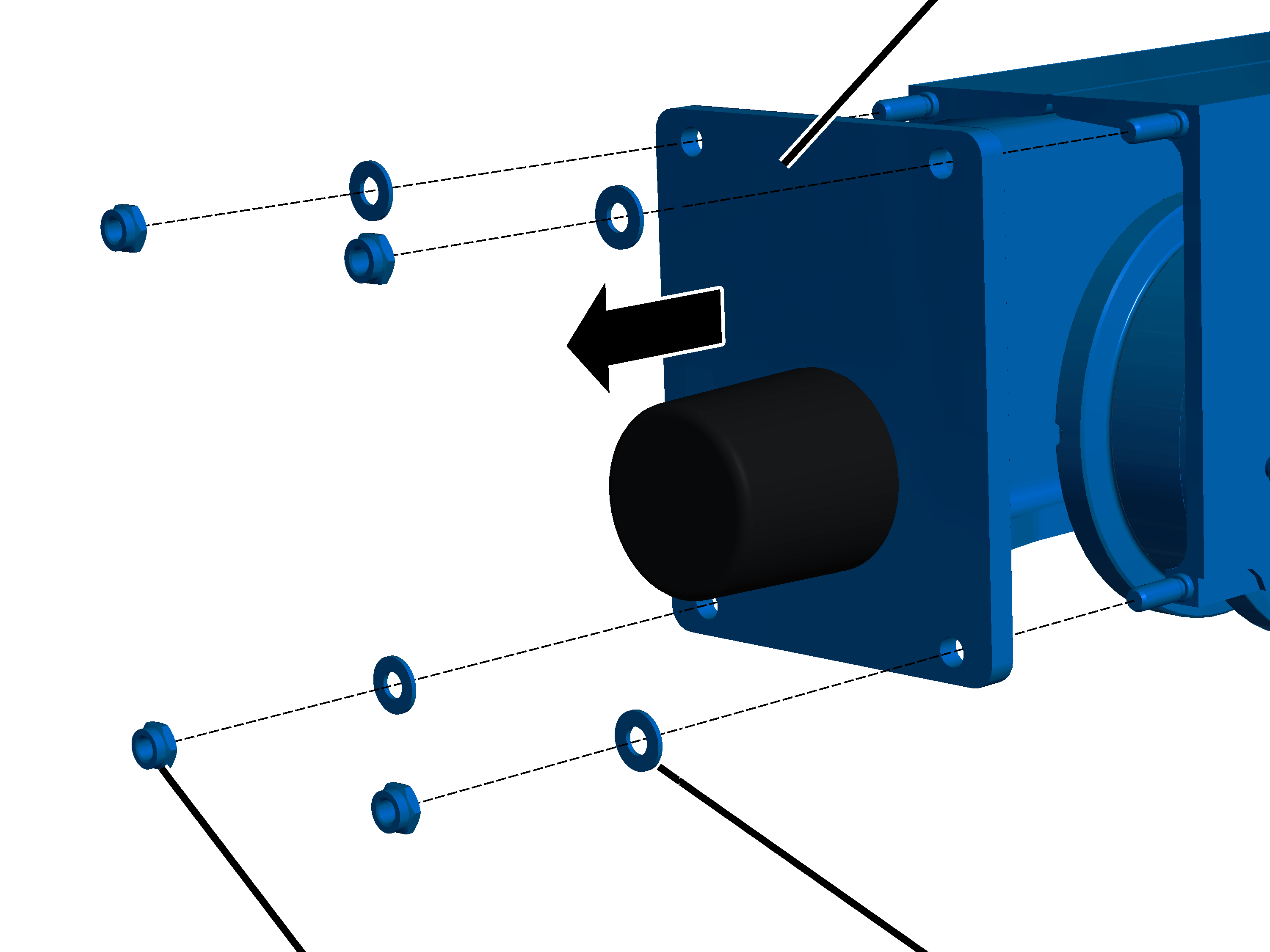
- Unscrew the self-locking nuts (4x).
- From size 160: remove the plastic washers (4x).
- Remove the buffer plate.
Measuring the diameter
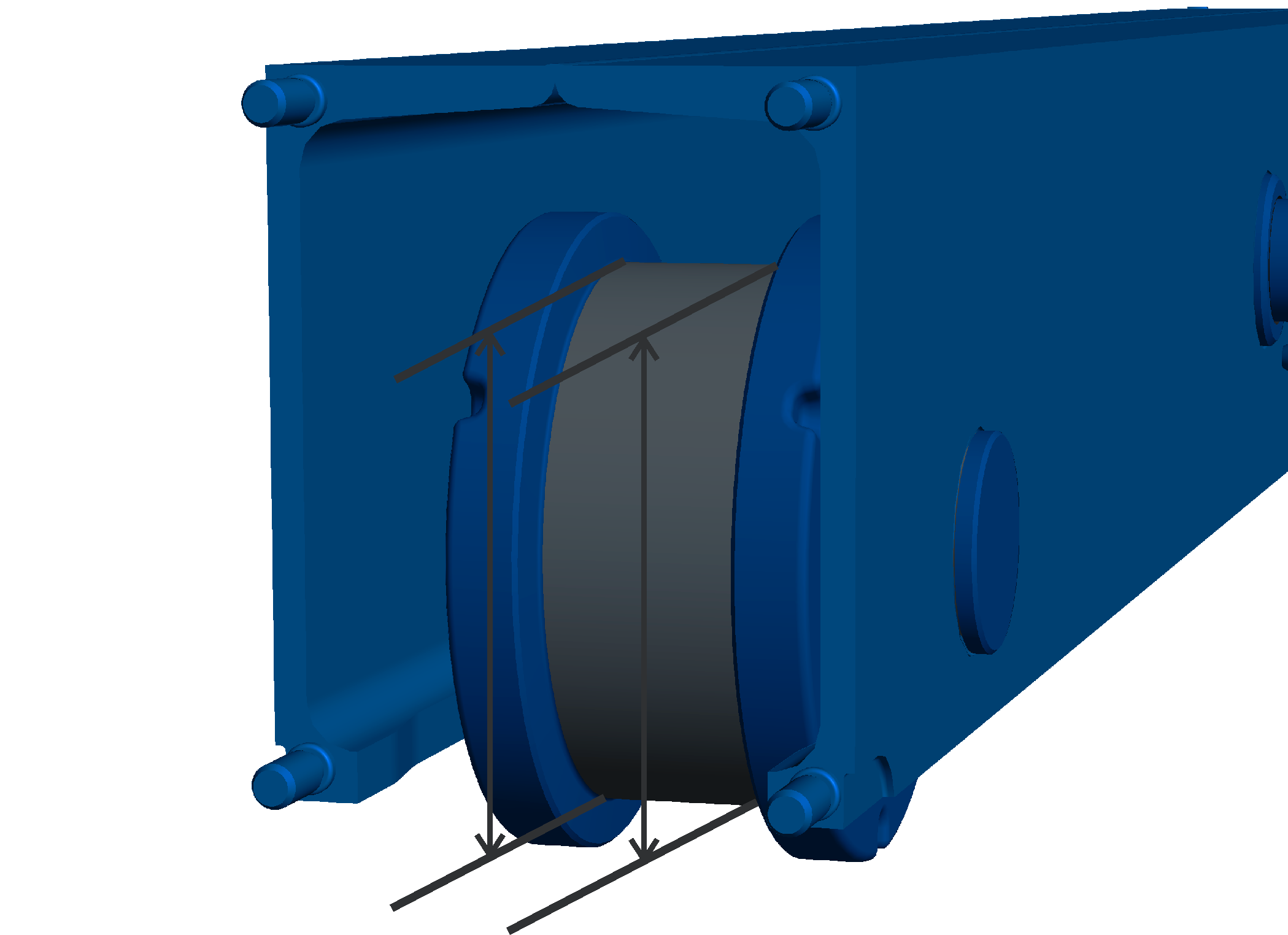
- Measure the diameter of the wheel at multiple points over the width of the wheel.
- The diameter may not be smaller than is specified in the table.
If the diameter is smaller, the wheel must be replaced. See “Disassembling the powered wheel”.
Wheel |
Maximum permissible wear |
Minimum diameter |
|---|---|---|
160 |
-3 mm |
157 mm |
200 |
-4 mm |
196 mm |
280 |
-5 mm |
275 mm |
Checking the wear on the guide rollers
The wear on the guide rollers is checked based on the clearance between the guide rollers and the trolley track.
Checking the wear
Guide roller
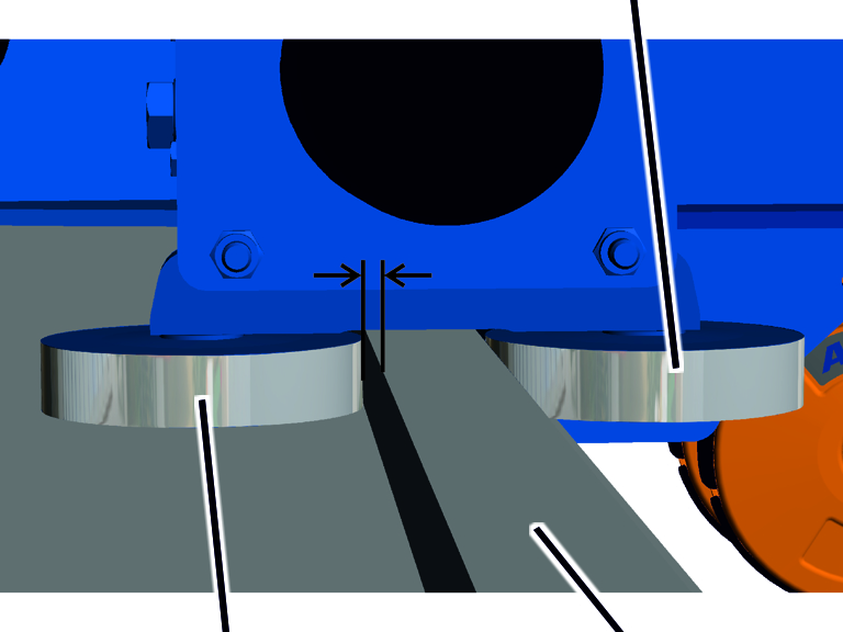
- Measure the distance between guide roller and trolley track on both sides.
- The distance (between guide roller and trolley track) may not be larger than 5 mm on both sides.
If the distance is greater than this, the guide rollers must be replaced.
Determining the diameter for new guide rollers
If the distance between guide roller and trolley track is too large (see previous section), the guide rollers must be replaced.
During operation of the wire rope hoist however, both the guide rollers AND the trolley track are subjected to wear. Since only the guide rollers can be replaced, they may need to be exchanged for larger ones than were previously used in order to compensate for the wear on the trolley track.
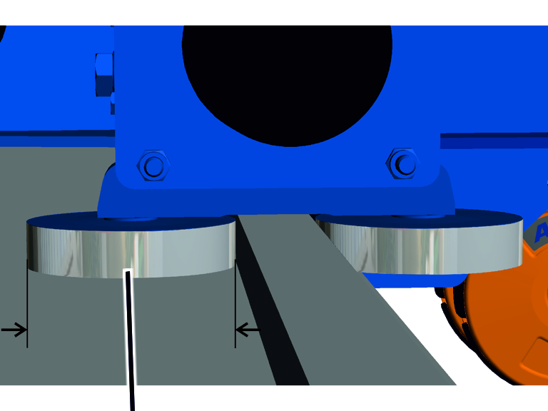
- If possible: Measure the diameter of the guide roller above the trolley track.
This area of the guide roller frequently has no contact with the trolley track and can therefore be used to determine the original diameter.
- Determine the diameter of the new guide roller:
- The distance between the guide rollers and the trolley track should be as close as possible to 5 mm. This applies to the entire length of the trolley track.
- The distance between the guide rollers and the trolley track may not be less than 5 mm. This applies to the entire length of the trolley track.
Inspecting the wheel flange wear
The undercuts in the wheel flanges are a sign of wear on the wheel flange.
Note
First check the clearance between wheel flange and rail. The wheel flanges may not exhibit any wear, since the wire rope hoist is delivered with guide rollers.
If the clearance between wheel flange and rail is too large, the wheel flanges must be inspected.
Wheel flange
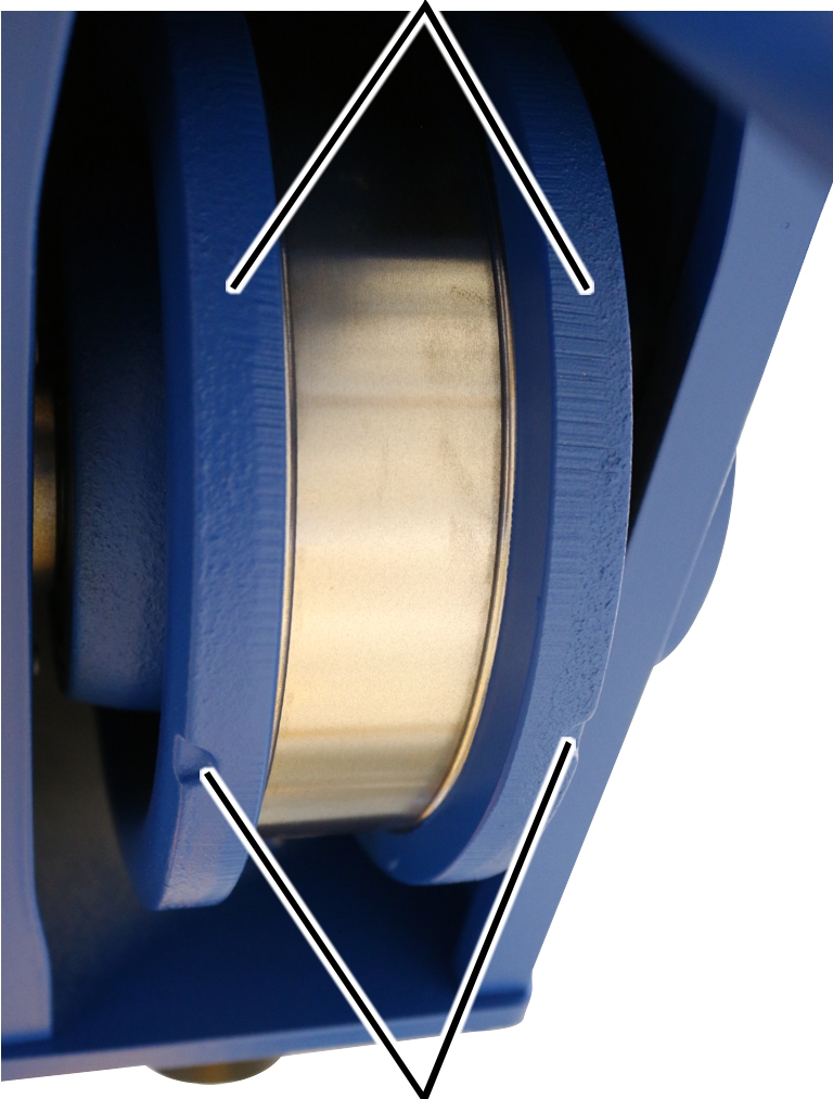
- Inspect the wheel flanges of the wheels: The wheel flanges must not be worn so much that a continuous crack can be seen in the wheel flange (rather than undercuts). If they are, replace the wheels. See “Disassembling the powered wheel”.
Checking the supporting wheels
On the wire rope hoist, supporting wheels run under the upper flange.
The running surfaces of the supporting wheels become worn during operation. This reduces the diameter of the supporting wheels.
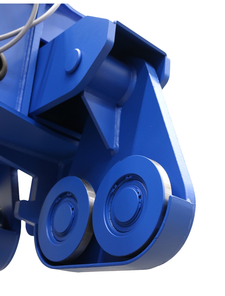
- Measure the diameter of the supporting wheels at multiple points over the width of the wheel.
- The diameter may not be smaller than is specified in the table.
If the diameter is smaller, the supporting wheels must be replaced. See “Replacing the supporting wheels”.
Supporting wheel |
Maximum permissible wear |
Minimum diameter |
|---|---|---|
130 |
-3 mm |
127 |
160 |
-3 mm |
157 |
Checking the lift-off prevention device
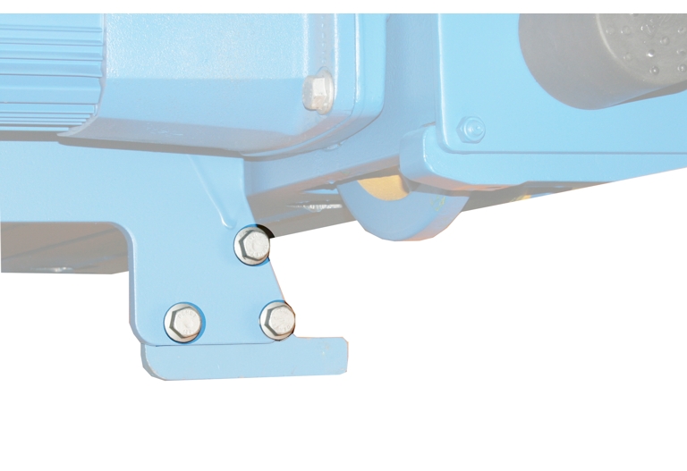
- Check the lift-off prevention device for wear and damage.
If the lift-off prevention device is damaged, it must be replaced.
- Test the firm seating of the lift-off prevention device with a light hammer tap.
If the rib screws on the lift-off prevention device are loose, these must be tightened. See “Installing the lift-off prevention device”.
Checking the safety buffers
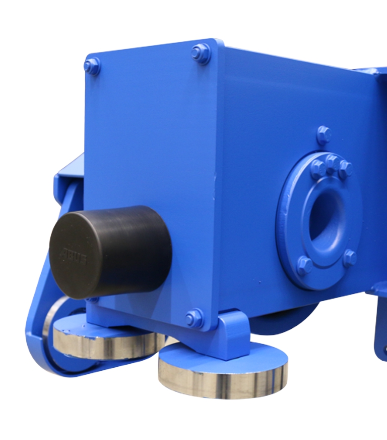
- Check all the safety buffers. The safety buffers must not be porous, pinched, bent or otherwise damaged.
- Check the material of the safety buffers all the way round. The plastic must not be cracked anywhere on the surface.
- Press the safety buffers with your finger. The safety buffers must be able to be pressed in slightly and be deformable.
- If one of the safety buffers is damaged in any way, replace all the safety buffers on the wire rope hoist. See “Replacing the safety buffer”.
- If one of the safety buffers cannot be pressed in, replace all the safety buffers on the wire rope hoist. See “Replacing the safety buffer”.
Maintenance
This section applies to anyone who maintains, repairs or modifies the crane.
The end user of the crane is responsible for the selection and proper qualifications of the maintenance personnel.
Examples of qualified persons:
- Persons with comprehensive knowledge from specialist training in engineering and in the electrical systems of cranes.
- Persons with sufficient experience in the operation, installation and maintenance of cranes.
- Persons with comprehensive knowledge regarding the relevant technical rules, directives and safety regulations applicable in the respective country.
- Persons receiving regular training from ABUS.
ABUS assumes no liability for damage due to incorrectly performed maintenance work done by unqualified personnel.
ABUS recommends having the maintenance work performed by ABUS Service.
Use only original ABUS replacement parts. Otherwise, all warranty claims will be rendered invalid.
Instructions regarding safety when performing maintenance work
Observe the following safety instructions during all maintenance work on the wire rope hoist.
- Switch off the mains switch. Secure the switch to ensure it cannot be turned back on accidentally.
- Open the fuse isolating link in the crane panel. Secure the fuse isolating link with a padlock so that it cannot be accidentally closed again.
- Use suitable lifting platforms and fall protection equipment.
- Adequately cordon off the operating range around the lifting platform.
- Switch off other cranes on the same crane track or cranes that are above or below the crane to be serviced. Secure the switches to ensure they cannot be turned back on accidentally. Other cranes could otherwise overturn the lifting platform or hit the crane to be serviced.
- Notify personnel in the area that maintenance work will be performed.
- Only trained electricians should work on the crane electrical system!
- Even after the emergency stop button has been pressed, life-threatening high voltages are still present in the crane control and in the trolley control.
These safety instructions apply specifically to the wire rope hoist:
- Danger of crushing!
Fingers could be crushed on the wheels, cable drum and deflection roller should the wire rope hoist make unforeseen movements, or if work is performed without sufficient attention.
Secure the wire rope hoist. Work with caution!
Replacing the wire rope
If the wire rope is damaged or has more broken wires than permitted (see “Inspecting the wire rope”), it must be replaced.
If the cable guide is damaged (see “Inspecting the cable guide”), it must be replaced.
The wire rope and cable guides are wearing parts that are subject to heavy loads. They subject each other to wear during operation. This is why the wire rope and cable guide should always be replaced together.
The wire rope is a special lifting rope with a very high breaking strength. This ensures that it has a longer service life than a normal wire rope. This is why only genuine wire ropes from ABUS may be used.
If the rope wedge or the rope socket are damaged (see “Exchanging the fixed point crosshead with rope socket and rope wedge”), they need to be replaced. They are usually replaced when the wire rope and cable guide are replaced.
These safety instructions apply specifically to changing the wire rope:
- Cordon off a generous space for the work area under the wire rope hoist.
- Ensure that the floor is swept clean.
This reduces soiling of the new wire rope.
- Scissors lift platform with adequate surface area for setting down the bottom block.
Observe the load capacity of the lift platform!
- If an unrolling device is available to unroll the wire rope, sufficient free space for this is required.
- Position a scrap container or similar receptacle in the immediate vicinity of the lift platform and bottom block for the old wire rope.
- For a wire rope diameter larger than 11 mm, the rope change should be performed with the assistance of a second person.
Preparing for wire rope replacement
- Move the load hook under the upper limit switch range.
- Measure, and note the position of the load hook.
This makes adjusting the hoist limit switch after replacing the wire rope in many cases unnecessary.
Only with ABUControl
If ABUControl is installed for the wire rope hoist, refer to the product manual “ABUControl”, section “Exchanging the wire rope” to prepare for the rope change.
Further steps for the wire rope change are then described in this product manual.
Only for ABUS electrics 3 with contactor control or ABULiner
Disassembling the hoist limit switch
In order for the wire rope to be unwound from the cable drum using a motor, the hoist limit switch must be removed. Otherwise the cable drum will stop at the lowest hook position.
Hoist limit switchPins on the cable drum
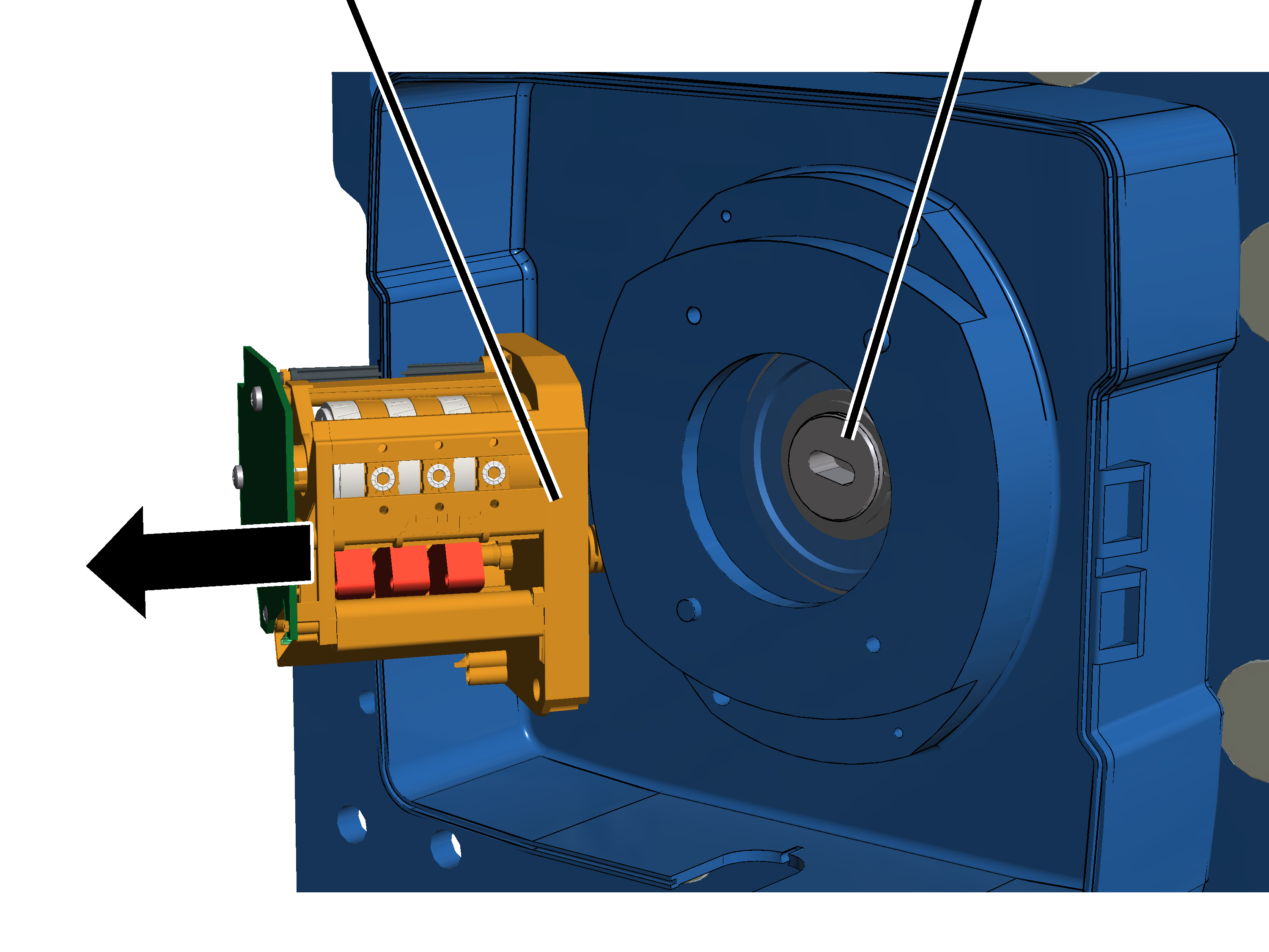
- Open the hoist limit switch housing.
- Unscrew and remove screws (2x).
- Pull off the hoist limit switch.
- Leave the shaft of the hoist limit switch in the same position, and do not turn it.
This makes adjusting the hoist limit switch after replacing the wire rope in many cases unnecessary.
- Secure the hoist limit switch to ensure it does not fall down or hang from the connection cables.
Disassembling the fixed point
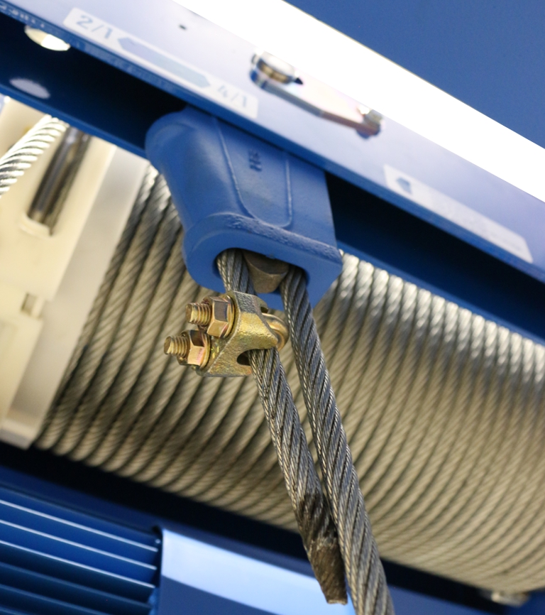
Dead end rope grip
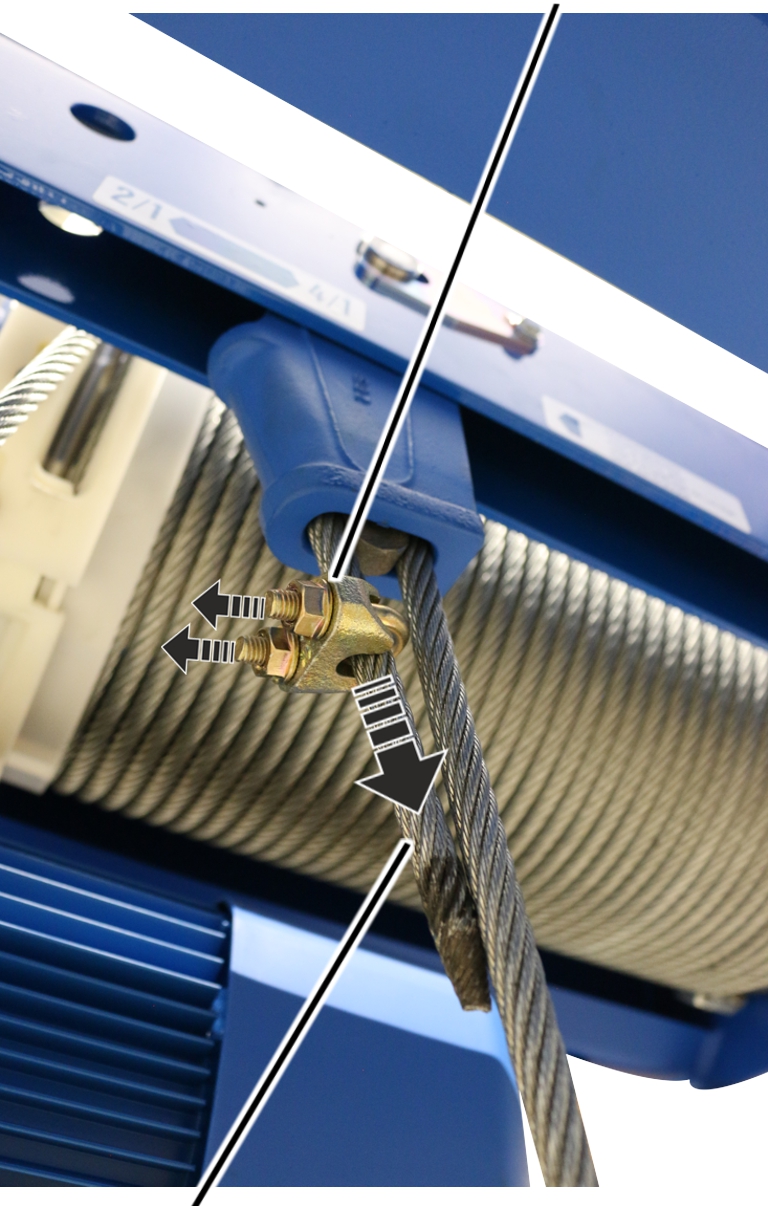
- Release the dead end rope grip.
- Pull the dead end rope grip from the end of the wire rope.
Only with exchange of rope socket with rope wedge
If the rope socket or the rope wedge are damaged, they must be replaced.
Disassembling the rope socket
Measurement boltRib screw
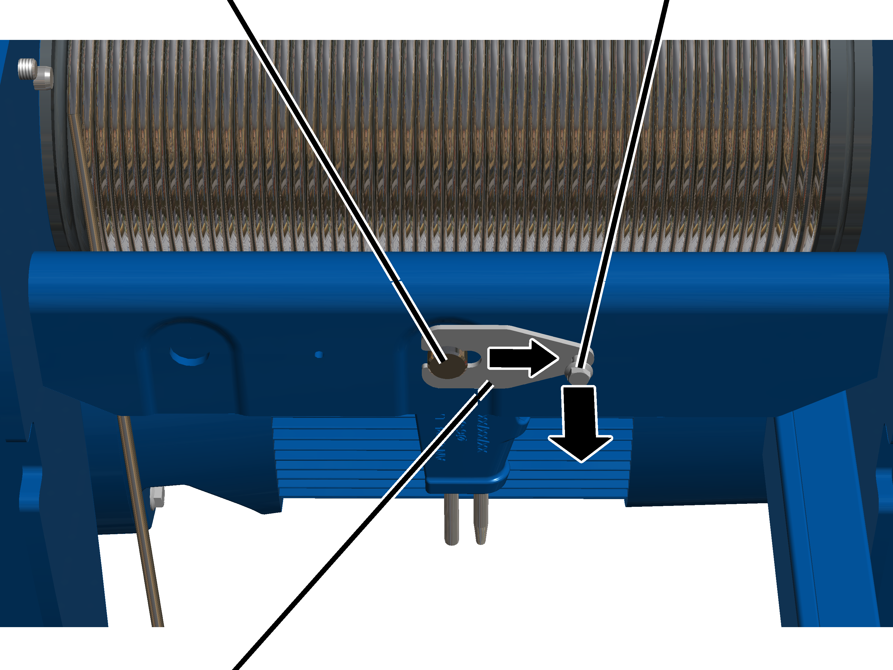
- Release rib screw M6x12.
- Slide the mount from the measurement bolt.
Measurement boltRib screw
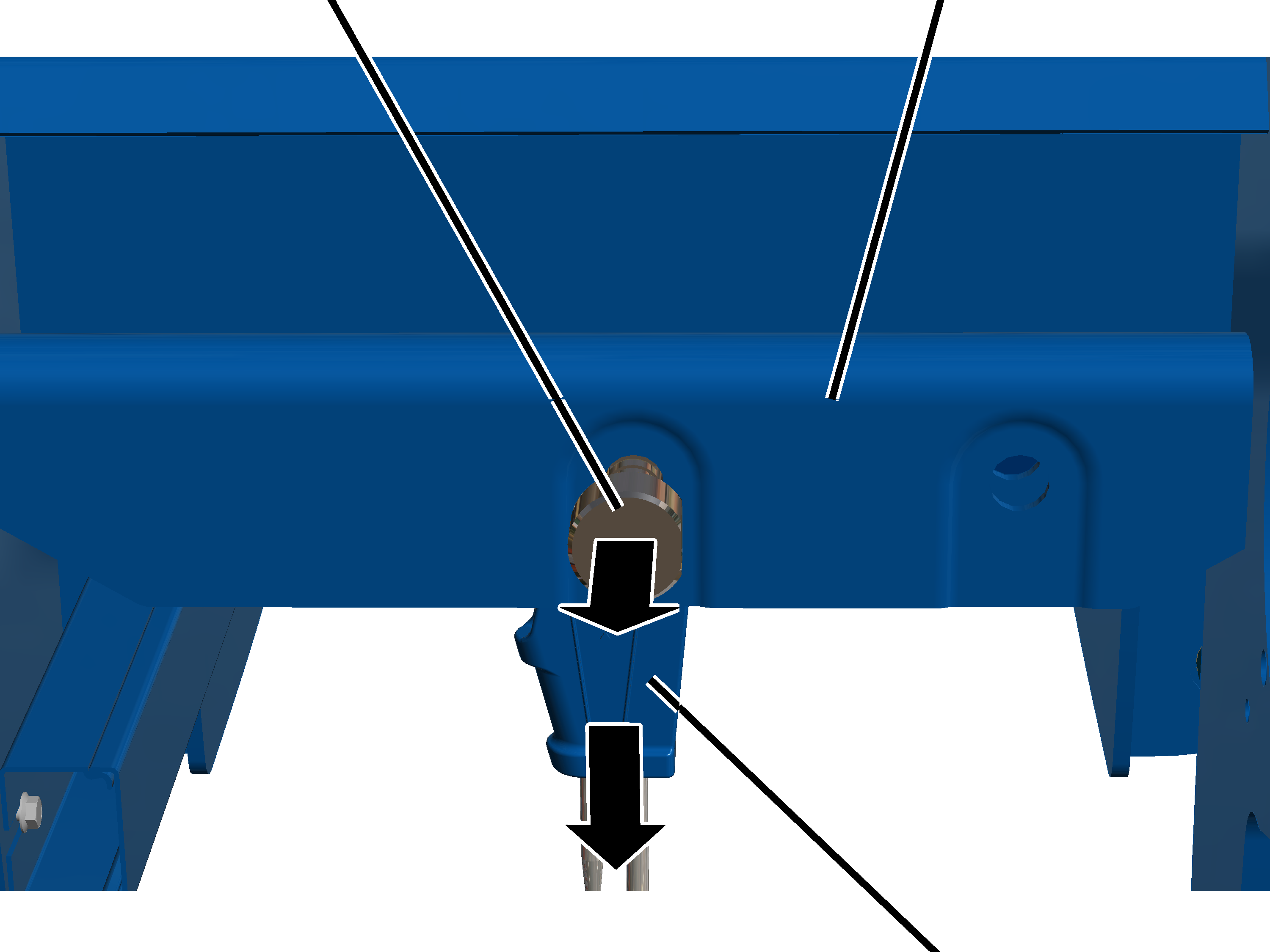
- Pull the measurement bolt out of the fixed point crosshead and the rope socket.
- Pull the rope socket out of the fixed point crosshead.
Rope socket
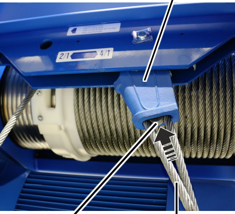
- Drive the rope wedge out of the rope socket and take it out.
If the rope wedge is stuck:
- Disassemble the rope socket.
- Turn the rope socket over and knock out the rope wedge from above.
The rope wedge can in this way be more easily knocked out of the rope socket.
Fixed point crossheadRope socket
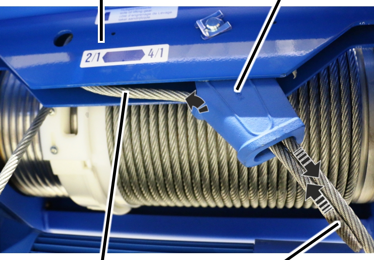
- Push the end of the wire rope out of the rope socket.
Fixed point crossheadRope socket
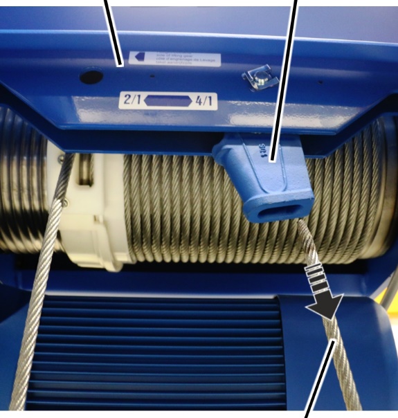
- Pull the wire rope out of the rope socket.
Pulling the wire rope out of the bottom block
The rope guard in the bottom block will be damaged if the wire rope is pulled along the rope guard quickly to remove it from the bottom block. If the rope guard is to be used again, it should be disassembled beforehand.
ABUS recommends replacing the rope guard together with the wire rope.
On all openings on the bottom block:
ScrewdriverBottom block cover
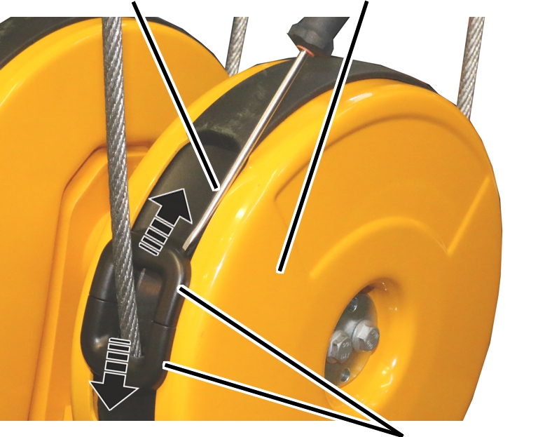
- Insert the screwdriver laterally between the rope guard and bottom block cover as shown in the figure.
- Use the screwdriver to unhook the load hooks on the left and right of the rope guard at the same time.
- Pull the rope guard (2x) apart and remove it from the bottom block.
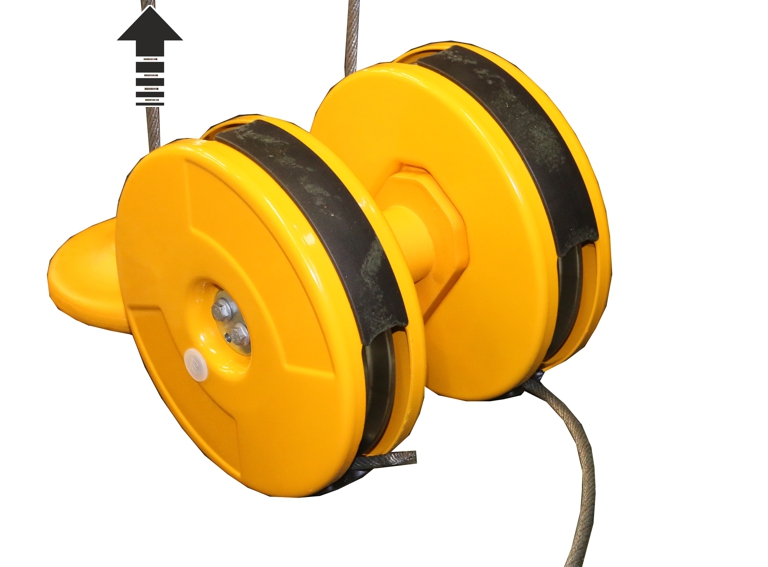
- Fit the bottom block.
- Pull the wire rope out of the bottom block.
Disassembling the cable guide
Self-tapping screw
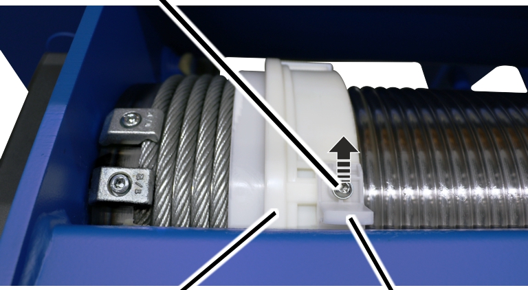
- Allow the wire rope to run off the cable drum using the motor.
Several wire rope windings should remain on the cable drum.
- Unscrew the rope guide runner.
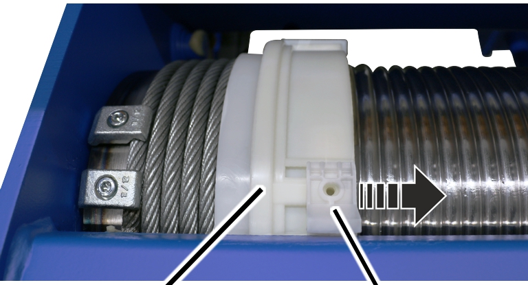
- Push the rope guide runner away to one side of the rope guide ring.
- The rope guide ring can now be turned freely on the cable drum.
Hexagon head screwJoining element
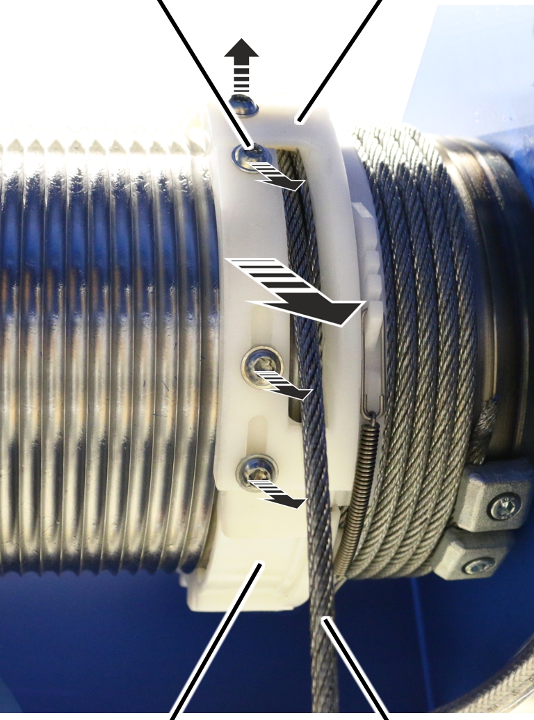
- Turn the rope guide ring so that the screws (4x) are easily accessible (e.g. upwards).
- Loosen screws (4x).
- Remove the joining element and unthread it from the wire rope.
Cable drumRidge
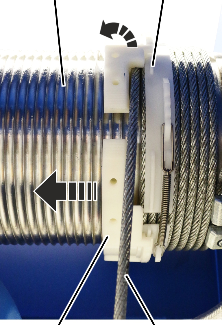
- Force the rope guide ring apart and pull it inwards and off the cable drum.
RidgeRope tension ring
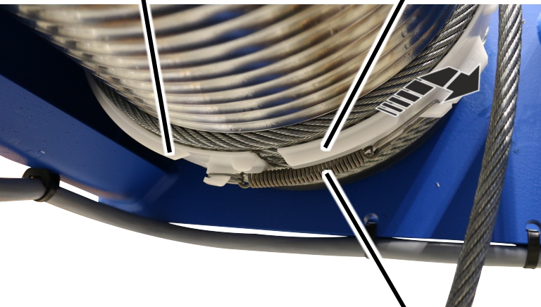
- Remove the tension spring from the rope tension ring.
- Force the rope tension ring apart and pull it inwards and off the cable drum.
- The cable guide has now been disassembled. The wire rope is now lying loose on the cable drum.
Removing the wire rope from the cable drum
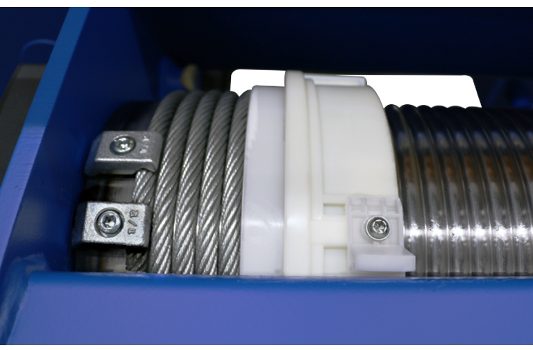
Cable drumEnd clamps
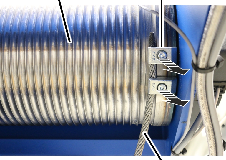
- Allow the wire rope to run off the cable drum using the motor.
- Release the end clamps (2x).
- Completely remove the wire rope from the cable drum.
Cleaning and lubricating the cable drum
- Clean the cable drum.
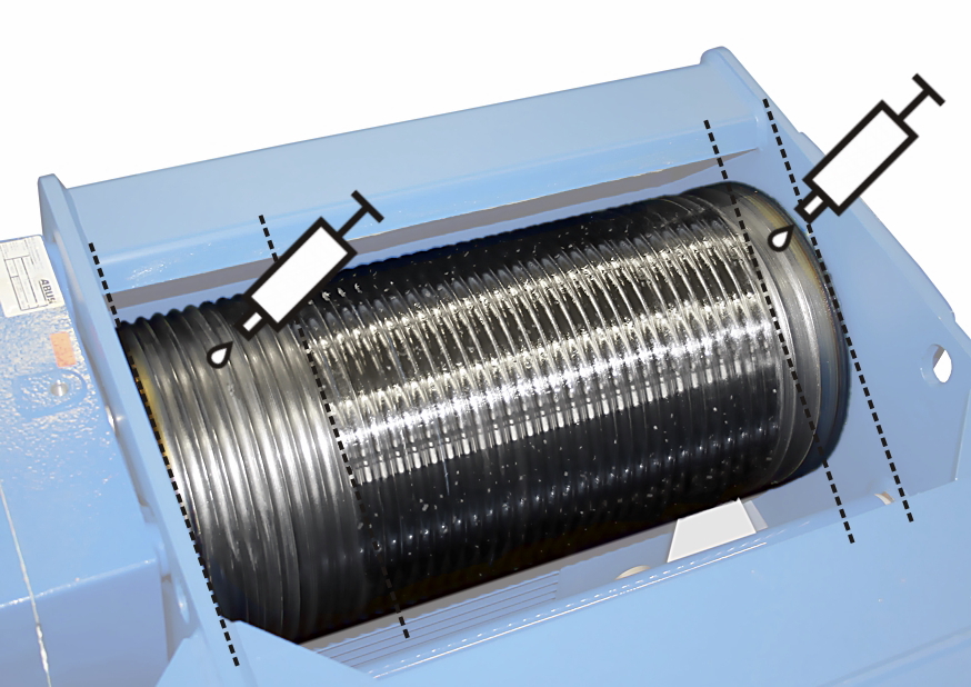
- Lubricate the cable drum from the start to about the 8th or 10th turn.
- Lubricate the cable drum behind the last turn.
Lubricant: “Molykote PG-75”. For details, see “Lubricants”.
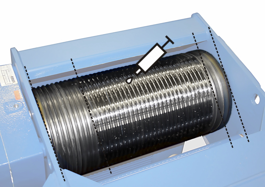
- Lubricate the cable drum behind the 8th/10th turn up to the last turn.
Lubricant: “Chainlife S”. For details, see “Lubricants”.
Fastening the wire rope to the cable drum
Cable drumFillister-head screw
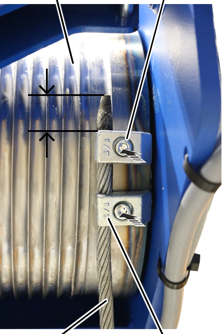
- Roll out the wire rope without twisting it.
- Thoroughly clean the fillister-head screws of the end clamps.
The fillister-head screws were previously bolted with a thread lock coating or a thread lock. The residues must be completely removed before the fillister-head screw may be used again.
The thread lock coating and thread lock are single-use only.
- Push the wire rope under the end clamps far enough that the rope protrusion is about 30 mm.
- Tighten the end clamps (2x) with fillister-head screws and secure with (medium strength) thread lock.
Size |
Fillister-head screw |
Number |
Tightening torque |
|---|---|---|---|
GM 800 |
M6x16 |
2 |
10 Nm |
GM 1000 |
M8x20 |
2 |
25 Nm |
GM 2000 |
M8x20 |
2 |
25 Nm |
GM 3000 |
M8x20 |
2 |
25 Nm |
- Pull the wire rope taut and use the motor to wind it onto the cable drum by 6 to 8 turns, ensuring it is taut and not twisted.
Installing the cable guide
Ridge
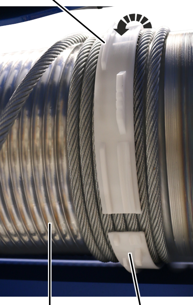
- Turn the rope tension ring so that the ridge is facing the hoisting gear.
- Force the rope tension ring apart and guide it over the wire rope on the cable drum.
RidgeRope tension ring
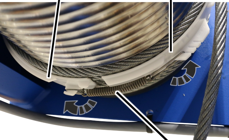
- Hook the tension spring into one of the notches so that the rope tension ring is firmly seated on the wire rope but can still be turned freely.
Cable drumRidge
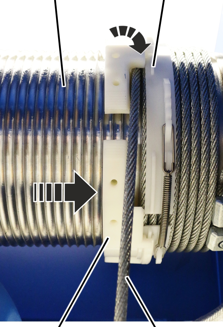
- Grease the groove of the rope guide ring.
Lubricant: “Molykote PG-75”. For details, see “Lubricants”.
- Force the rope guide ring apart and push it over the cable drum.
- Place the rope guide ring with the groove into the ridge on the rope tension ring.
- Place the rope guide ring with the threaded segments into the free section of the cable drum.
- Check that both ends of the rope guide ring lie in the same groove of the cable drum.
The ends of the rope guide ring must be aligned.
Self-tapping screwJoining element
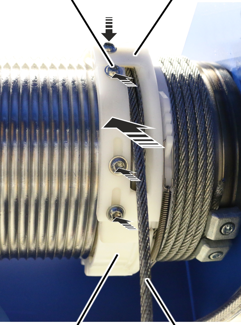
- Thread the joining element onto the wire rope.
- Push the joining element upwards and place it onto the rope guide ring.
- Tighten the joining element with self-tapping screws M6x16 (4x). 5 Nm.
When doing this, first secure the upper screws which do not lie in the elongated hole.
Installing the rope guide runner
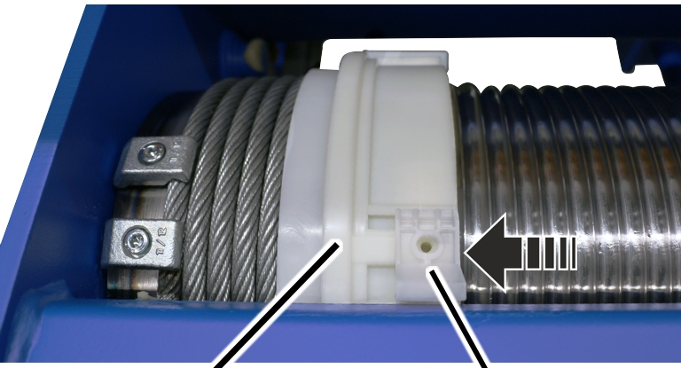
- Put the rope guide runner on the drum housing and push it laterally into the rope guide ring.
Self-tapping screw
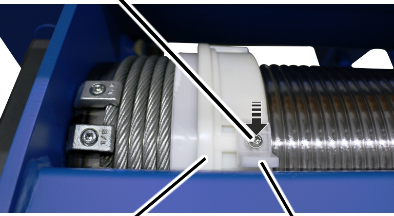
- Screw on the rope guide runner with the self-tapping screw M6x16. 5 Nm.
Reeving the wire rope
- For reeving 2/1: pull the wire rope from the cable drum and through the bottom block, without twisting it.
- For reeving 4/1: Pull the wire rope from the cable drum and through the bottom block, without twisting it, and through the deflection roller and once again through the bottom block.
Installing the fixed point
Only with exchange of rope socket with rope wedge
Installing the rope socket
Measurement boltFixed point crosshead
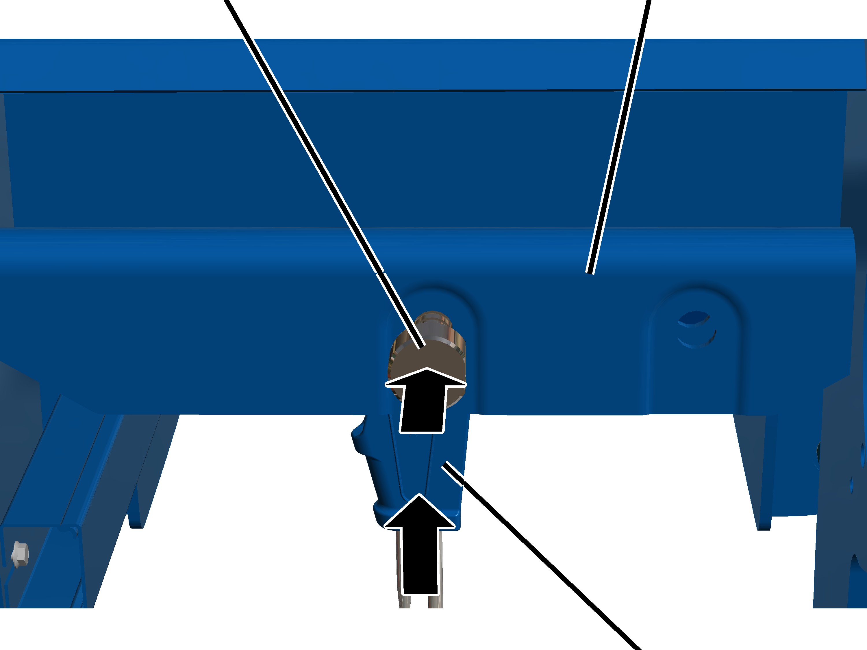
- Push the rope socket into the fixed point crosshead.
Note the marking on the fixed point crosshead.
- Push the measurement bolt through the fixed point crosshead and the rope socket.
The arrow on the measurement bolt must point downward!
Measurement boltRib screw
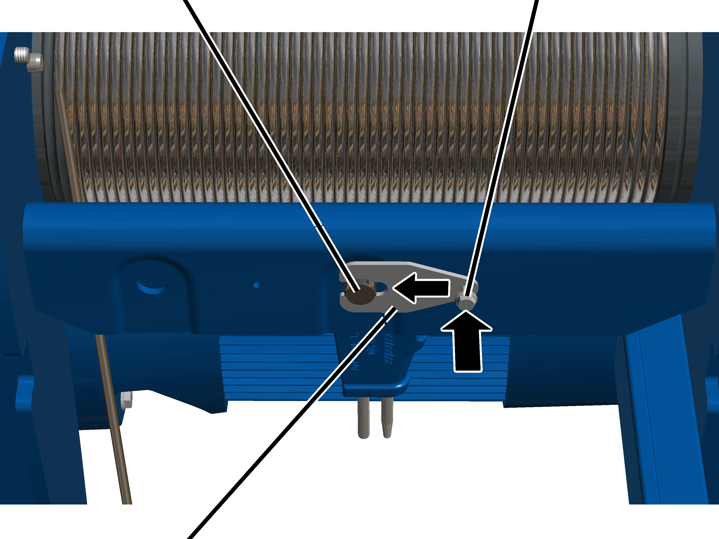
- Slide the mount onto the measurement bolt.
The mount must allow itself to be inserted into the groove of the measurement bolt without tension.
The measurement bolt should not have any pretension!
- Screw on the mount with the rib screw M6x12. 19 Nm.
Fixed point crossheadRope socket
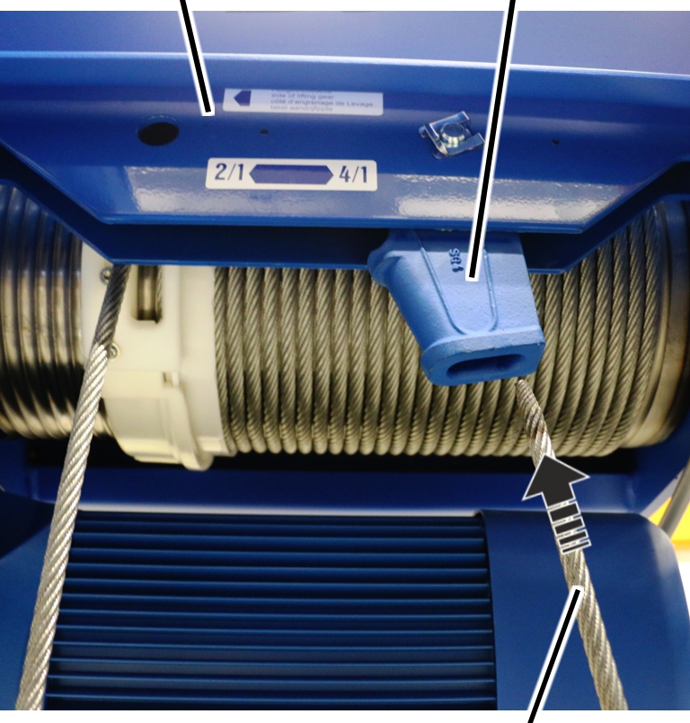
- Check the lubrication of the rope socket and grease it if necessary.
Lubricant: “High temperature paste PBC 1574”. For details, see “Lubricants”.
- Push the end of the wire rope into the rope socket from below.
Rope socketFixed point crosshead
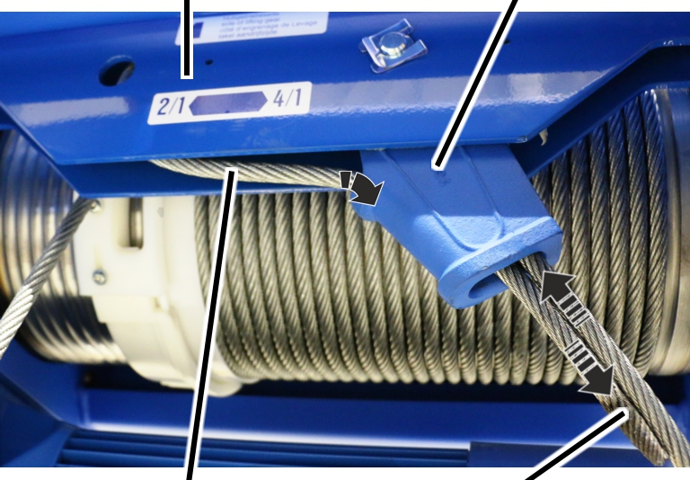
- Push the end of the wire rope into the rope socket from above so that a loop forms.
The end of the wire rope protrudes below about 150 mm out of the rope socket.
Rope wedgeRope socket
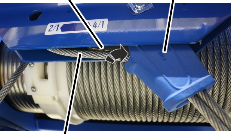
- Place the rope wedge in the loop.
Rope socket
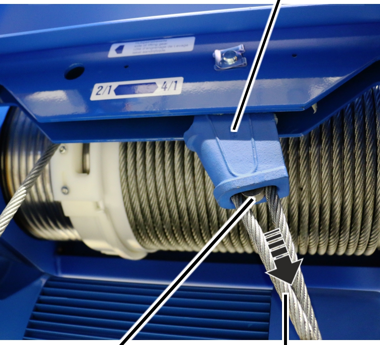
- Give the wire rope a jolting tug.
- The rope wedge slips into the rope socket and the wire rope is tightly clamped.
Dead end rope grip
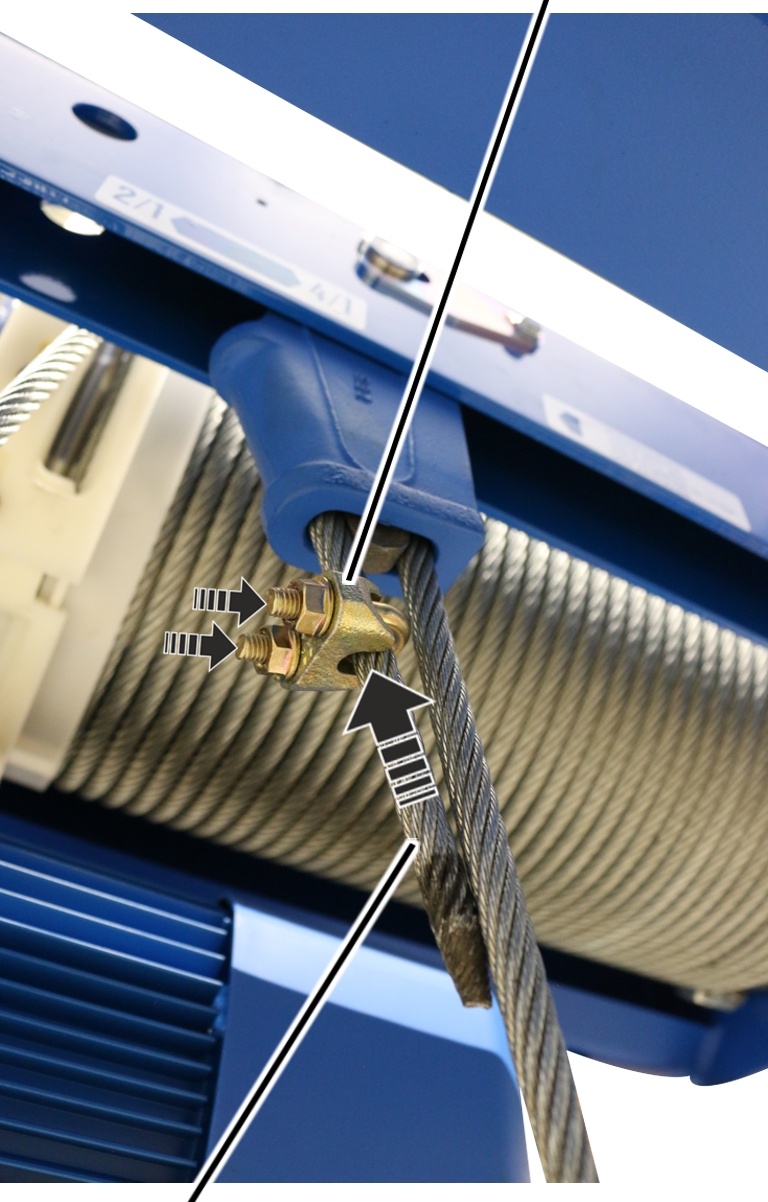
- Push the dead end rope grip over the end of the wire rope.
The dead end rope grip must be mounted, depending on the size and rope thickness, with the dimension from the following table, under the rope socket:
Size |
Rope thickness |
Distance from rope socket approx. |
|---|---|---|
GM 800 |
6.5 mm |
6 mm to 13 mm |
GM 1000 |
8 mm |
8 mm to 16 mm |
GM 2000 |
9 mm |
9 mm to 18 mm |
GM 3000 |
11 mm |
11 mm to 22 mm |
- Screw the dead end rope grip tight.
Size |
Rib nut |
Tightening torque |
|---|---|---|
GM 800 |
M6 |
5 Nm |
GM 1000 |
M8 |
10 Nm |
GM 2000 |
M8 |
10 Nm |
GM 3000 |
M8 |
10 Nm |
Installing the rope guard on the bottom block
On all openings on the bottom block:
Connecting profile
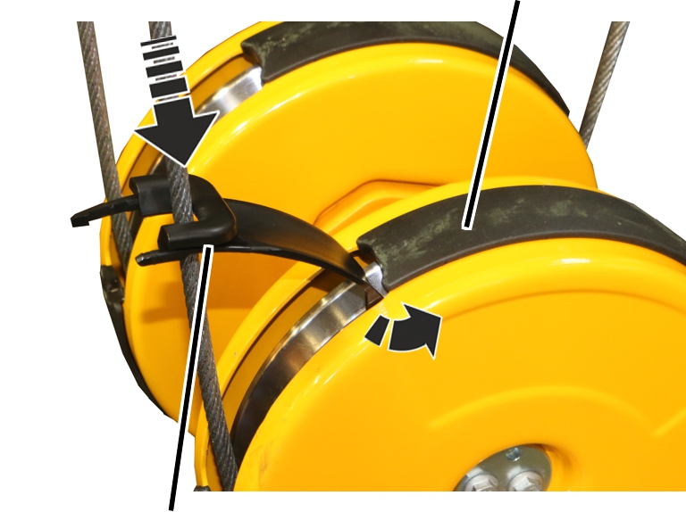
- Hold the rope guard on the wire rope as shown in the figure.
- Push the rope guard down along the wire rope with the front fork and bring the rear end under the connecting profile.
Rope guardBottom block cover
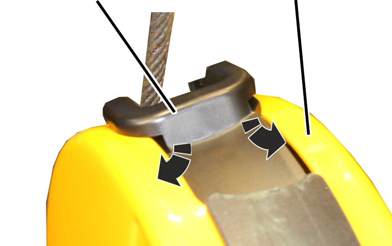
- First push the rope guard on the side with the short bracket into the bottom block cover.
- Then push the rope guard on the side with the long bracket into the bottom block cover.
Rope guard
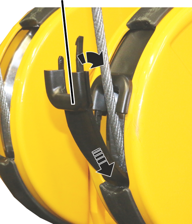
- Push the second rope guard at the bottom into the connecting profile.
- Push the rope guard downwards behind the connecting profile and attach it above on the wire rope.
- First push the rope guard on the side with the short bracket into the bottom block cover.
- Then push the rope guard on the side with the long bracket into the bottom block cover.
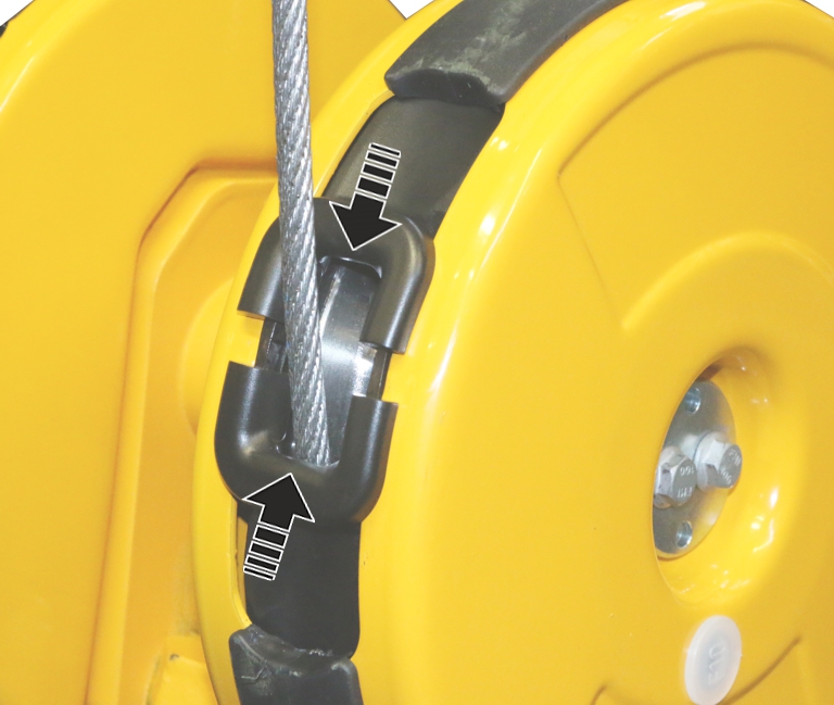
- Connect the brackets of the rope guards (2x) and push them together.
- A snapping sound can be heard.
Completing wire rope replacement
- Use the motor to wind up the wire rope completely.
Only with ABUControl
If ABUControl is installed for the wire rope hoist, refer to the “Exchanging the wire rope” section of the “ABUControl” product manual to complete the rope change.
Further steps are then described in this product manual.
Only with ABUS electrics 3 with contactor control or ABULiner
Installing the hoist limit switch
- Move the load hooks to the position you noted previously.
ShaftBearing flange
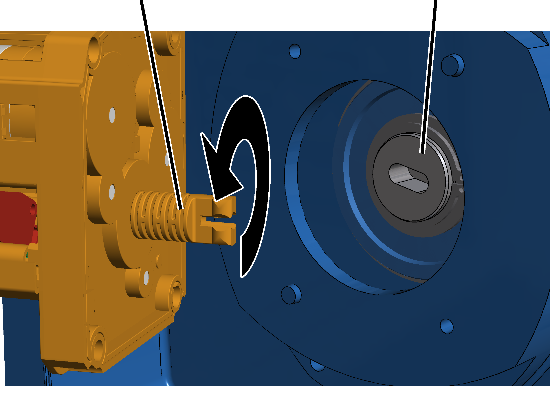
- Open the housing cover of the hoist limit switch enclosure on the cable drum.
- Rotate the shaft of the gear limit switch so that it matches the elongated hole in the bearing flange of the cable drum.
Plastic screws B6, 3x25
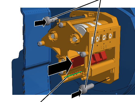
- Insert the gear limit switch with the shaft in the elongated hole on the bearing flange and guide it onto the two pins.
- Screw the gear limit switch tight with the plastic screws B6, 3x25. 3 Nm.
Connecting the hoist limit switch
- Plug in the connector of the connection cable on the cam switch PCB.
- Close the housing cover.
If the switching points have moved:
Normally, the adjustment of the hoist limit switch after replacing the wire rope can in many cases be omitted, since the position of the load hook was previously measured and then travelled to again. In special cases (e.g. if the wire rope is severely damaged or has been incorrectly rolled onto the cable drum), the switching points may need to be readjusted.
- Reset switching points for the bottom hoist limiter, the top hoist limiter and the backup limiter.
With ABUS electrics 3 with contactor control: see product manual “ABUS gear limit switch”.
With ABUS electrics 3 with ABULiner: see product manual “Frequency converter control of the lifting speed for ABUS electrics 3”.
Checking the rope wedge protrusion
- Referring to the following table, suspend the load from the load hooks, raise it and load the wire rope this way.
Size |
Reeving 2/1 |
Reeving 4/1 |
|---|---|---|
GM 800 |
800 kg |
1600 kg |
GM 1000 |
1250 kg |
2500 kg |
GM 2000 |
1600 kg |
3200 kg |
GM 3000 |
2000 kg |
4000 kg |
The details provided in the table are guide values, which should be observed with a tolerance of ±20 %.
Observe the maximum load capacity of the wire rope hoist and do not exceed it!
- Measure the rope wedge protrusion and check whether the dimensions specified in the table have been complied with.
Size |
Maximum rope wedge protrusion |
Minimum rope wedge protrusion |
|---|---|---|
GM 800 |
19 mm |
18 mm |
GM 1000 |
4 mm |
3 mm |
GM 2000 |
2 mm |
0 mm |
GM 3000 |
18 mm |
16 mm |
Exchanging the fixed point crosshead with rope socket and rope wedge
If the fixed point crosshead, the rope socket or the rope wedge are damaged, they must be replaced.
Disassembling the fixed point crosshead
SL safety clip
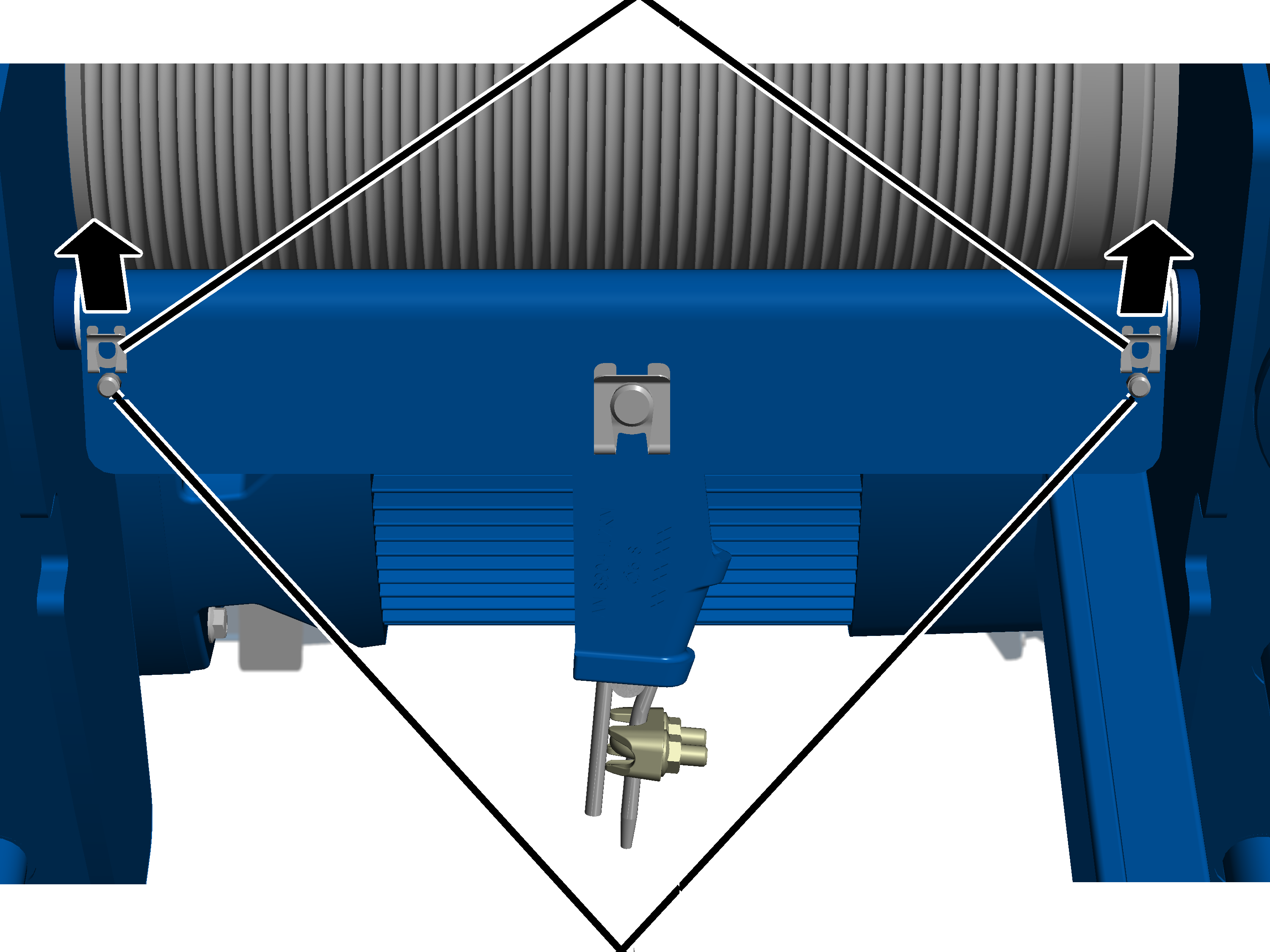
- Pull the SL safety clips (2x) from the bolts.
Bolt
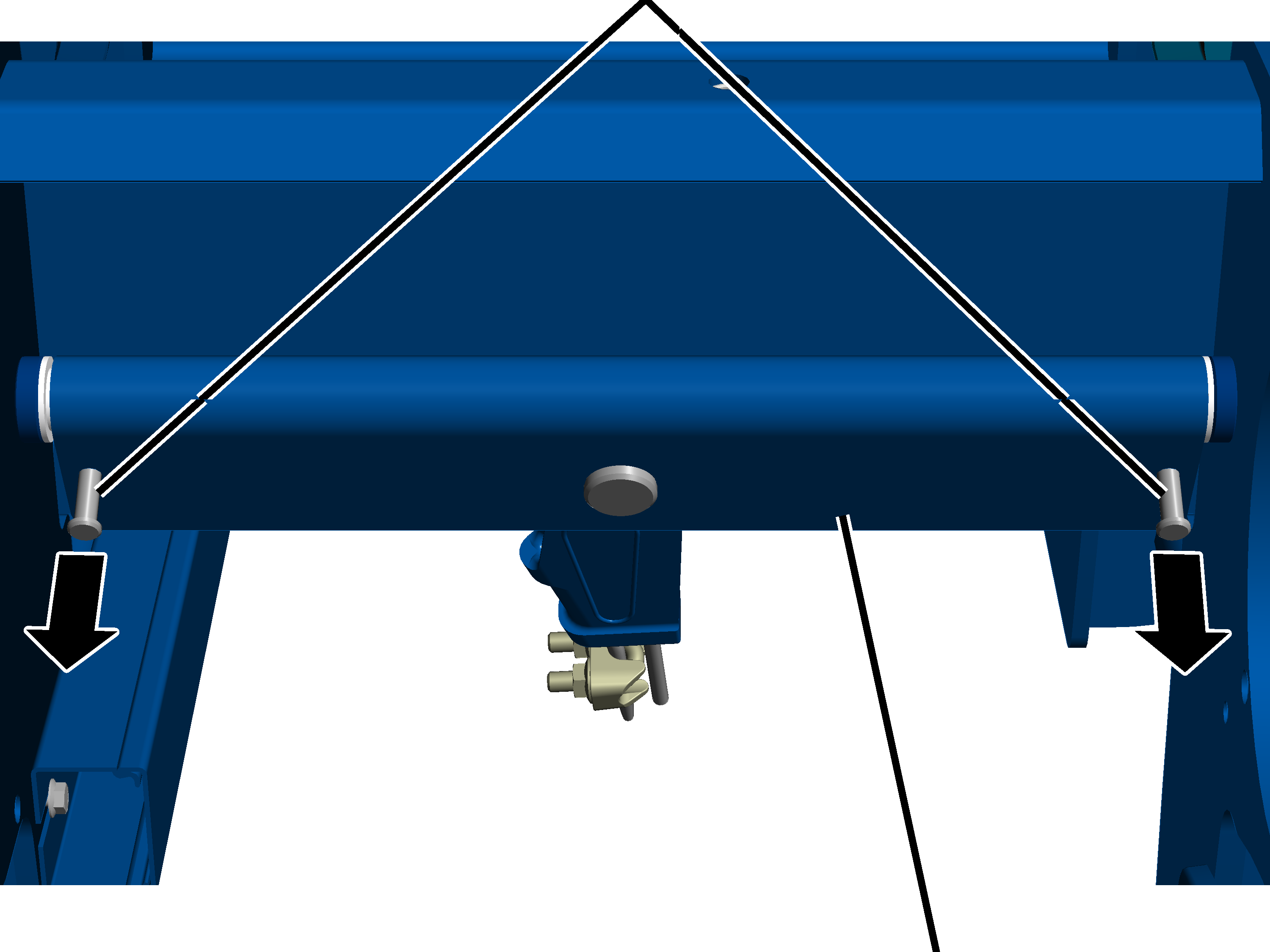
- Pull the bolts (2x) out of the fixed point crosshead.
Fixed point crosshead
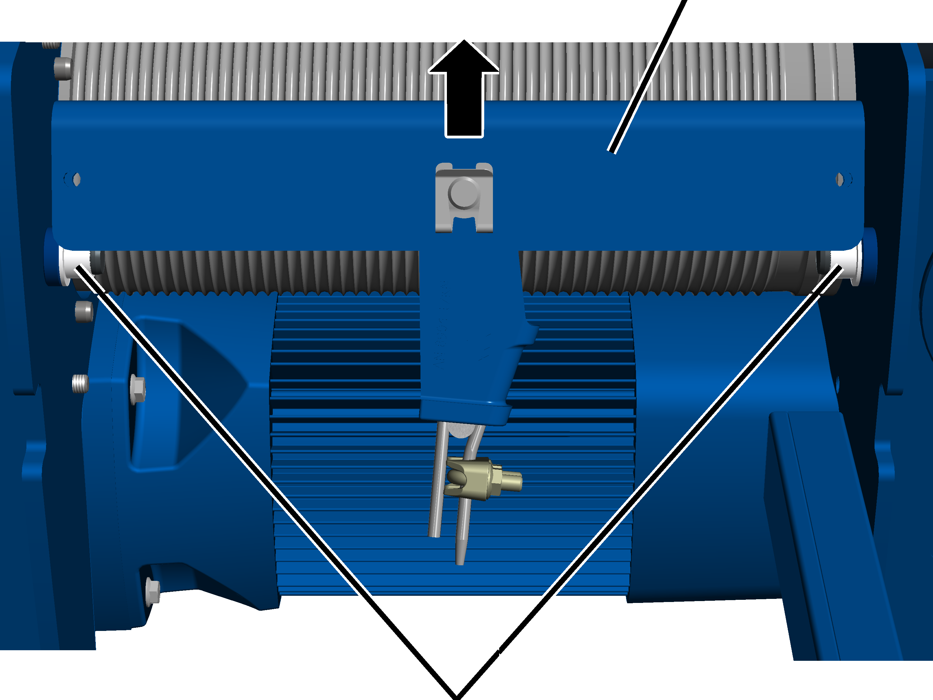
- Lift the fixed point crosshead from the bearing bushes.
Disassembling the rope socket
MountRib screw
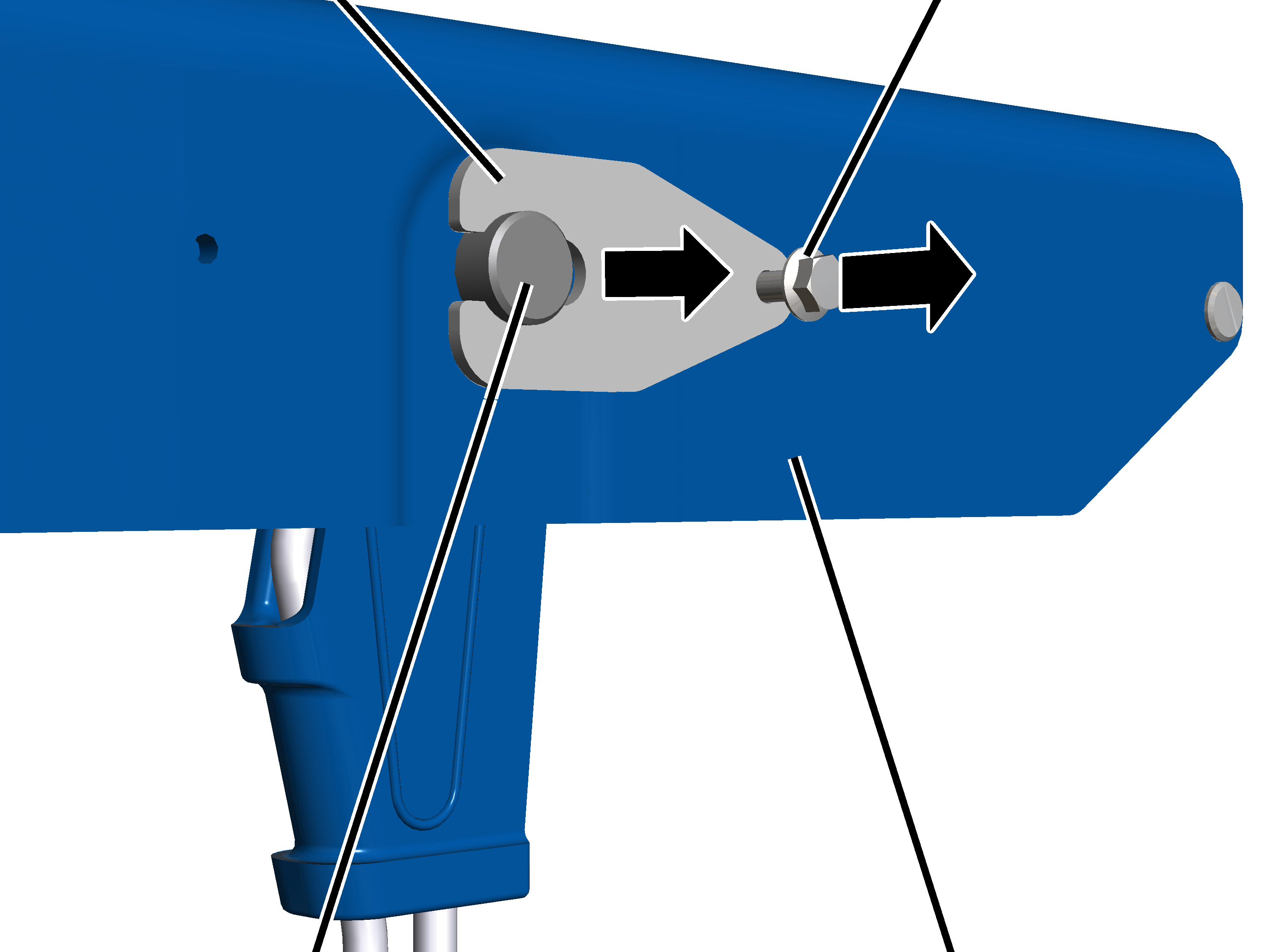
- Release rib screw M6x12.
- Slide the mount from the measurement bolt.
Fixed point crossheadMeasurement bolt
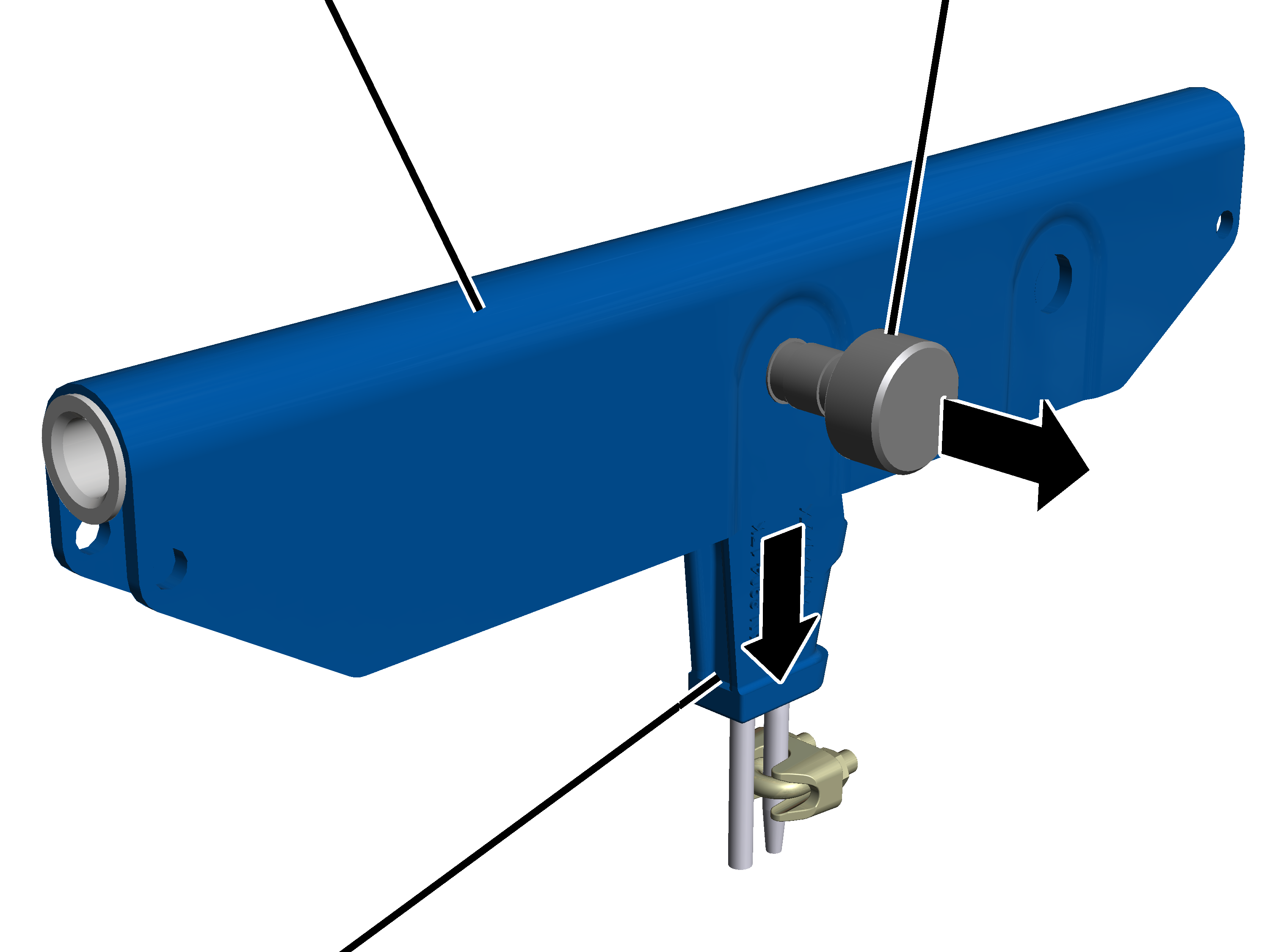
- Pull the measurement bolt out of the fixed point crosshead and the rope socket.
- Pull the rope socket out of the fixed point crosshead.
Removing the rope wedge
Rope socket
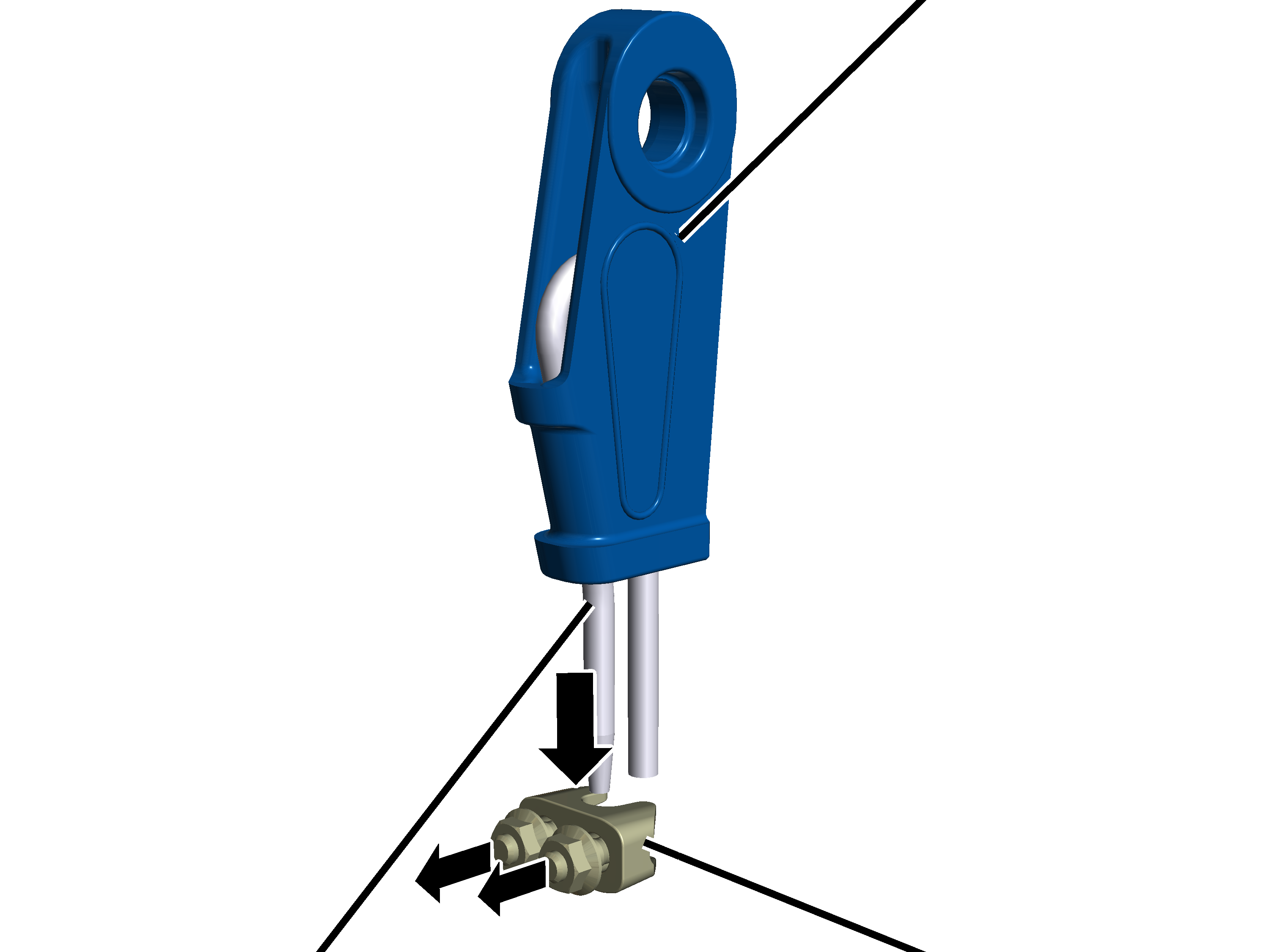
- Release the rib nuts on the dead end rope grip.
- Pull the dead end rope grip from the end of the wire rope.
Rope wedge
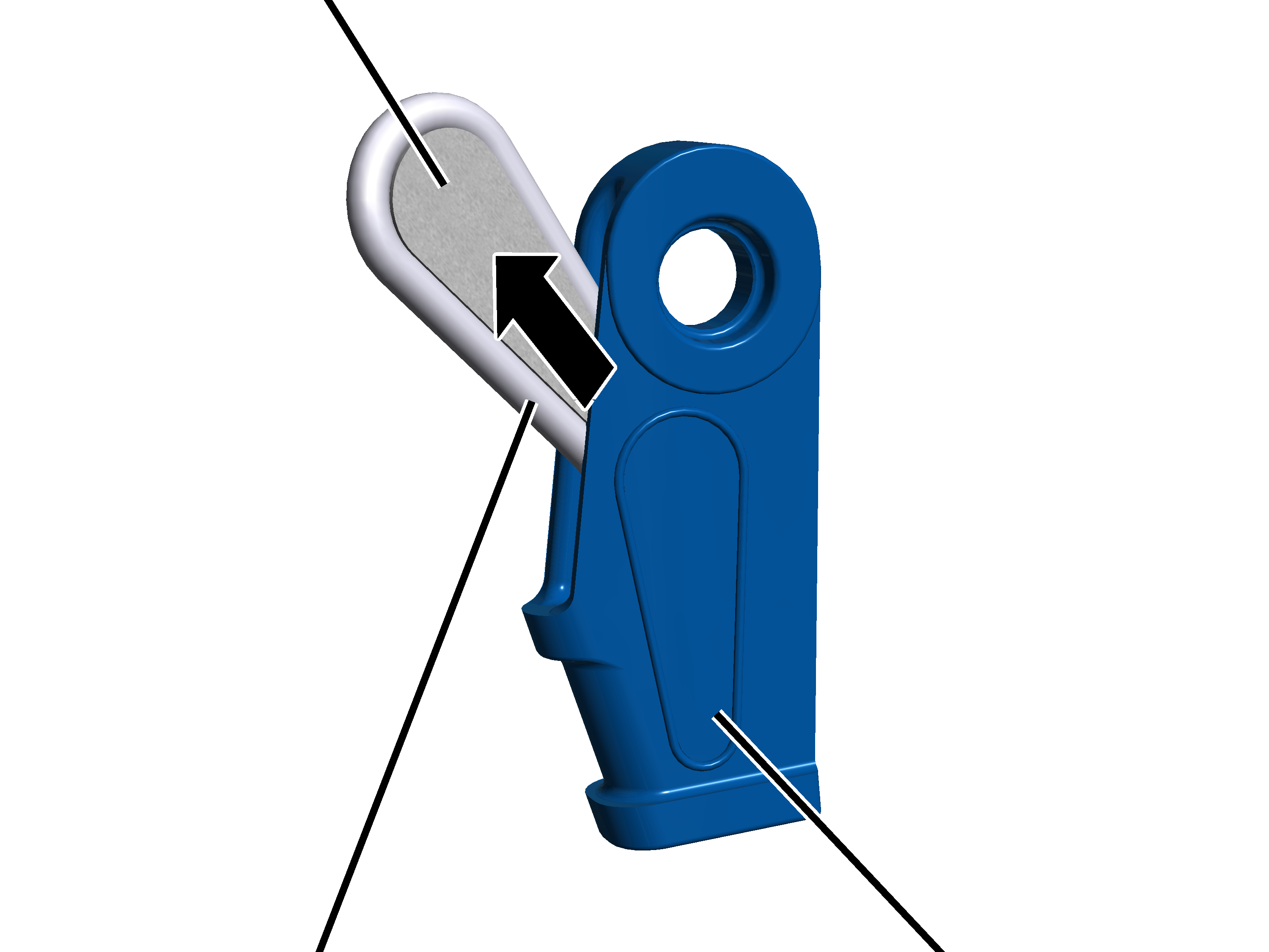
- Pull the rope wedge with wire rope out of the rope socket.
Installing the rope wedge
Rope wedge
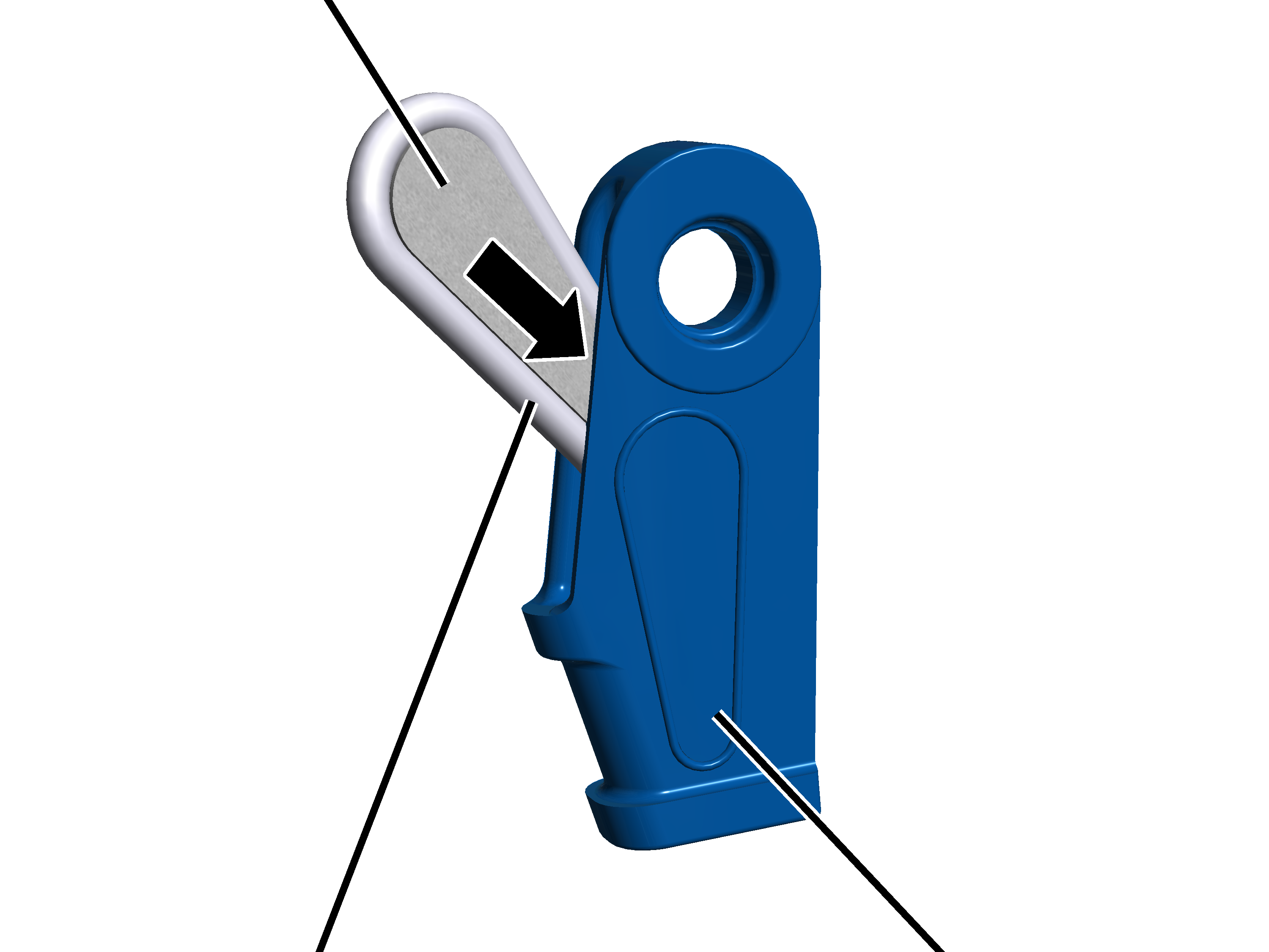
- Lay the end of the wire rope around the rope wedge.
The wire rope must lie level in the groove of the rope wedge!
- Push the rope wedge with wire rope into the rope socket and pull it to the end of the wire rope with a jolting tug.
- The rope wedge slips into the rope socket and clamps the wire rope.
Rope socket
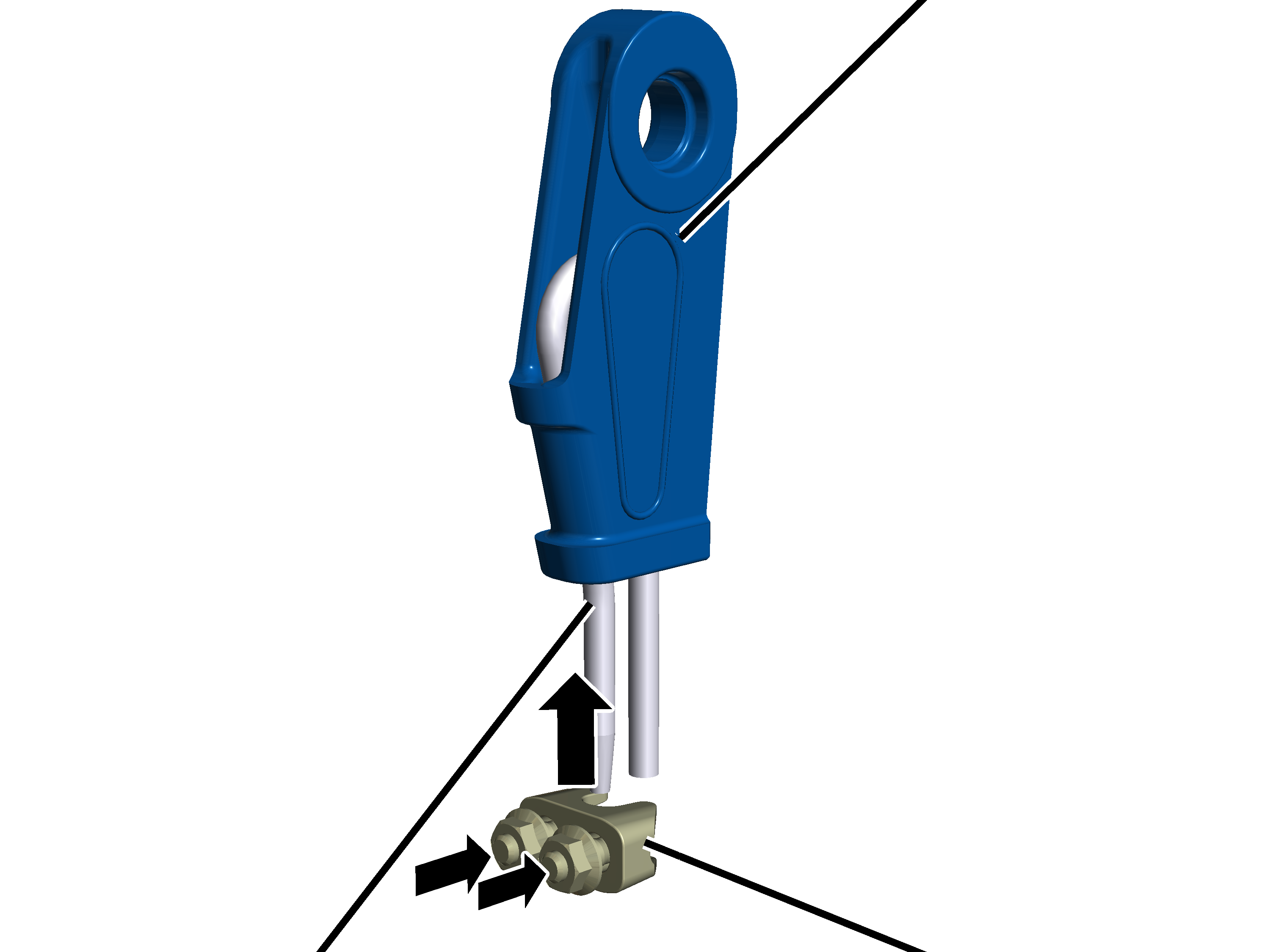
- Push the dead end rope grip onto the end of the wire rope.
- The dead end rope grip must be mounted, depending on the size and rope thickness, with the dimension from the following table, under the rope socket:
Size |
Rope thickness |
Distance from rope socket approx. |
|---|---|---|
GM 800 |
6.5 mm |
6 mm to 13 mm |
GM 1000 |
8 mm |
8 mm to 16 mm |
GM 2000 |
9 mm |
9 mm to 18 mm |
GM 3000 |
11 mm |
11 mm to 22 mm |
- Screw in rib nuts of the dead end rope grip.
Size |
Nut |
Tightening torque |
|---|---|---|
GM 800 |
M6 |
5 Nm |
GM 1000 |
M8 |
10 Nm |
GM 2000 |
M8 |
10 Nm |
GM 3000 |
M8 |
10 Nm |
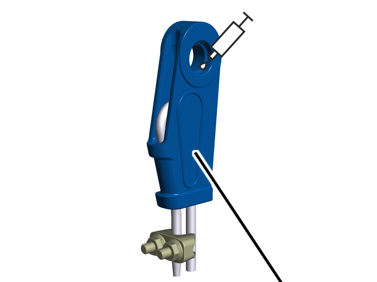
- Lubricate the rope socket.
Lubricant: “High temperature paste PBC 1574”. For details, see “Lubricants”.
Do not lubricate the measurement bolt / collar bolt or the fixed point crosshead. No lubricant should contact the fixed point crosshead.
Installing the rope socket
Fixed point crosshead
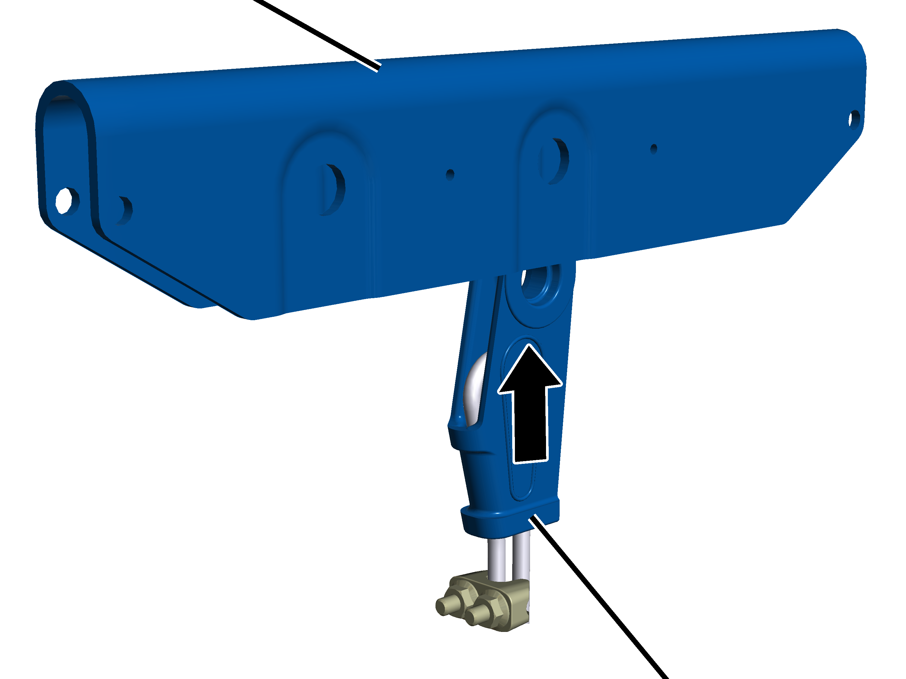
- Push the rope socket with rope wedge and wire rope into the fixed point crosshead.
Note the marking on the fixed point crosshead.
Fixed point crossheadMeasurement bolt
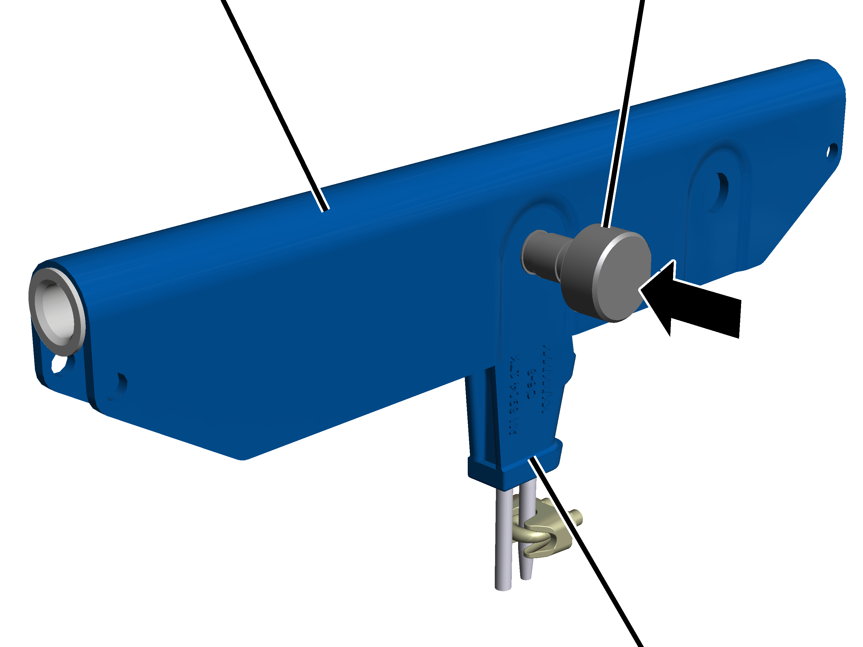
- Push the measurement bolt through the fixed point crosshead and the rope socket.
The arrow on the measurement bolt must point downward!
MountRib screw
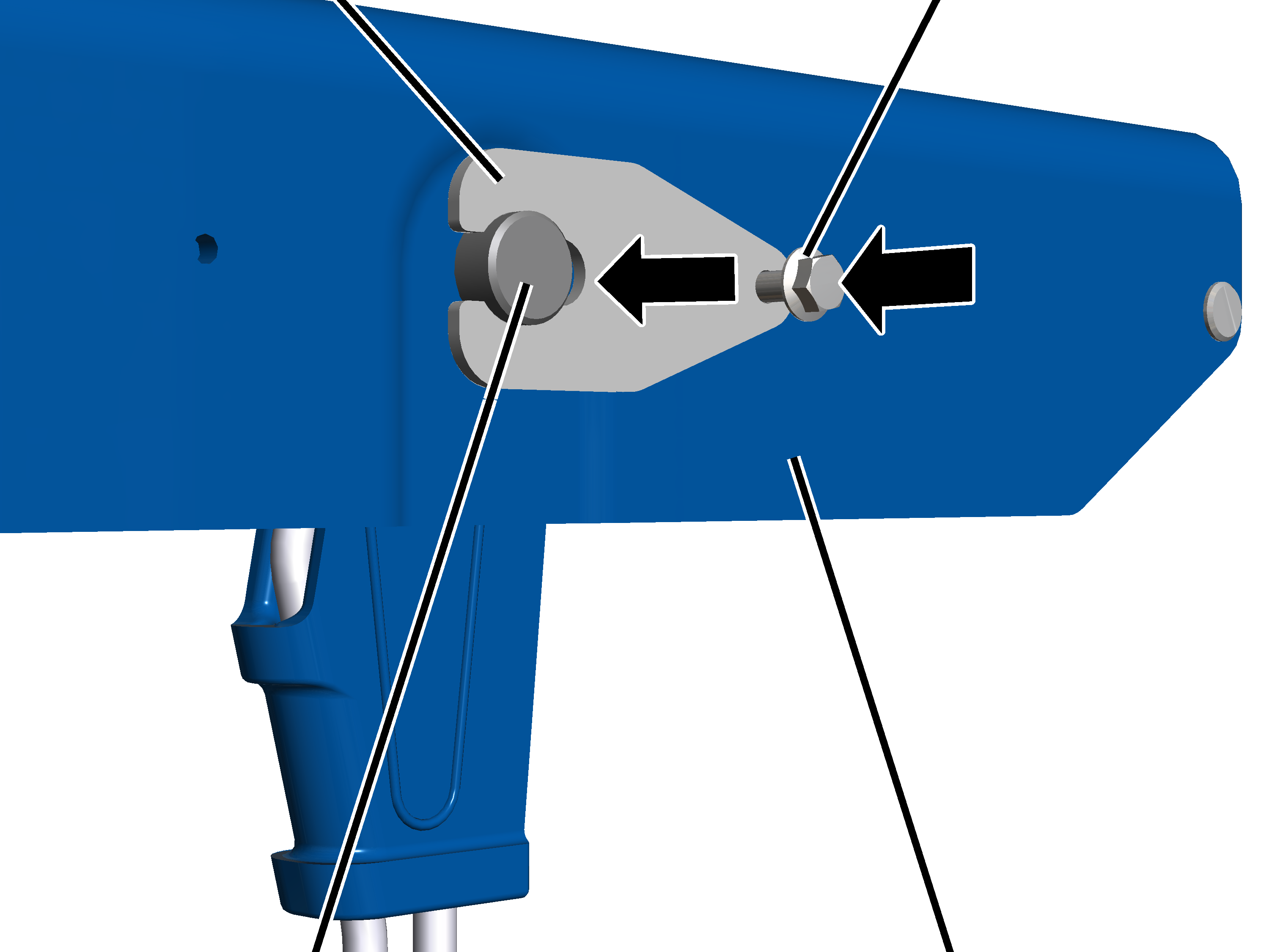
- Check the mount for deformations.
If the mount is deformed, it must be replaced.
- Slide the mount onto the measurement bolt.
The mount must allow itself to be inserted into the groove of the measurement bolt without tension.
The measurement bolt should not have any pretension!
- Screw on the mount with the rib screw M6x12. 19 Nm.
Installing the fixed point crosshead
Fixed point crosshead
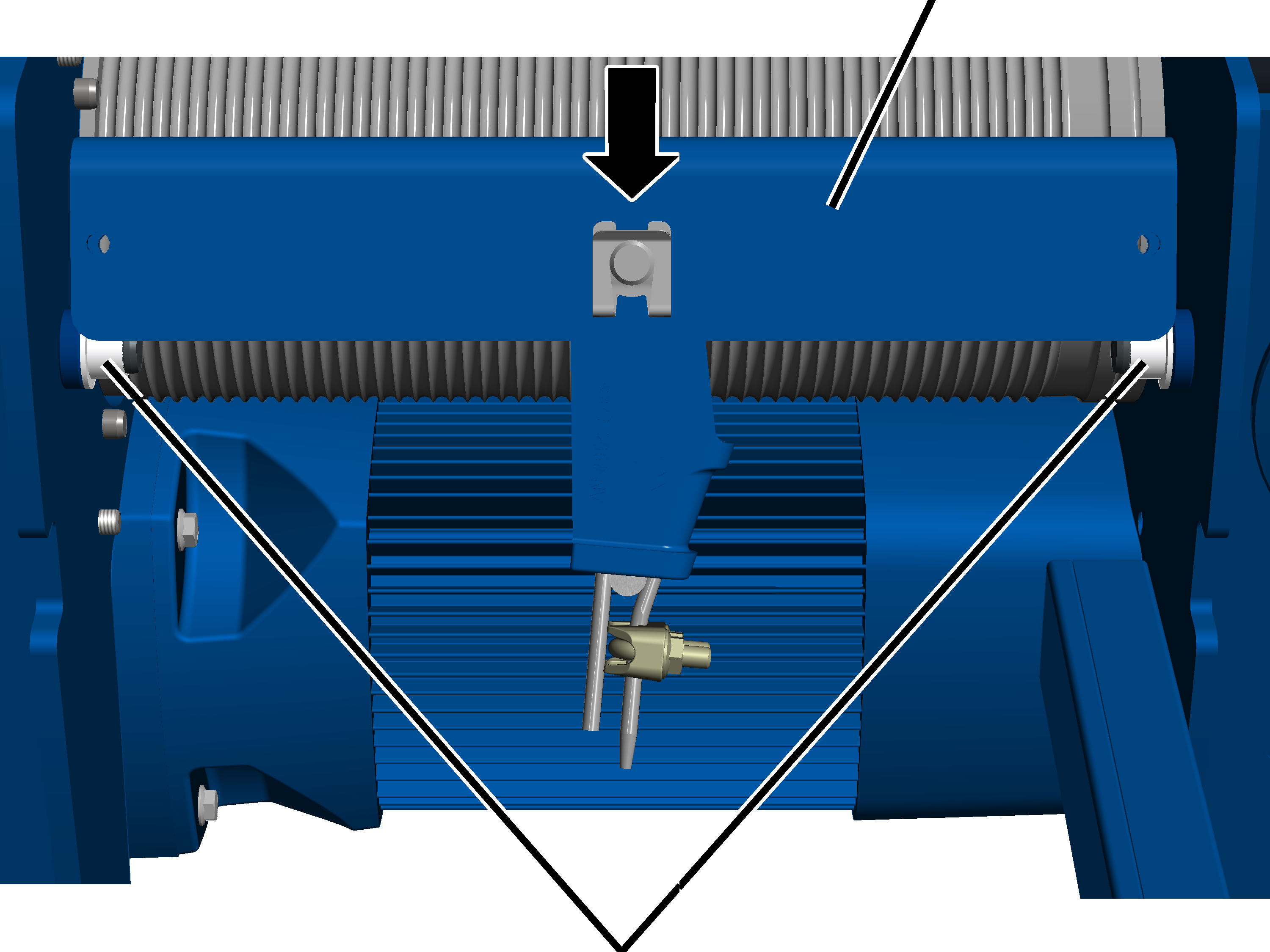
- Mount the fixed point crosshead on the bearing bushes.
When doing this, ensure that the marking on the fixed point crosshead points in the direction of the hoist drive.
Bolt
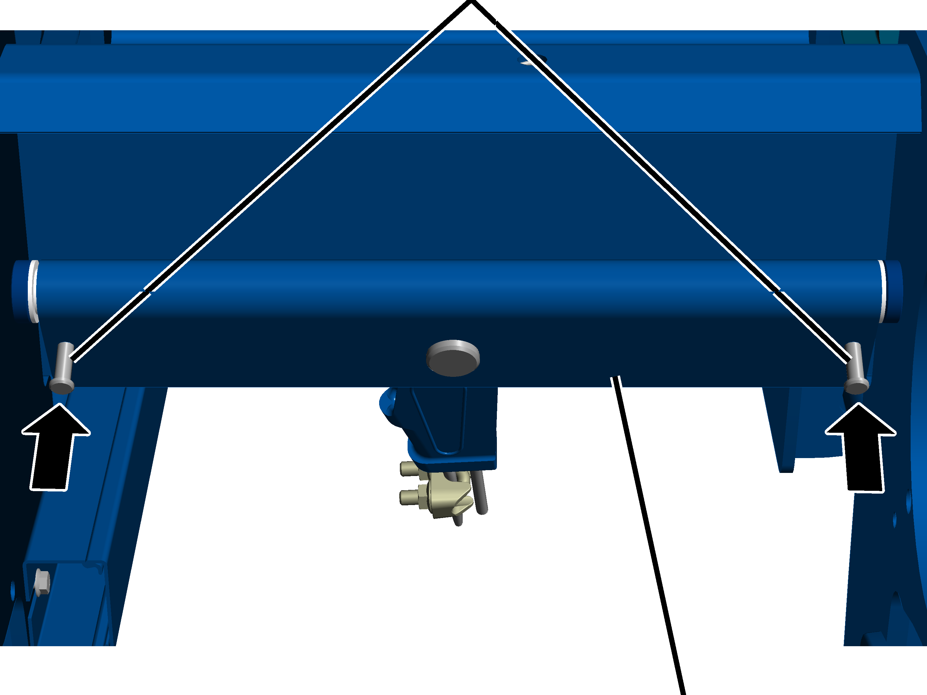
- Push the bolts (2x) into the fixed point crosshead.
SL safety clip
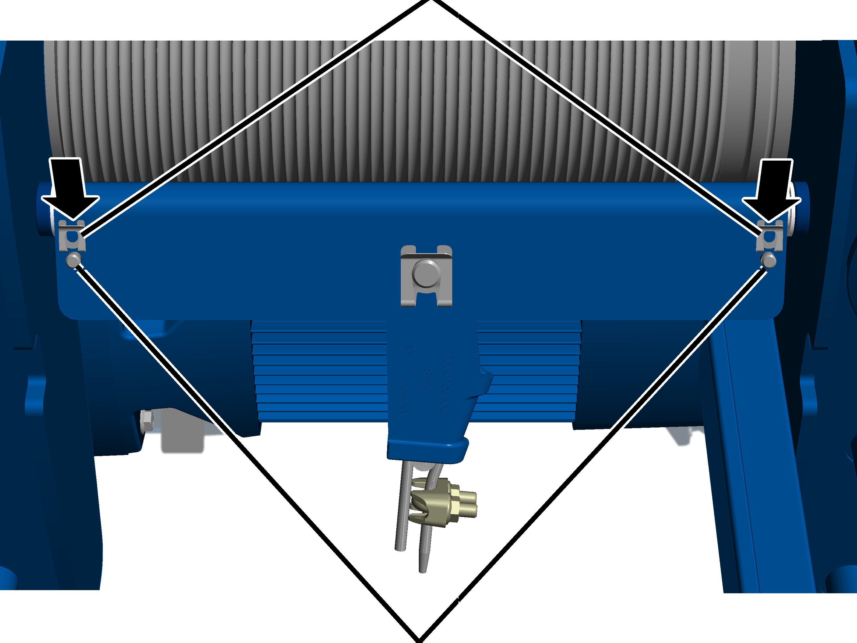
- Push the SL safety clips (2x) onto the bolts.
- Referring to the following table, suspend the load from the load hooks, raise it and load the wire rope this way.
Size |
Reeving 2/1 |
Reeving 4/1 |
|---|---|---|
GM 800 |
800 kg |
1600 kg |
GM 1000 |
1250 kg |
2500 kg |
GM 2000 |
1600 kg |
3200 kg |
GM 3000 |
2000 kg |
4000 kg |
The details provided in the table are guide values, which should be observed with a tolerance of ±20 %.
Note
Observe the maximum load capacity of the wire rope hoist and do not exceed it!
Checking the rope wedge protrusion
- Measure the rope wedge protrusion and check whether the dimensions specified in the table have been complied with.
Size |
Maximum rope wedge protrusion |
Minimum rope wedge protrusion |
|---|---|---|
GM 800 |
19 mm |
18 mm |
GM 1000 |
4 mm |
3 mm |
GM 2000 |
2 mm |
0 mm |
GM 3000 |
18 mm |
16 mm |
Exchanging the deflection roller crosshead
Only with reeving 4/1
This section only applies for a wire rope hoist with a reeving of 4/1.
If the deflection roller crosshead or its component parts are damaged, these must be replaced.
Disassembling the deflection roller crosshead
SL safety clip
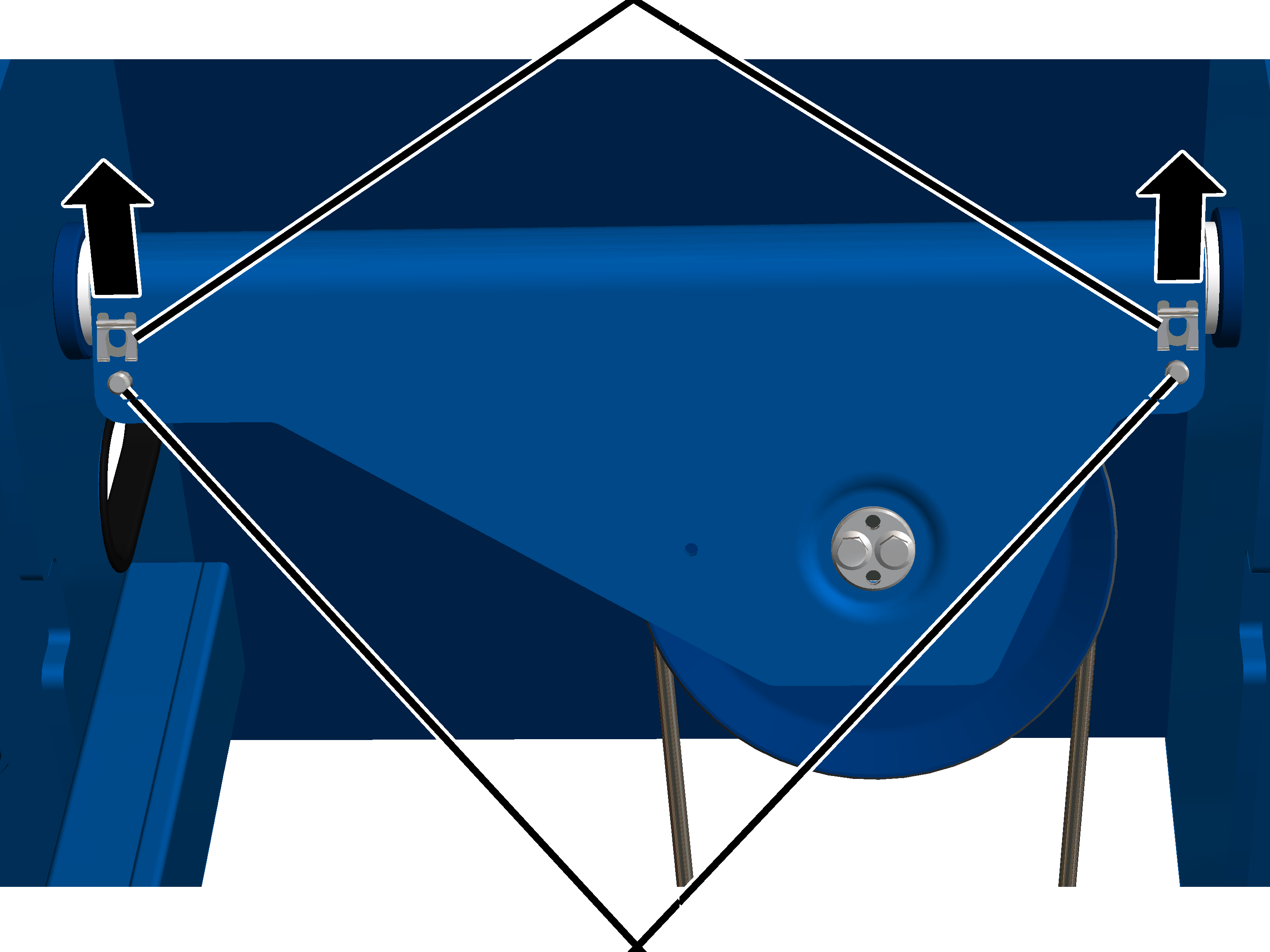
- Pull the SL safety clips from the bolts.
Bolt
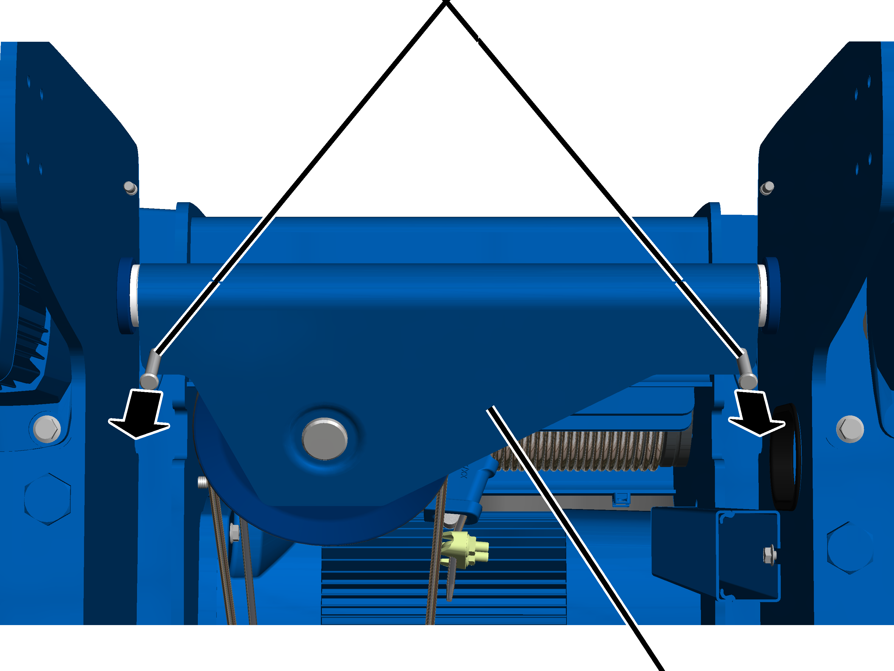
- Pull the bolts (2x) out of the deflection roller crosshead.
Deflection roller crosshead
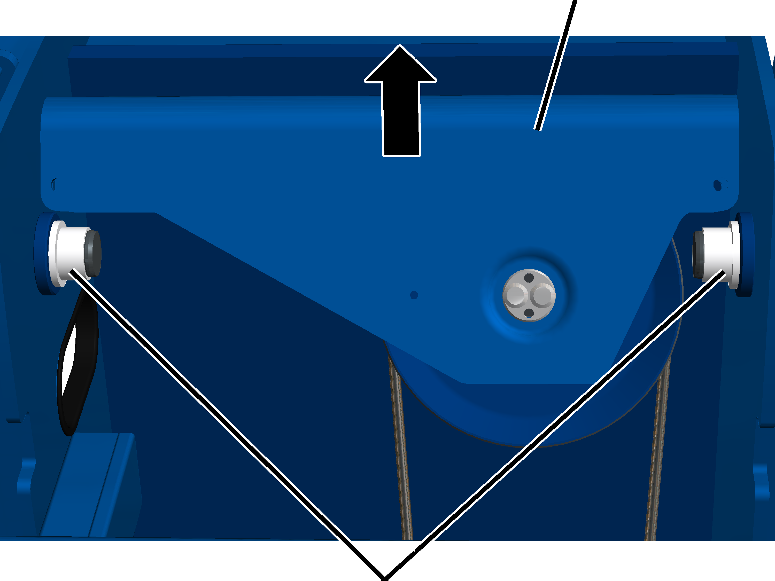
- Lift the deflection roller crosshead from the bearing bushes.
Disassembling the deflection roller
CoverRib screw
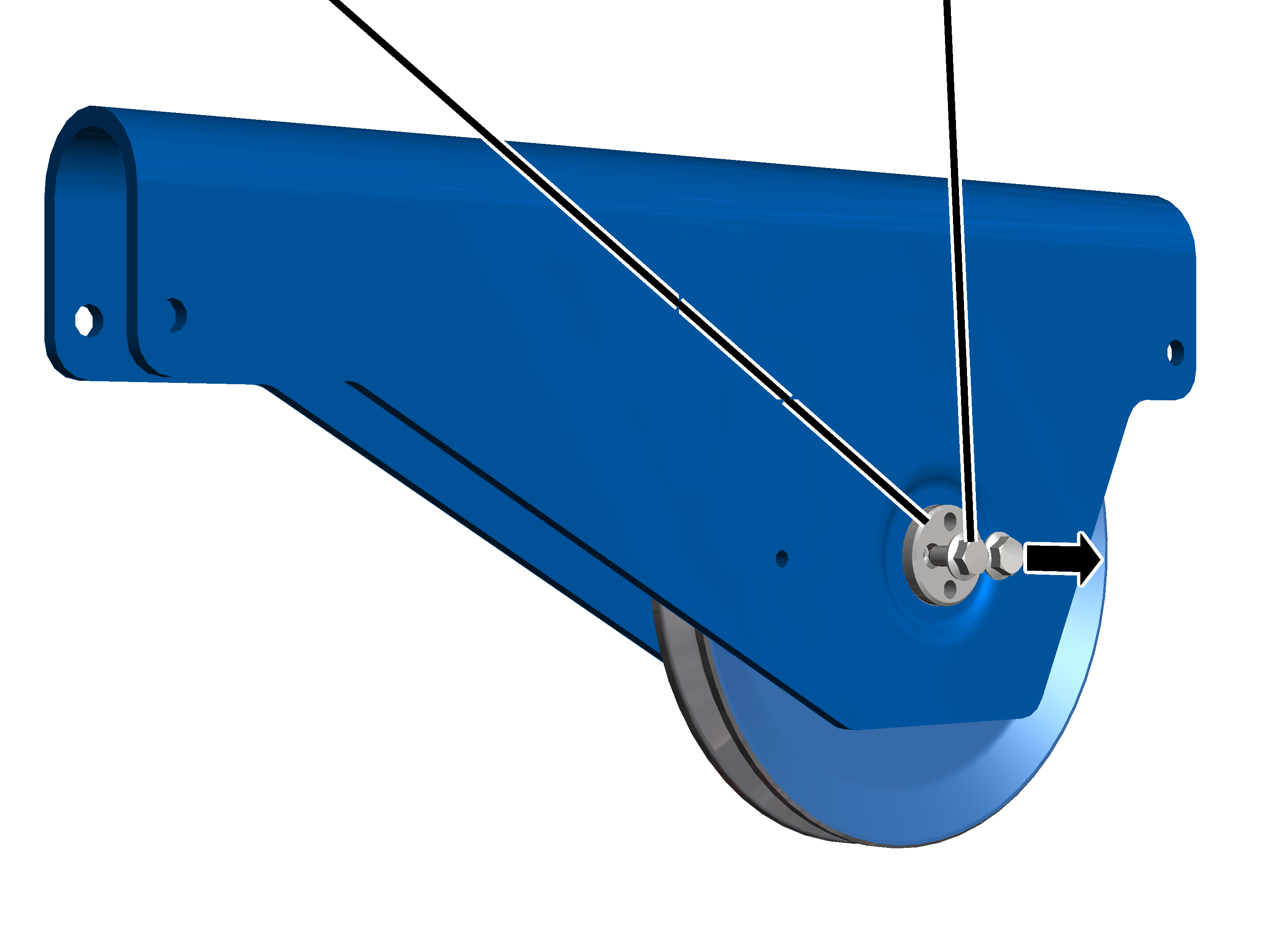
- Release the rib screws (2x) on the cover.
- Take the cover off the deflection roller crosshead.
BoltDeflection roller crosshead
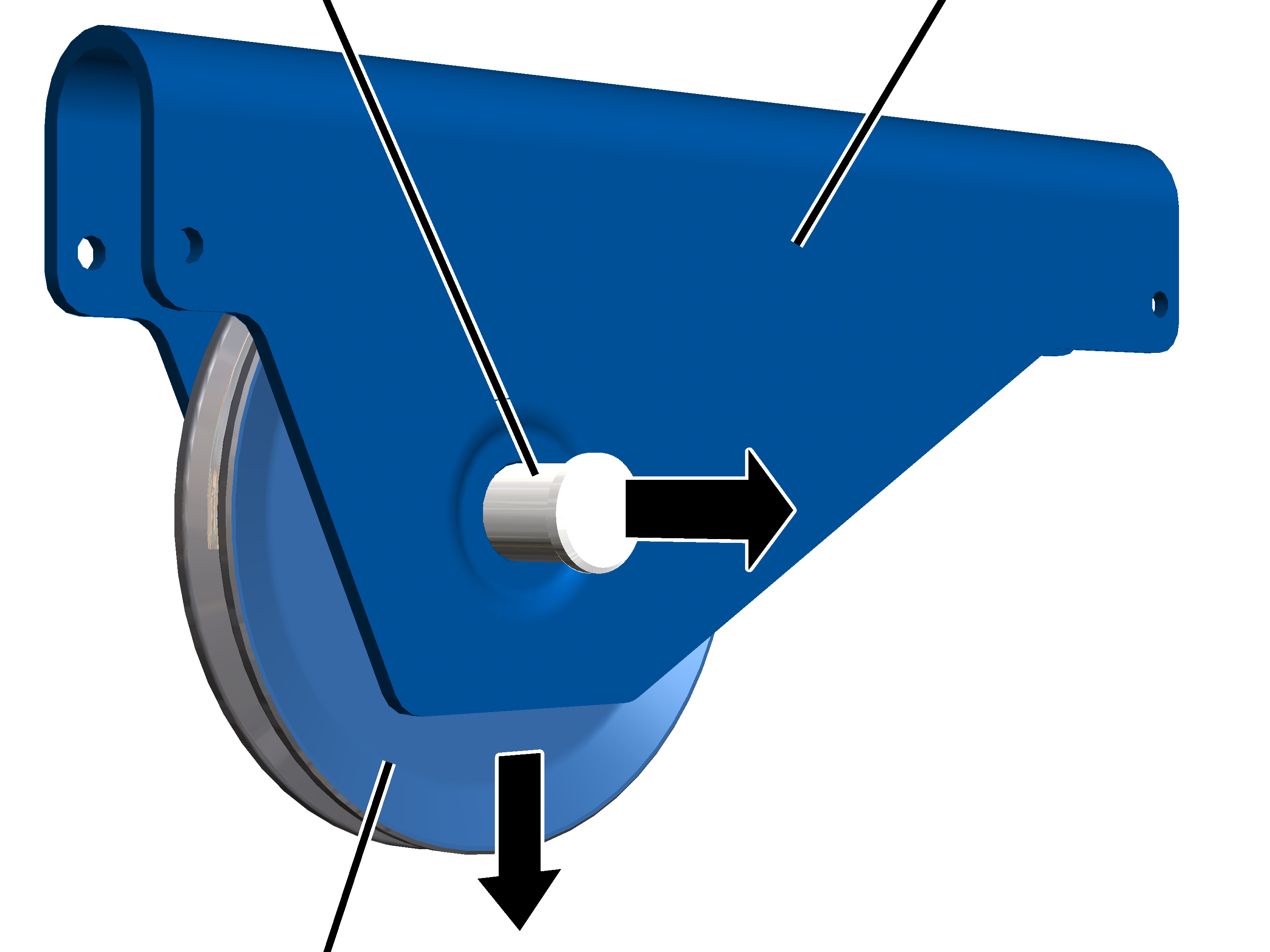
- Pull the bolt out of the deflection roller crosshead and deflection roller.
- Pull the deflection roller out of the deflection roller crosshead.
Assembling the deflection roller
Deflection roller crosshead
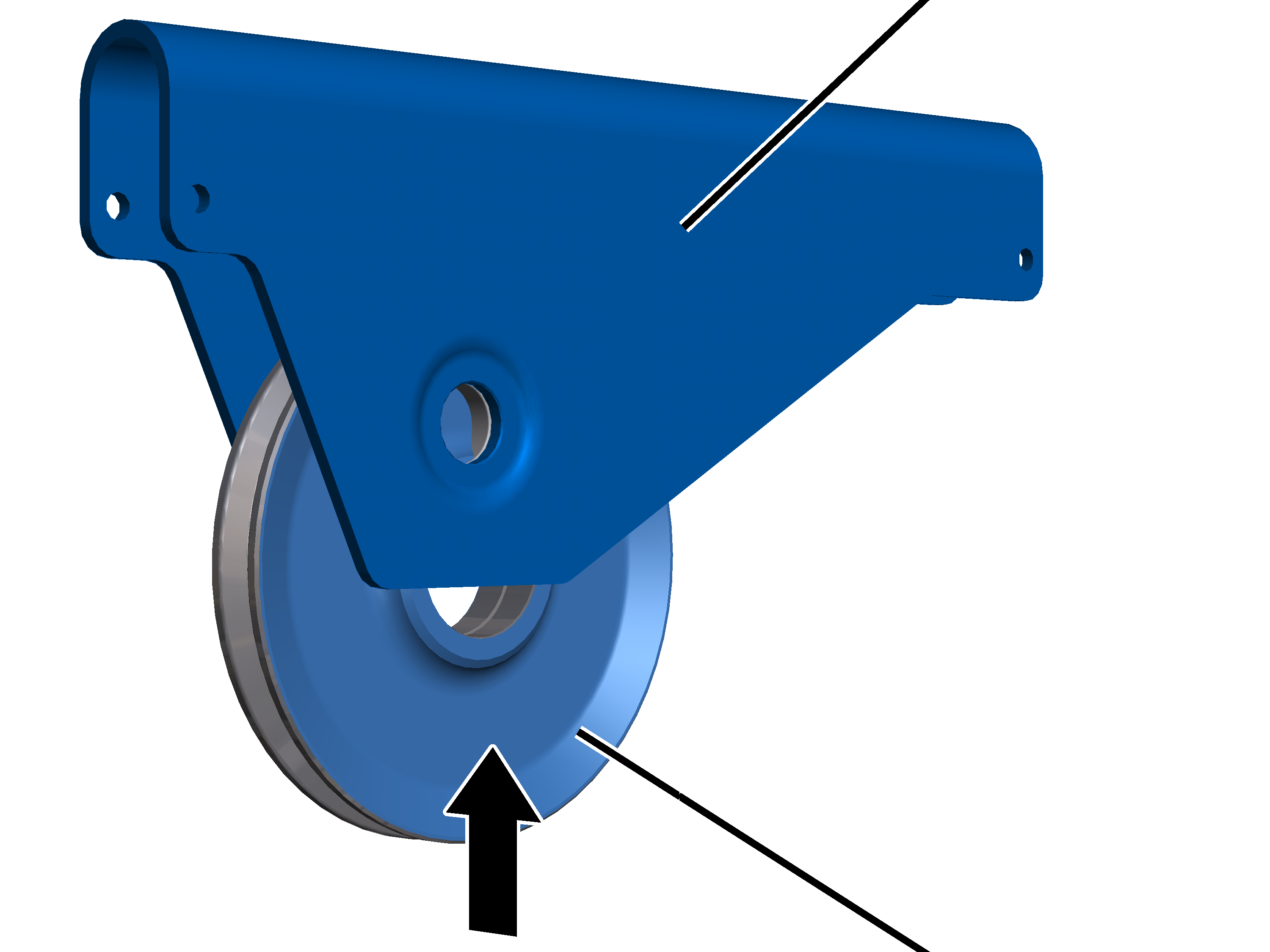
- Push the deflection roller into the deflection roller crosshead.
BoltDeflection roller crosshead
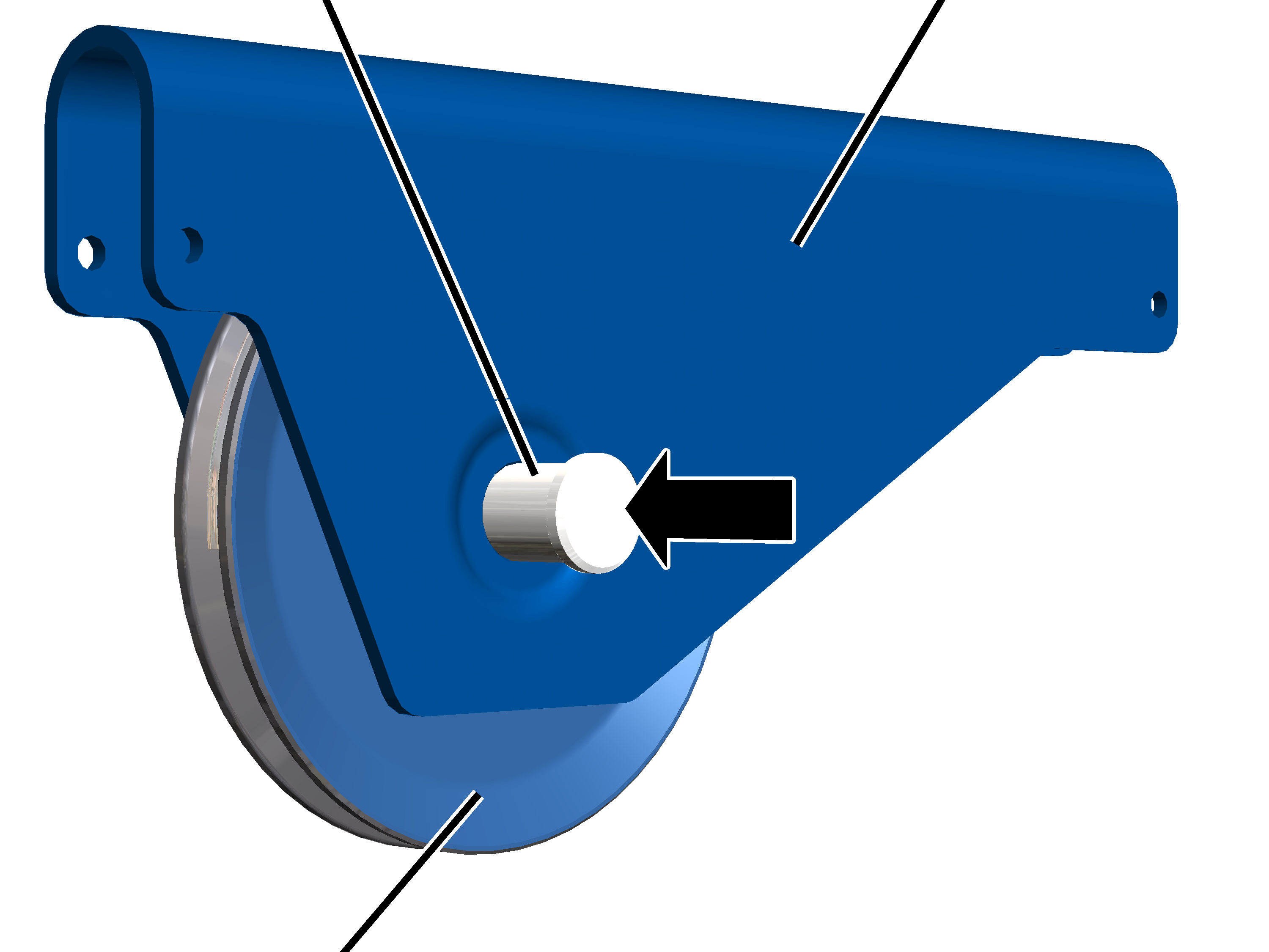
- Push the bolt through the deflection roller crosshead and deflection roller.
CoverRib screw
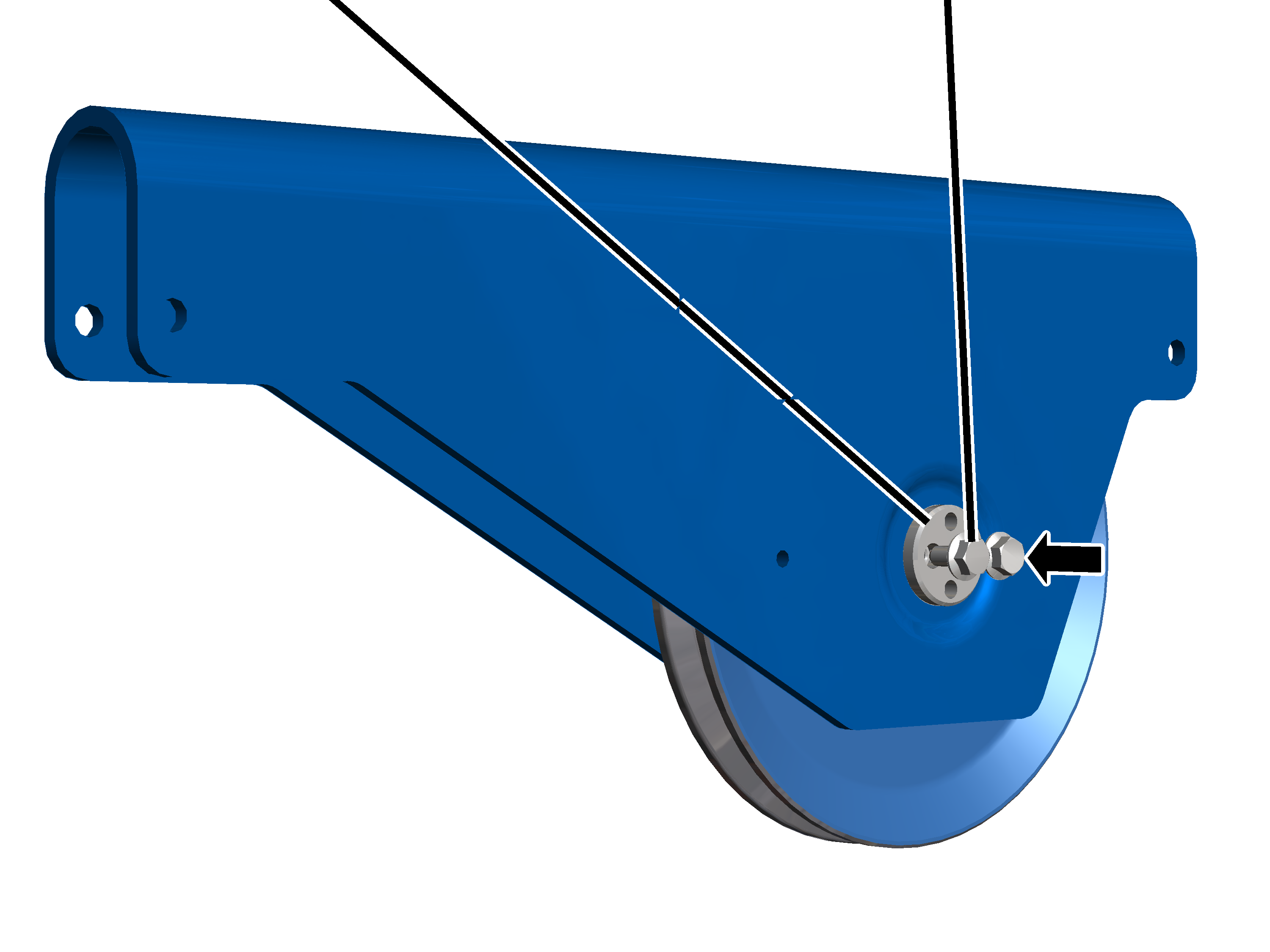
- Screw on the cover from the other side at the bolt with rib screws (2x).
Size |
Rib screw |
Tightening torque |
|---|---|---|
GM 800 |
M6x12 |
19 Nm |
GM 1000 |
M6x12 |
19 Nm |
GM 2000 |
M8x16 |
42 Nm |
GM 3000 |
M10x20 |
75 Nm |
Mounting the deflection roller crosshead
Deflection roller crosshead
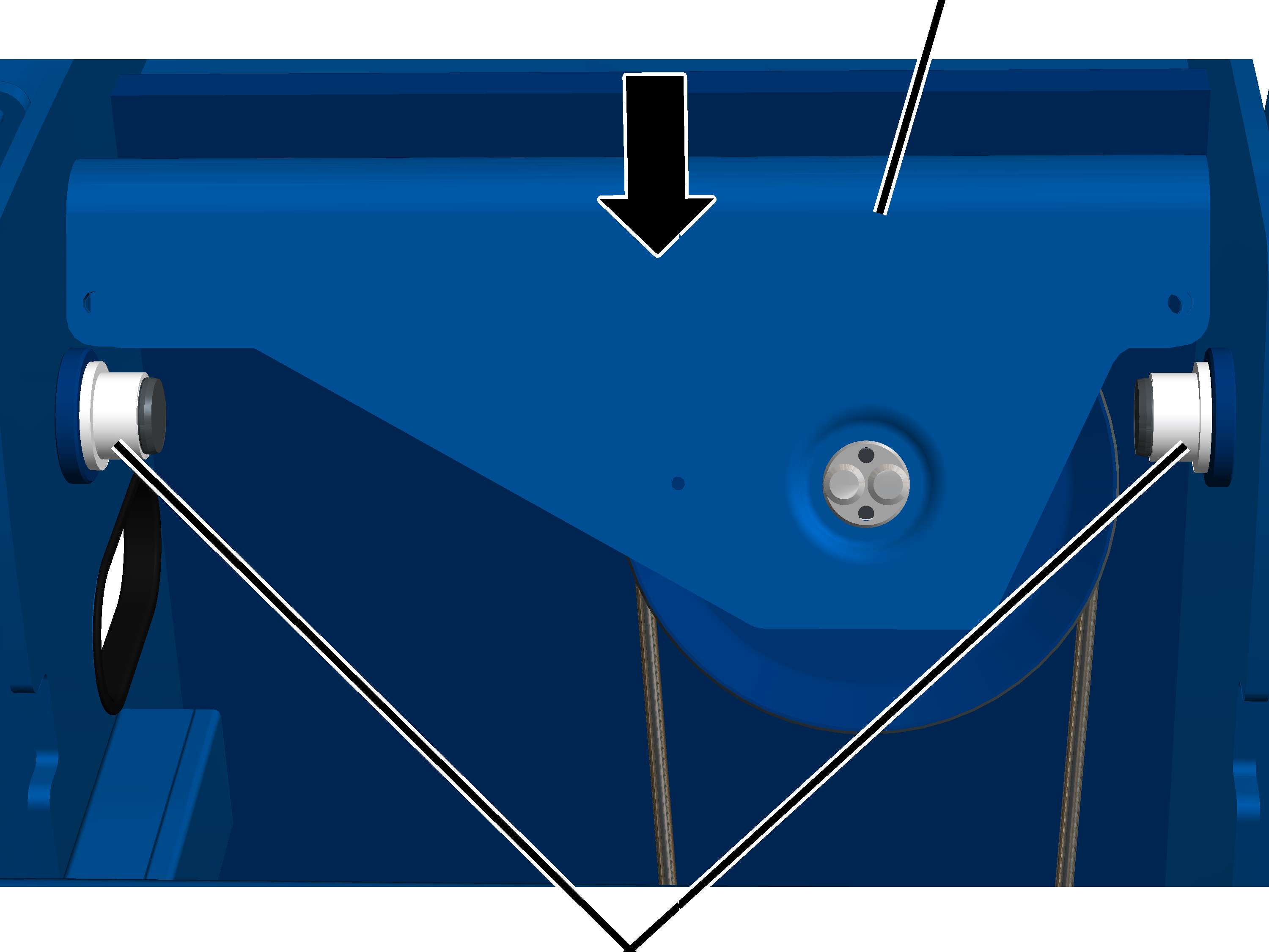
- Mount the deflection roller crosshead on the bearing bushes.
When doing this, ensure that the deflection roller points in the direction of the hoist drive.
Bolt
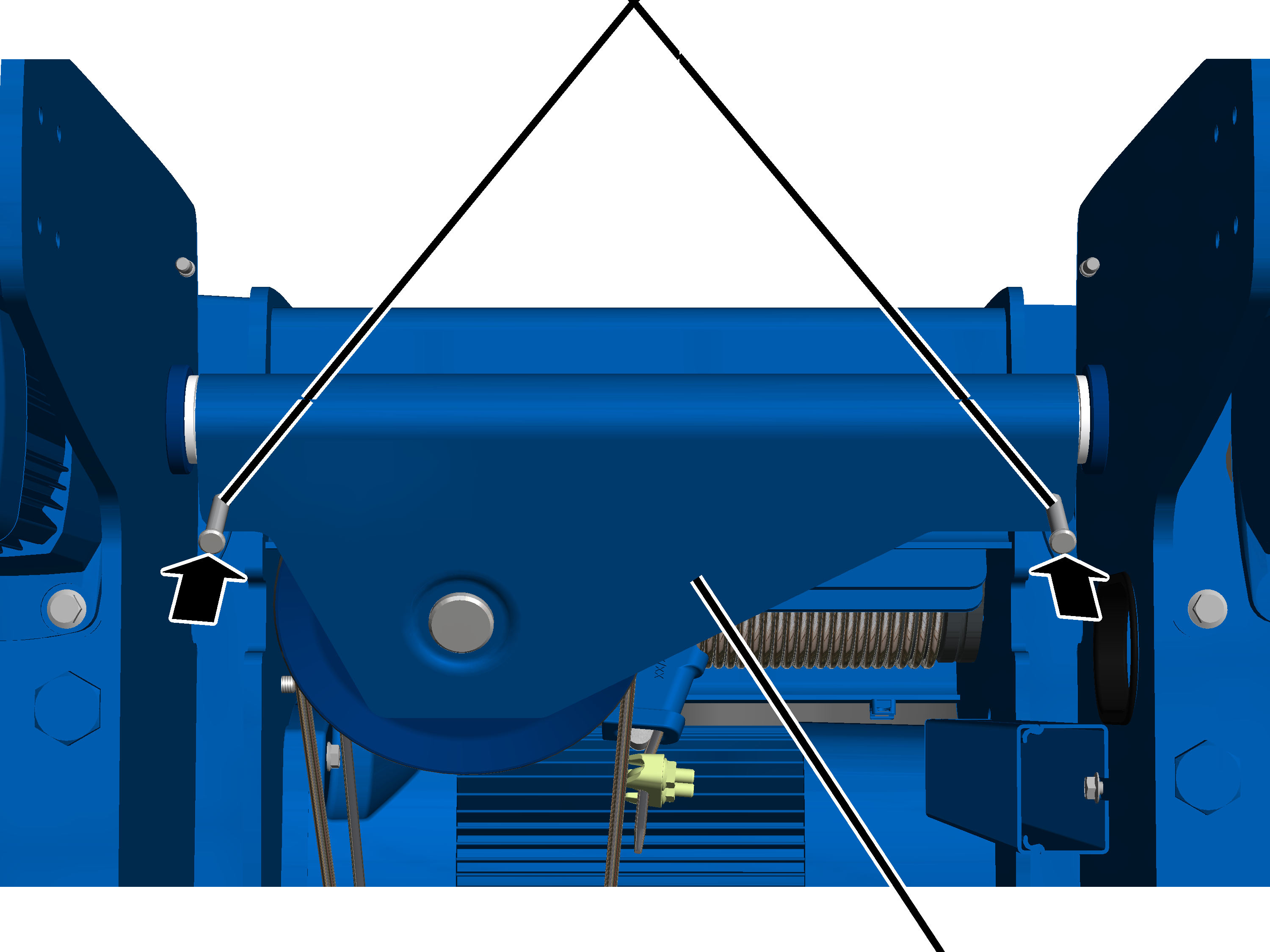
- Push the bolts (2x) into the deflection roller crosshead.
SL safety clip
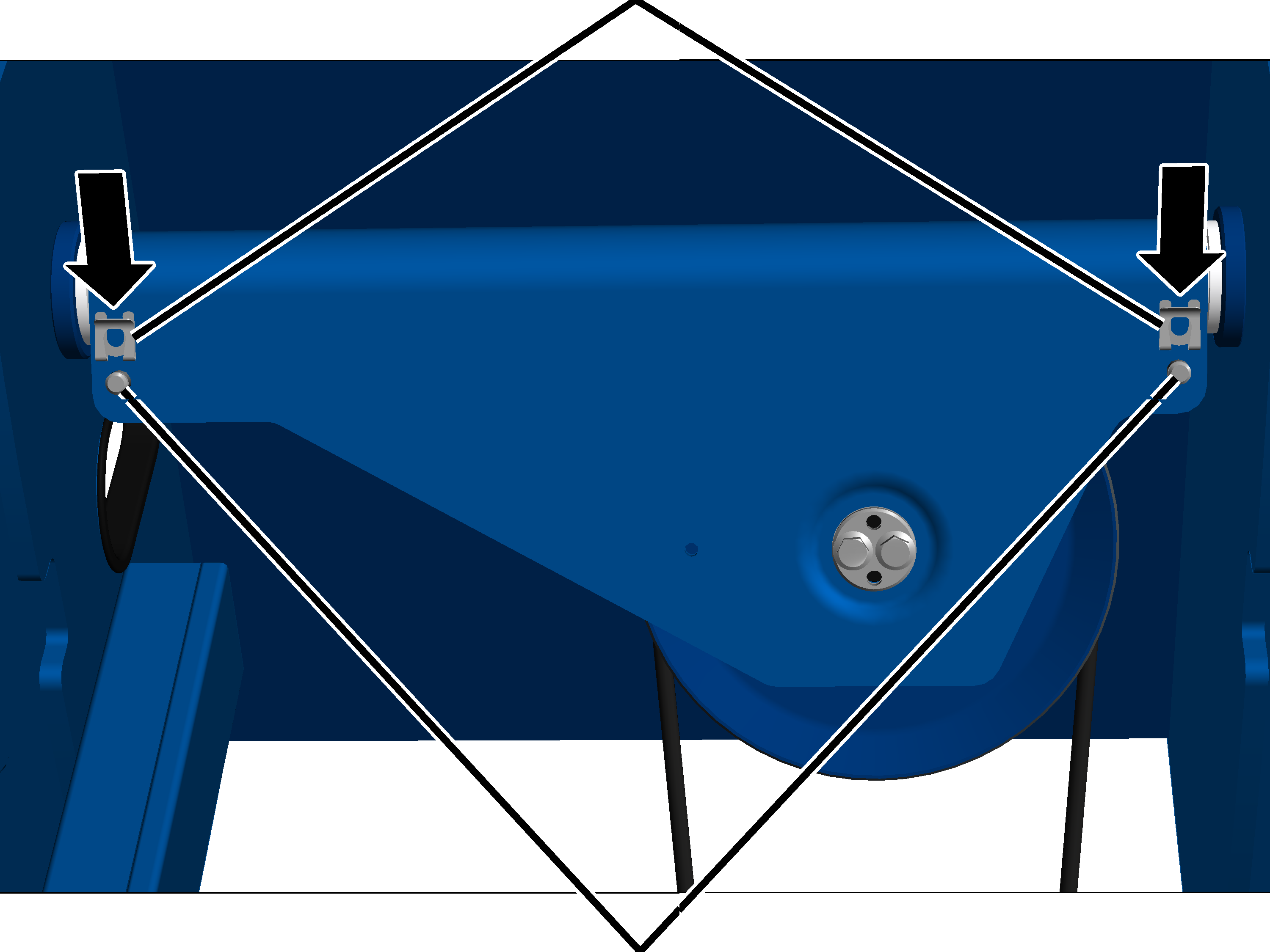
- Push the SL safety clips (2x) onto the bolts.
Disassembling the powered wheel
If the wheel is damaged or worn, it must be replaced with a new wheel.
Preparing the wire rope hoist
- Comply with occupational health and safety requirements.
- Relieve the load of the end carriage on the wire rope hoist near the wheel from below.
Removing the drive
Connector housing
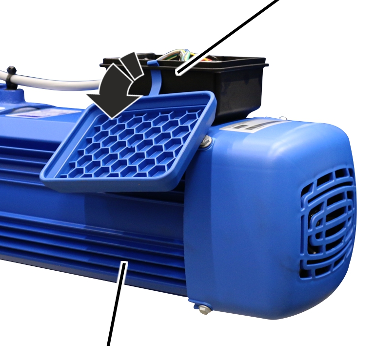
- Open the connector housing to the drive.
- Disconnect the connection cable from the coupler plug.
- Determine the weight of the drive. See the ABUS Drive product manual.
- Secure the drive so that the weight can be held safely and the output shaft will not be subject to load (e.g. insert in round sling).
Screws
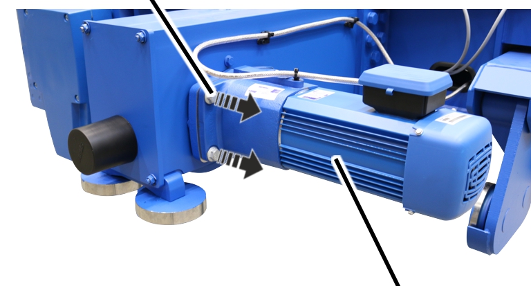
- Release the rib screws (4x).
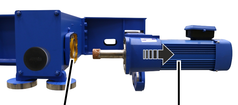
- Pull out the drive.
Exposing the wheel
Buffer plate
- Unscrew the self-locking nuts (4x).
- From size 160: remove the plastic washers (4x).
- Remove the buffer plate.
Clamping element
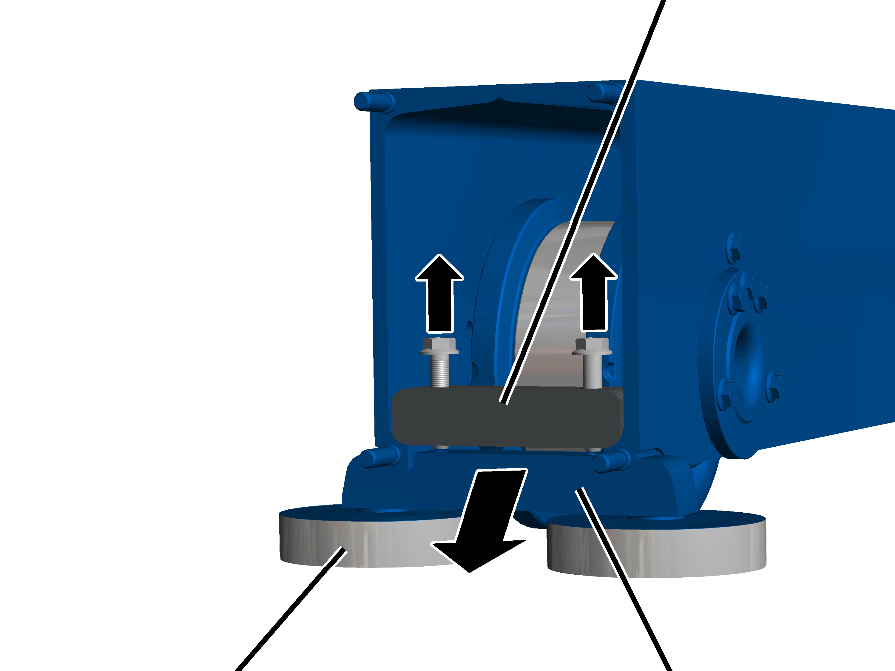
- Loosen screws (2x).
- Take out the bracket with guide rollers and clamping element.
Removing the wheel
Retaining screw
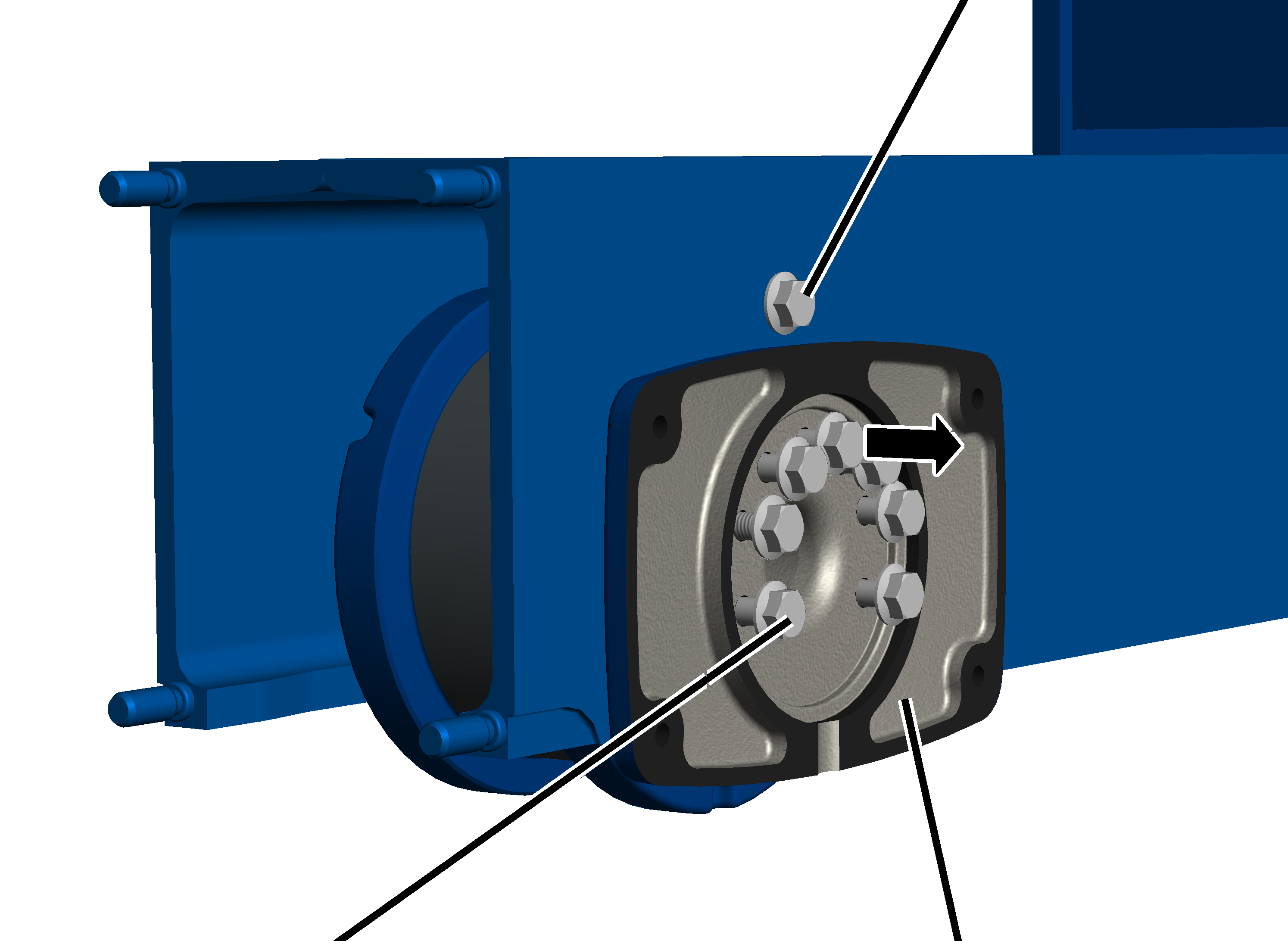
- Unscrew and remove all rib screws on the bearing flange. Do not unscrew and remove the retaining screw(s).
Retaining screw
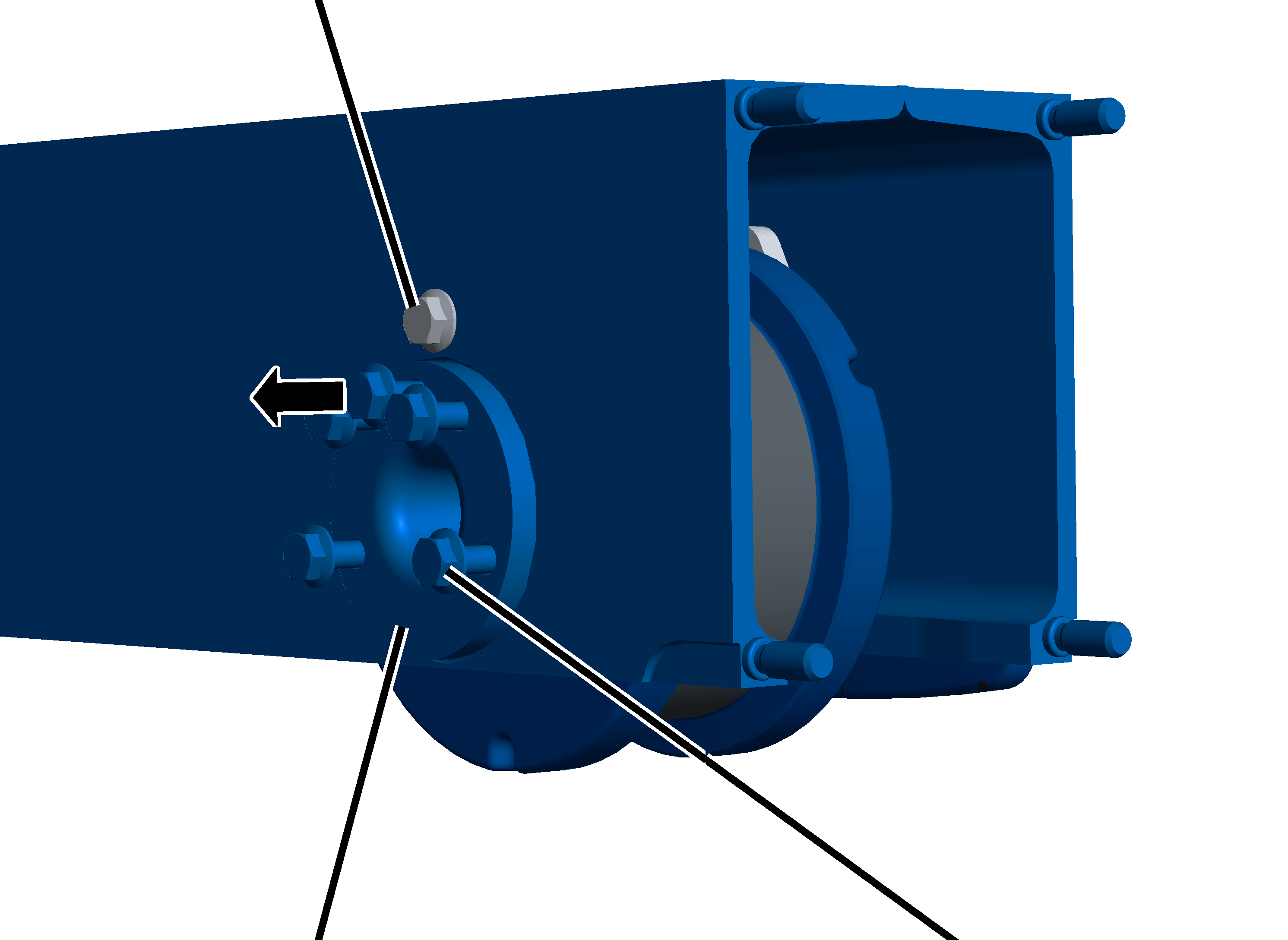
- Unscrew and remove all rib screws on the bearing bolt. Do not unscrew and remove the retaining screw(s).
Wheel
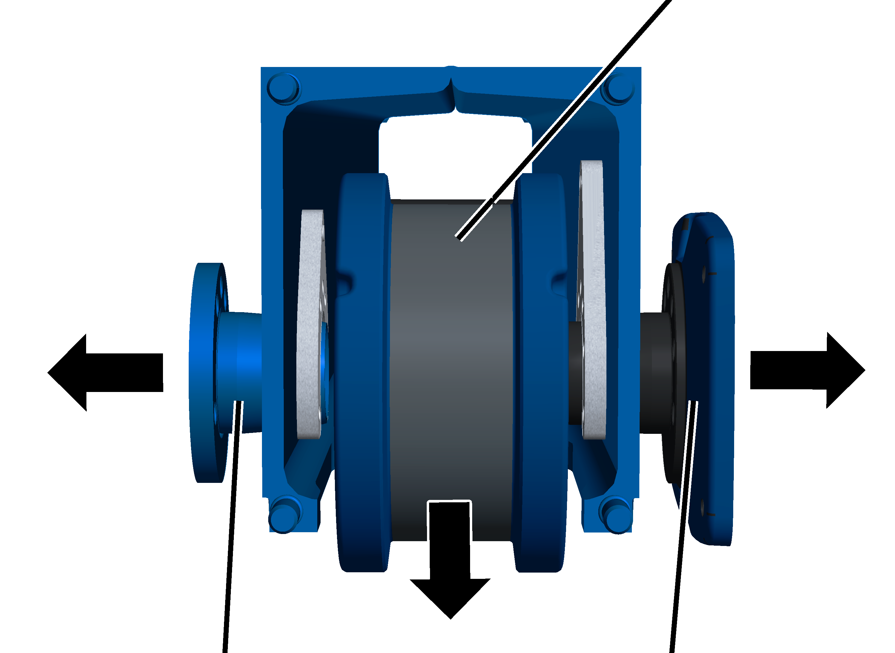
- Take out the bearing bolt, bearing flange and wheel.
Tip:
To be able to easily remove the bearing flange from the end carriage, screw two or four screws in the corners of the bearing flange, using them to press the bearing flange off the end carriage.
Installing the powered wheel
If the wheel is damaged or worn, it must be replaced with a new wheel.
Fitting the wheel
Wheel
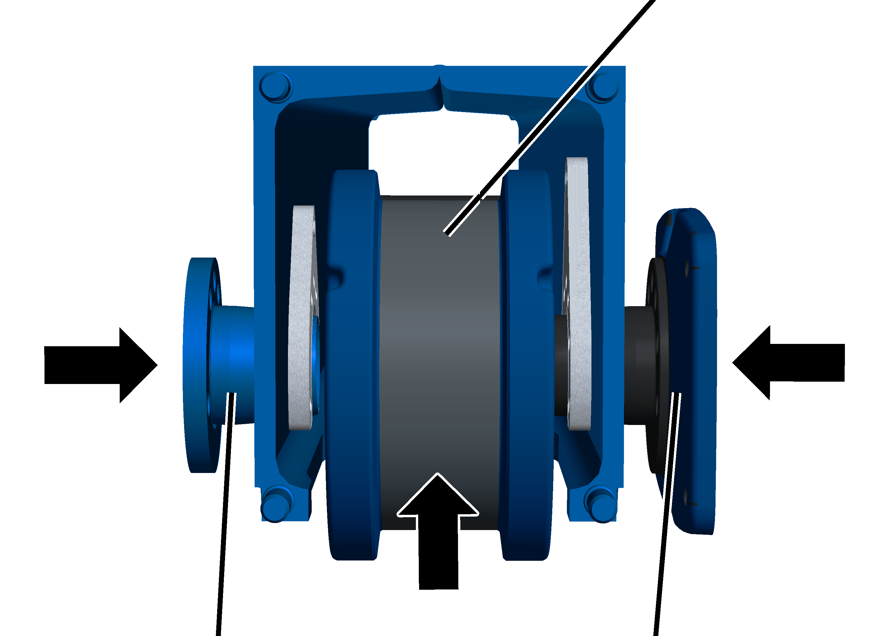
- Hold the wheel in the end carriage. It does not matter which side faces inwards or outwards.
- Insert the bearing bolt and bearing flange. If necessary, lightly hammer the bearing bolt and bearing flange.
Retaining screw
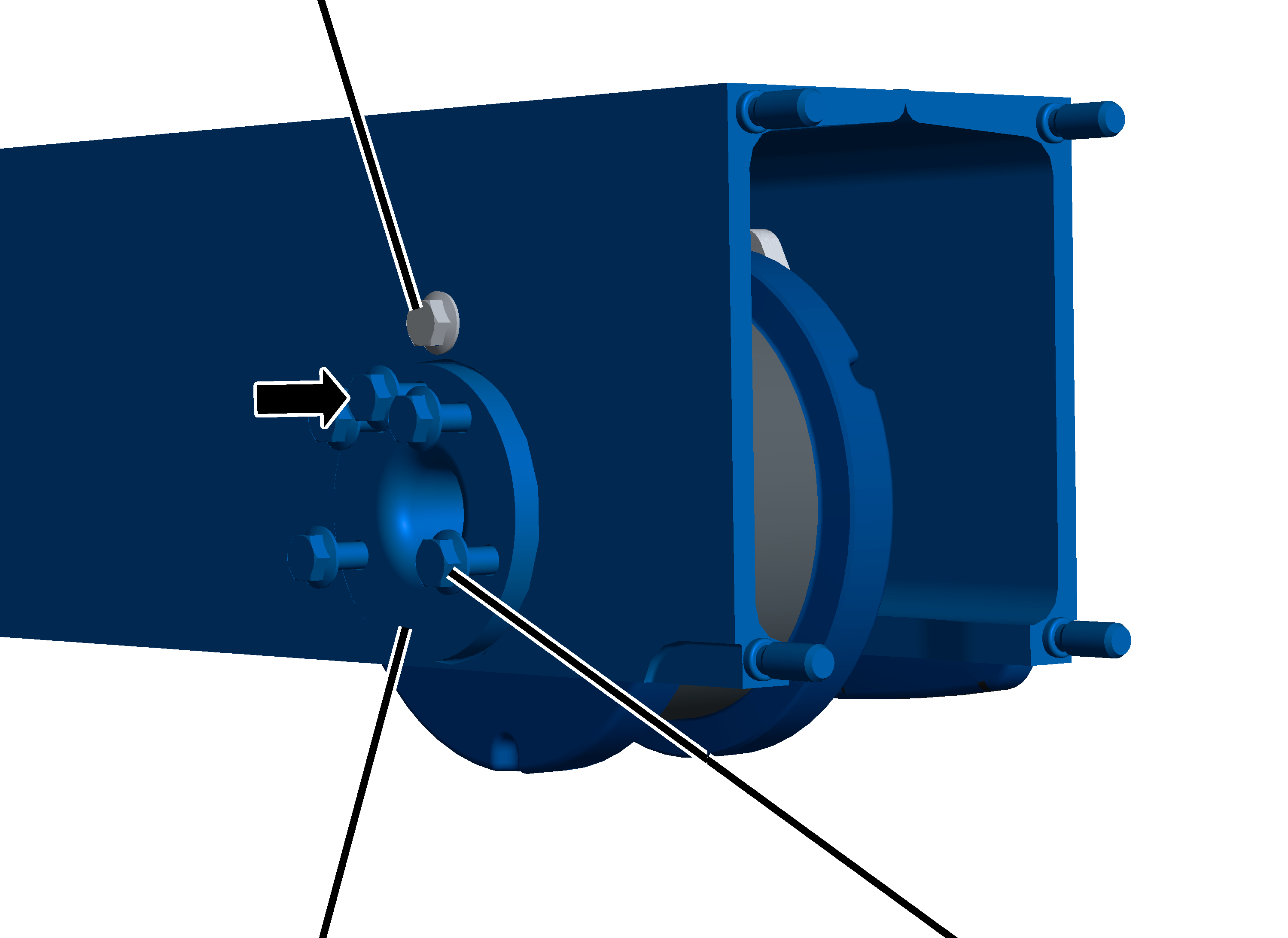
- Tighten the rib screws in stages.
Wheel Ø |
Strength category |
Number |
Screw |
Tightening torque |
|---|---|---|---|---|
160 |
10.9 |
5x |
M8x25 |
42 Nm |
200 |
10.9 |
5x |
M10x30 |
85 Nm |
280 |
10.9 |
5x |
M12x40 |
130 Nm |
Fastening the bearing flange
Retaining screw
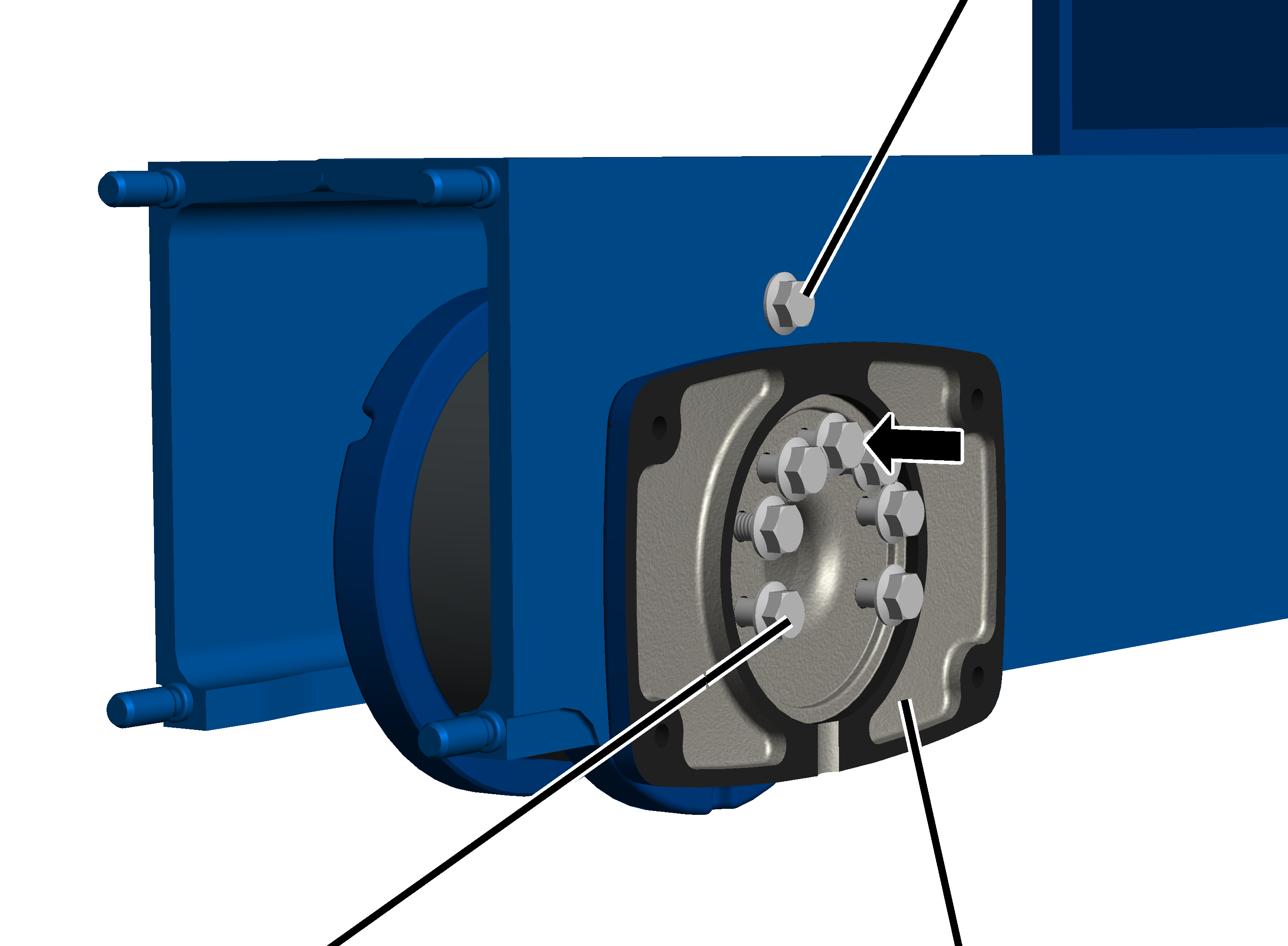
- Tighten the rib screws in stages.
Wheel Ø |
Strength category |
Number |
Rib screws |
Tightening torque |
|---|---|---|---|---|
160 |
10.9 |
7x |
M8x25 |
42 Nm |
200 |
10.9 |
7x |
M10x30 |
85 Nm |
280 |
10.9 |
7x |
M12x40 |
130 Nm |
Assembling the end carriage
Clamping element
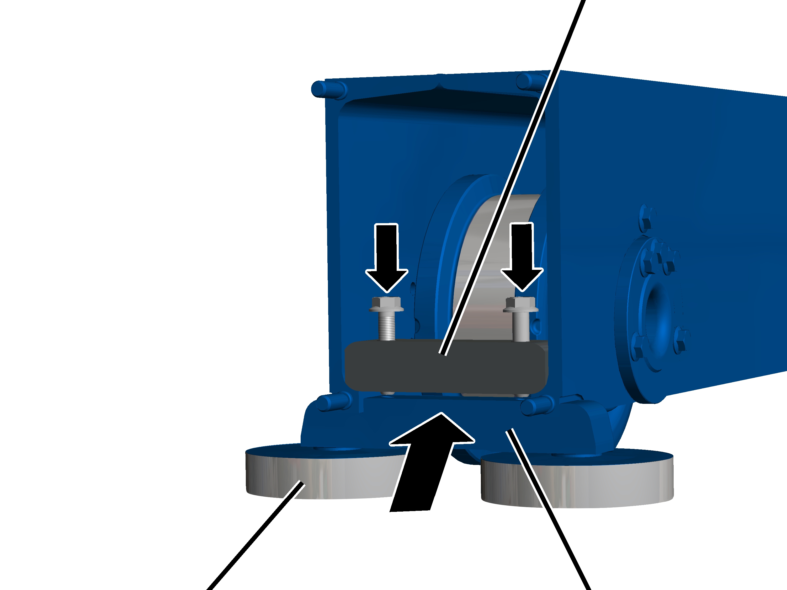
- Insert the bracket with guide rollers and clamping element.
- Tighten screws (2x).
Wheel Ø |
Rib screw |
Tightening torque |
|---|---|---|
160 |
M10x50 |
85 Nm |
200 |
M10x50 |
85 Nm |
280 |
M12x60 |
130 Nm |
Buffer plate
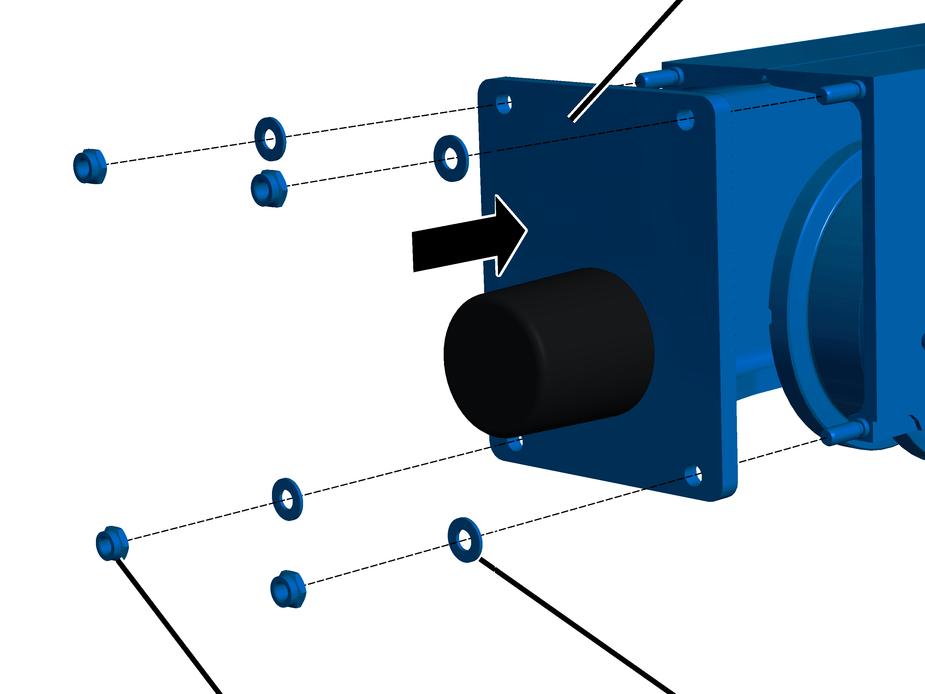
- Slide the buffer plate onto the threaded bolt.
- From size 160: fit the plastic washers (4x) in place.
- Tightly screw the self-locking nuts M10 (4x). 6 Nm
The self-locking nuts may only be reused a maximum of 3 times. After this, new self-locking nuts must be used.
Installing the drive
- Determine the weight of the drive. See the ABUS Drive product manual.
- Secure the drive so that the weight can be held safely and the output shaft will not be subject to load (e.g. insert in round sling).
Output shaft
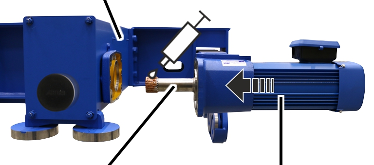
- Lubricate the gearing on the output shaft. Apply lubricant with brush to coat surface completely.
Lubricant: “High temperature paste PBC 1574”. See the ABUS Drive product manual for details.
Rib screw
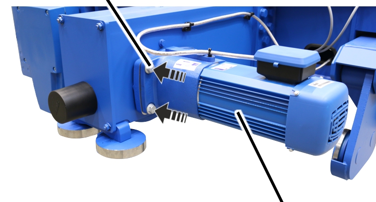
- Push the drive into the wheel.
- Bolt on the drive with the rib screws (4x).
Wheel Ø |
Rib screw |
Tightening torque |
|---|---|---|
160 |
M10x30 |
75 Nm |
200 |
M12x30 |
115 Nm |
280 |
M16x40 |
300 Nm |
Connecting the drive
Only with contactor control
Pin multipoint connector on the drivePin multipoint connector on the drive
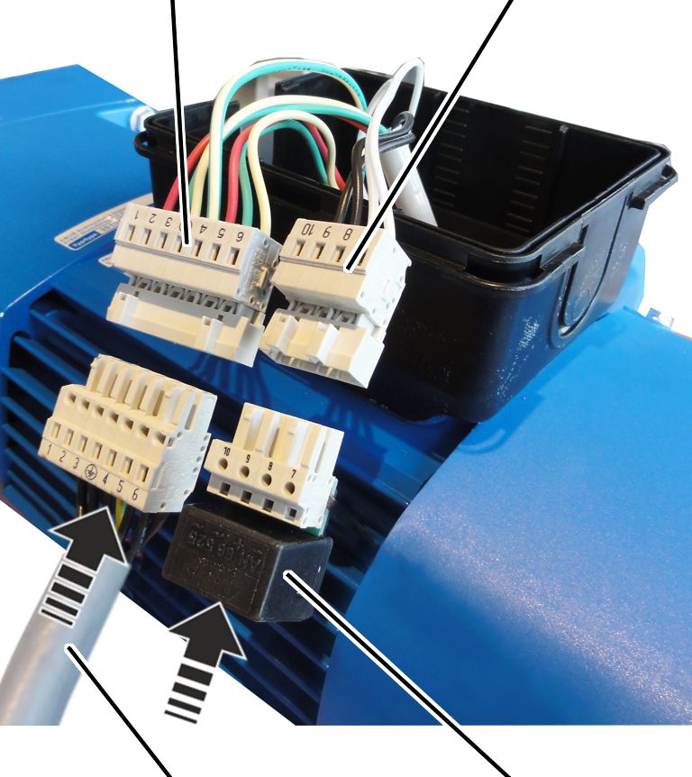
- Insert the connection cable for the drive in the pin multipoint connector on the drive.
- Insert the rectifier for the brake in the pin multipoint connector on the drive.
- Lay the plug-in connections and connection cable in the connector housing.
Only for frequency converter
Pin multipoint connector on the drivePin multipoint connector on the drive
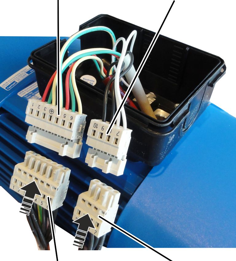
- Insert the bush multipoint connector for the drive on the pin multipoint connector on the drive.
- Insert the bush multipoint connector for the brake on the pin multipoint connector on the drive.
Plug-in connectionCable bushing
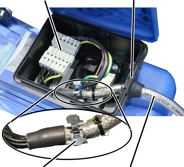
- Push the front end of the connection cable (where the sheathing around the shield has been removed) into the screening clamp connection.
- Fasten the connection cable to the screening clamp connection using cable ties.
- Lay the plug-in connections and connection cable in the connector housing.
- Close the housing cover.
Checking the wire rope hoist
- Set the wire rope hoist down again.
- Put the wire rope hoist into operation.
- Check the function of the wheel.
Disassembling the non-powered wheel
If the wheel is damaged or worn, it must be replaced with a new wheel.
Preparing the wire rope hoist
- Comply with occupational health and safety requirements.
- Relieve the load of the end carriage on the wire rope hoist near the wheel from below.
Exposing the wheel
Buffer plate
- Unscrew the self-locking nuts (4x).
- From size 160: remove the plastic washers (4x).
- Remove the buffer plate.
Clamping element
- Loosen screws (2x).
- Take out the bracket with guide rollers and clamping element.
Removing the wheel
On both sides:
Retaining screw
- Unscrew and remove all rib screws on the bearing bolt. Do not unscrew and remove the retaining screw(s).
Wheel
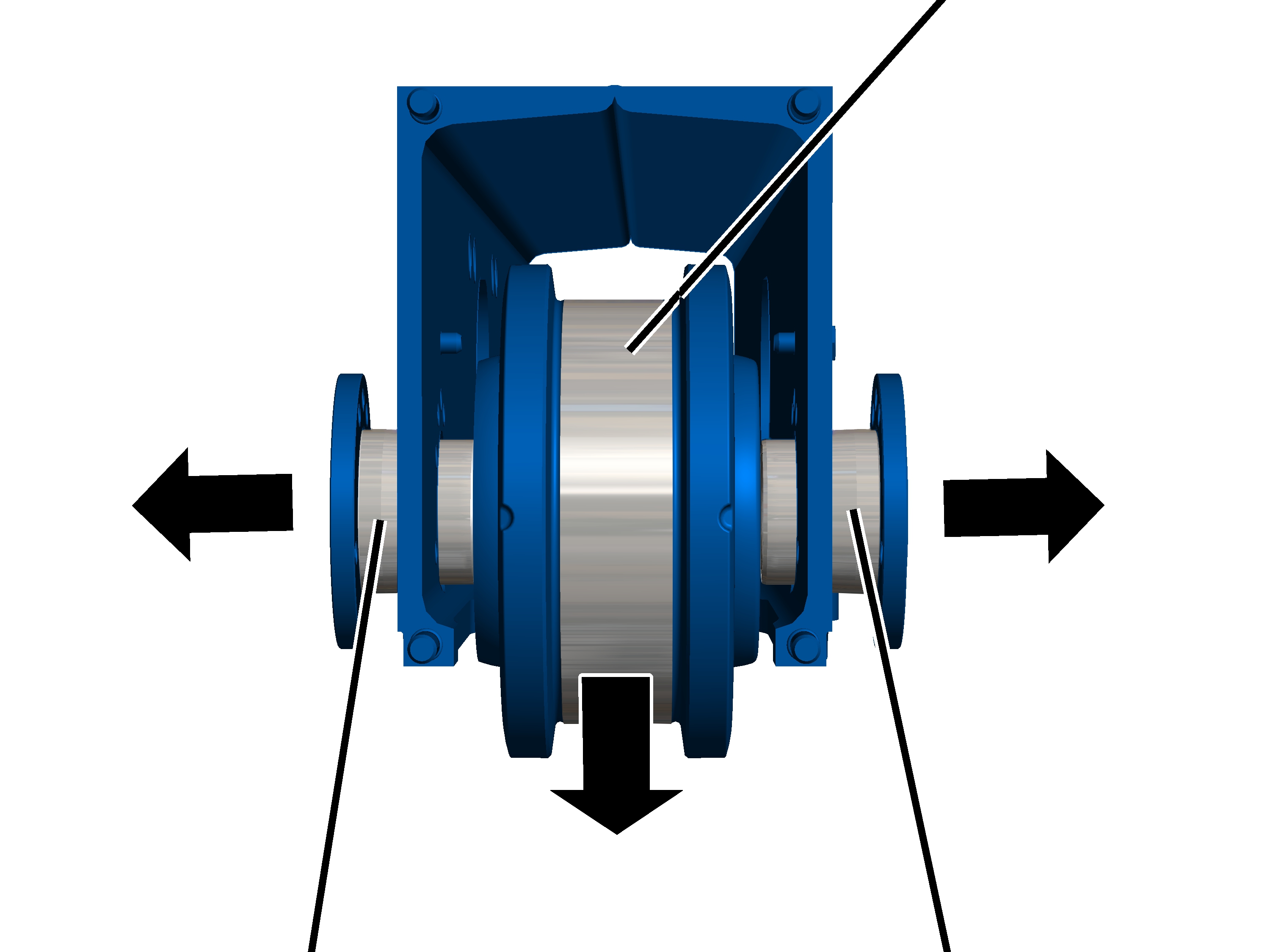
- Take out the bearing bolt.
Installing the non-powered wheel
If the wheel is damaged or worn, it must be replaced with a new wheel.
Fitting the wheel
Wheel
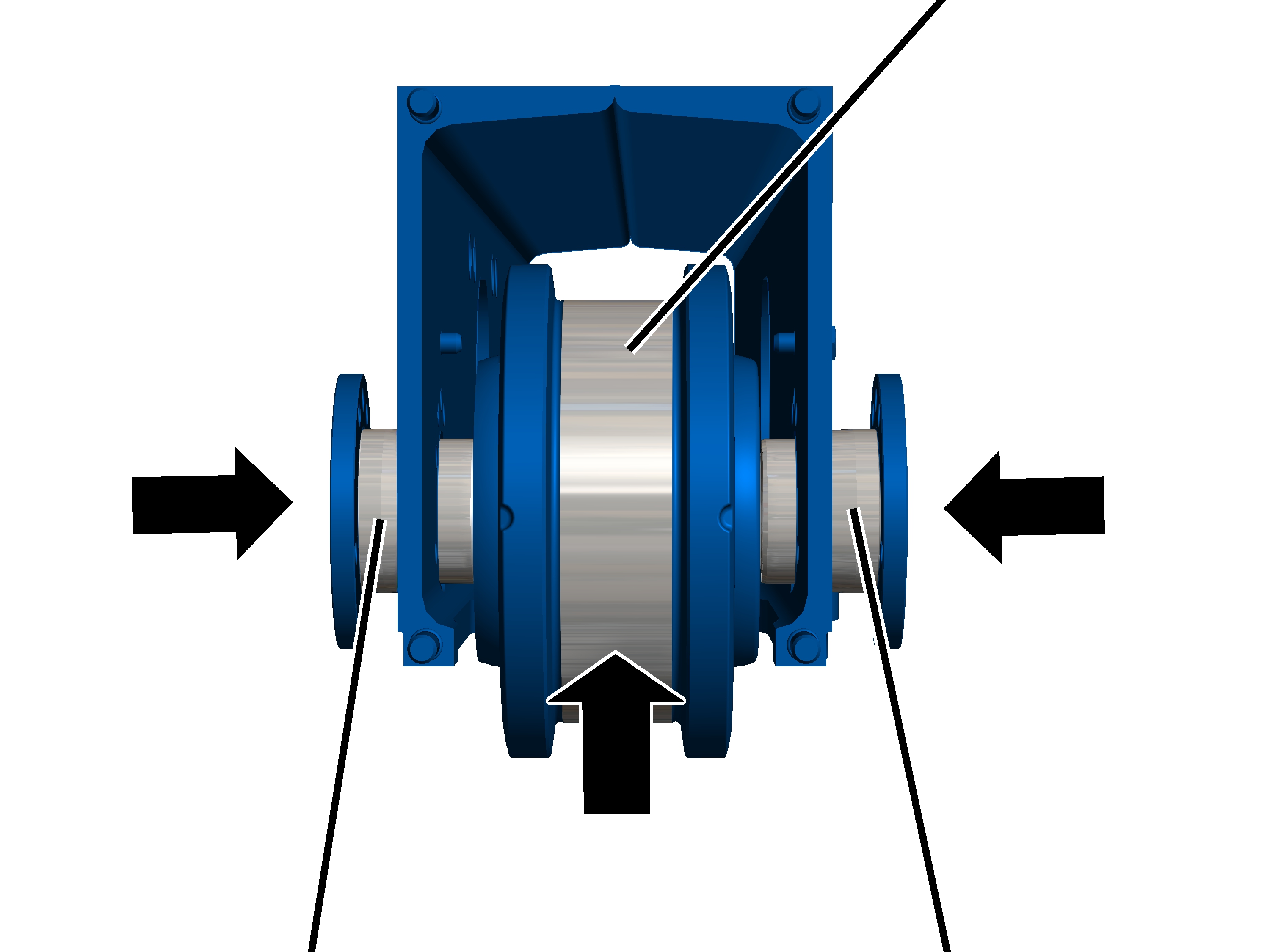
- Hold the wheel in the end carriage. It does not matter which side faces inwards or outwards.
- Insert the bolt and distance bush. If necessary, lightly hammer the bolt and distance bush.
Retaining screw
- Tighten the rib screws in stages.
Wheel Ø |
Strength category |
Number |
Rib screws |
Tightening torque |
|---|---|---|---|---|
160 |
10.9 |
5x |
M8x25 |
42 Nm |
200 |
10.9 |
5x |
M10x30 |
85 Nm |
280 |
10.9 |
5x |
M12x40 |
130 Nm |
Clamping element
- Insert the bracket with guide rollers and clamping element.
- Tighten screws (2x).
Wheel Ø |
Rib screw |
Tightening torque |
|---|---|---|
160 |
M10x50 |
85 Nm |
200 |
M10x50 |
85 Nm |
280 |
M12x60 |
130 Nm |
Buffer plate
- Slide the buffer plate onto the threaded bolt.
- From size 160: fit the plastic washers (4x) in place.
- Tightly screw the self-locking nuts M10 (4x). 6 Nm
The self-locking nuts may only be reused a maximum of 3 times. After this, new self-locking nuts must be used.
Checking the wire rope hoist
- Set the wire rope hoist down again.
- Put the wire rope hoist into operation.
- Check the function of the wheel.
Replacing the supporting wheels
If the supporting wheels are damaged or worn, they must be replaced by new supporting wheels.
Removing the side frame
- Secure the wire rope hoist against falling.
Only with size GM 800
With the size GM 800, the side frame is fastened directly on the bracket by the eccentric bolt.
Eccentric boltRib screw
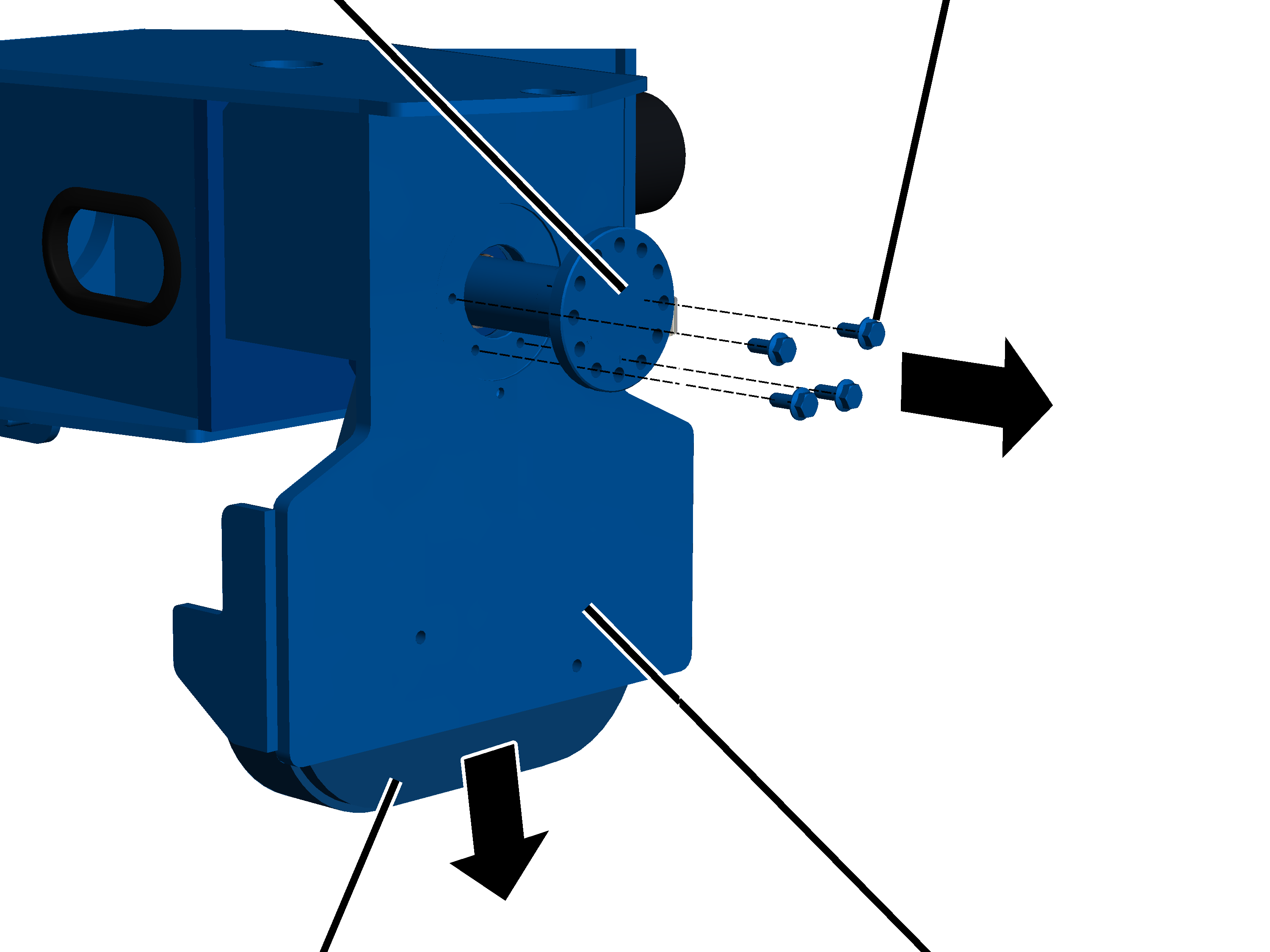
- Secure the side frame against falling.
- Release the rib screws on the eccentric bolt.
- Pull the eccentric bolt out of the mount and pull the side frame out downwardly.
Only with the size GM 1000 to GM 3000
With the size GM 1000 to GM 3000, two side frames are fastened on a rocker on the bracket by the eccentric bolt.
- Fix the rocker in position, e.g. with a wedge.
On both sides of the rocker:
Rib screwCover
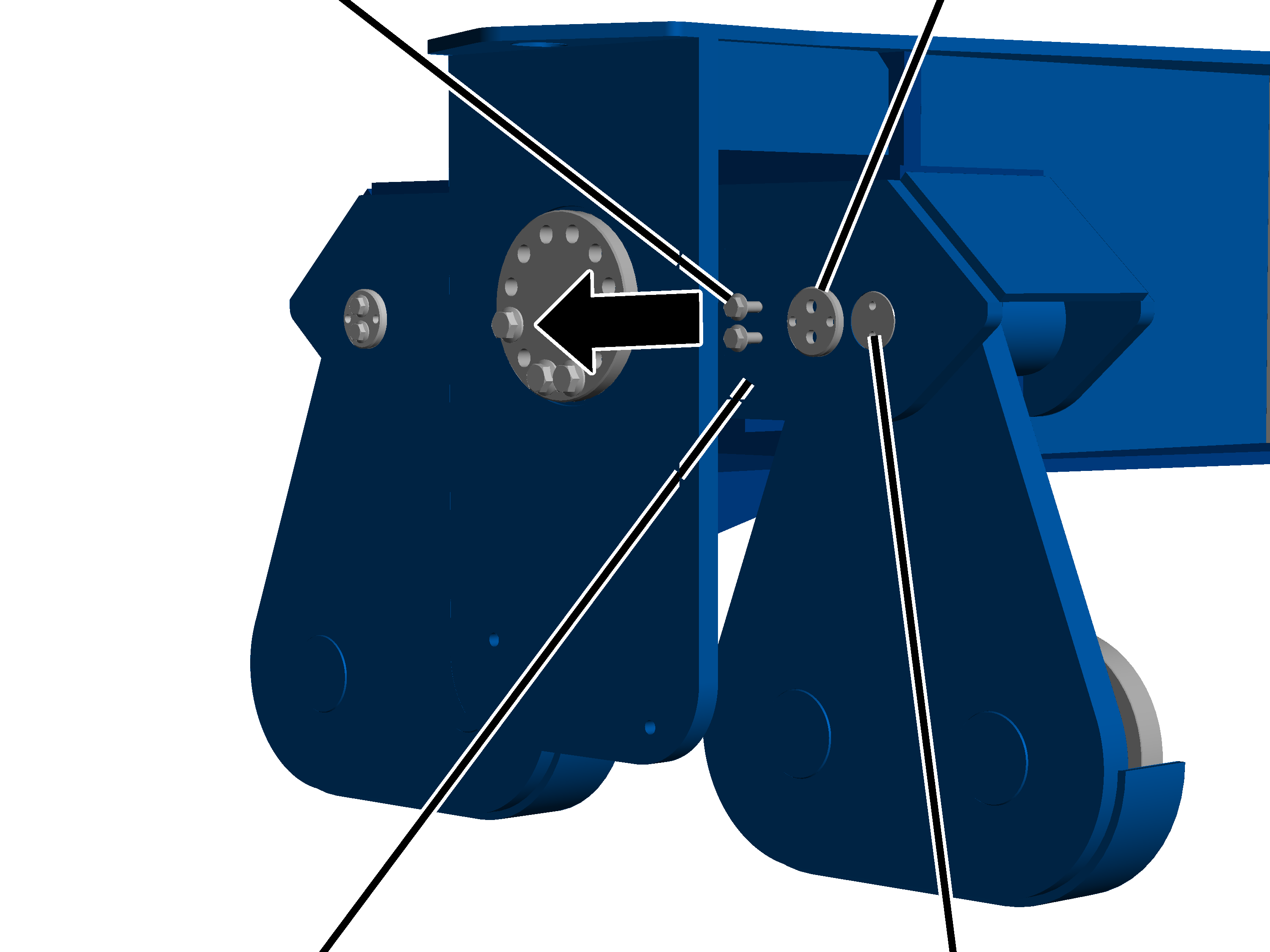
- Secure the side frame against falling.
- Release the rib screws on the cover.
- Take off the cover.
Rocker
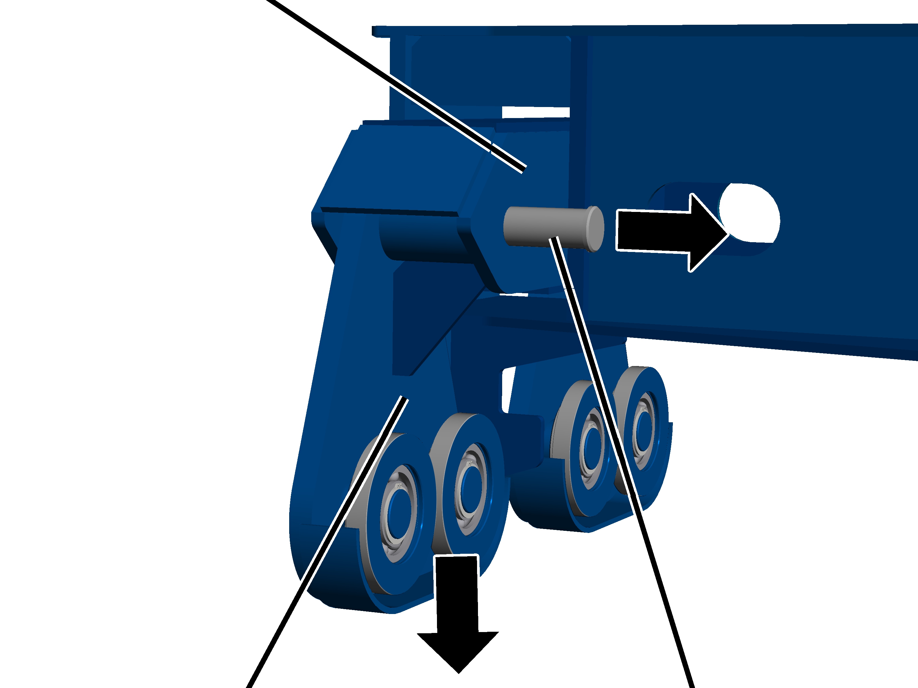
- Pull the bolt out of the rocker and the side frame.
- Pull the side frame out downwards.
Disassembling the supporting wheels
Circlip
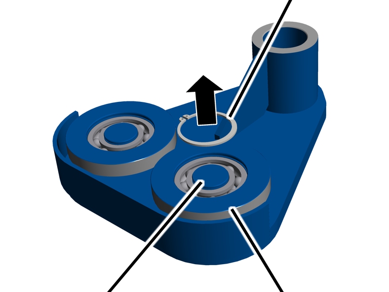
- Lay the side frame on an even surface with the supporting wheels facing upward.
- Remove the circlips (2x) from the bolt in the interior of the supporting wheels (2x).
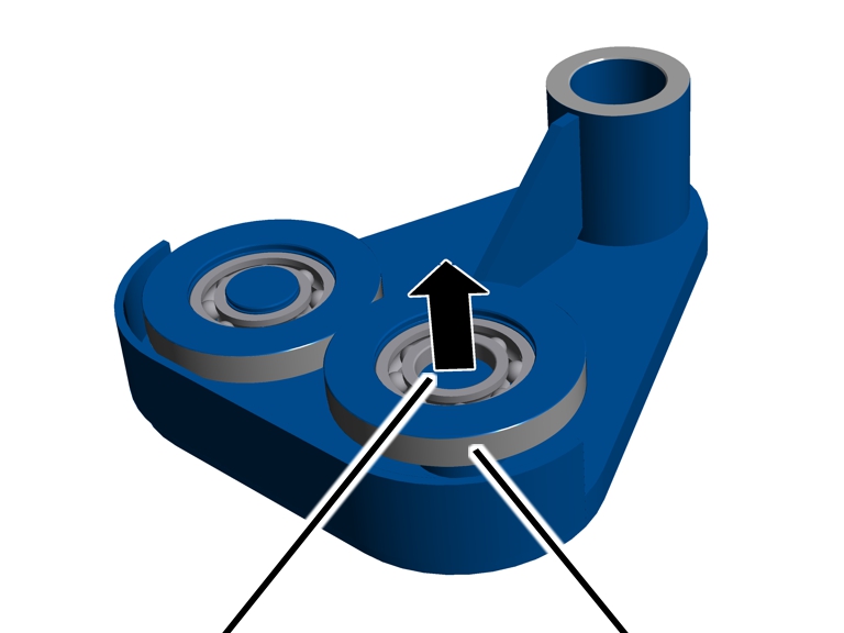
- Remove the supporting wheels (2x) from the bolt with a suitable tool.
Assembling the supporting wheels
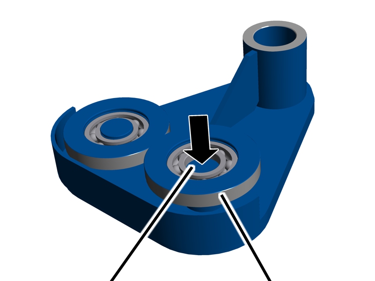
- Hammer the supporting wheels (2x) onto the bolt.
Circlip
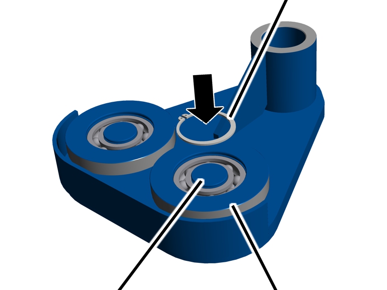
- Insert circlips (2x) on the bolt in the interior of the supporting wheels.
Fitting the side frame
Only with size GM 800
With the size GM 800, the side frame is fastened directly on the bracket by the eccentric bolt.
Eccentric boltRib screws
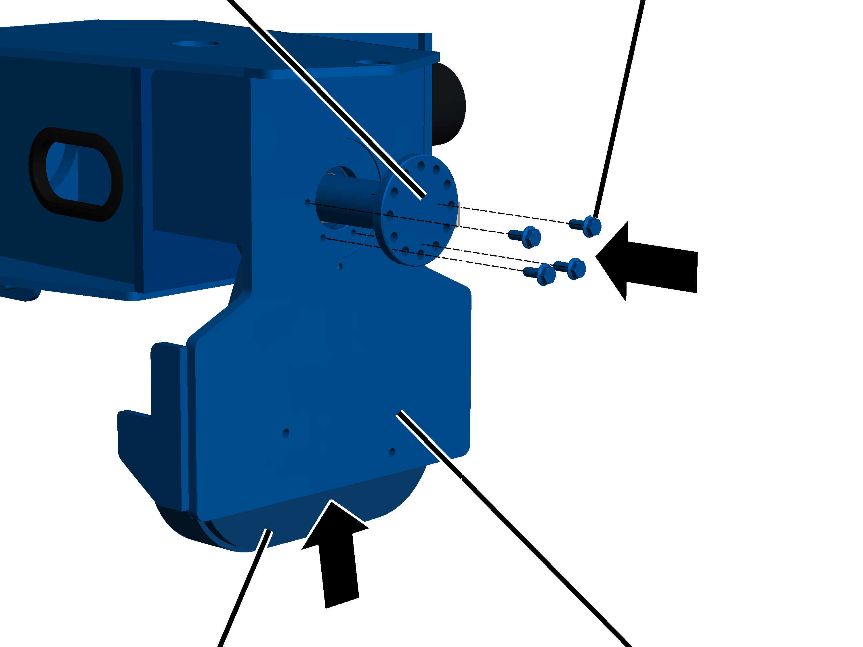
- Push the side frame into the bracket.
- Push the eccentric bolt through the bracket and the side frame.
- Tighten the rib screws M8x25 on the eccentric bolt. 42 Nm.
Only with the size GM 1000 to GM 3000
With the size GM 1000 to GM 3000, two side frames are fastened on a rocker on the bracket by the eccentric bolt.
On both sides of the rocker:
Rocker
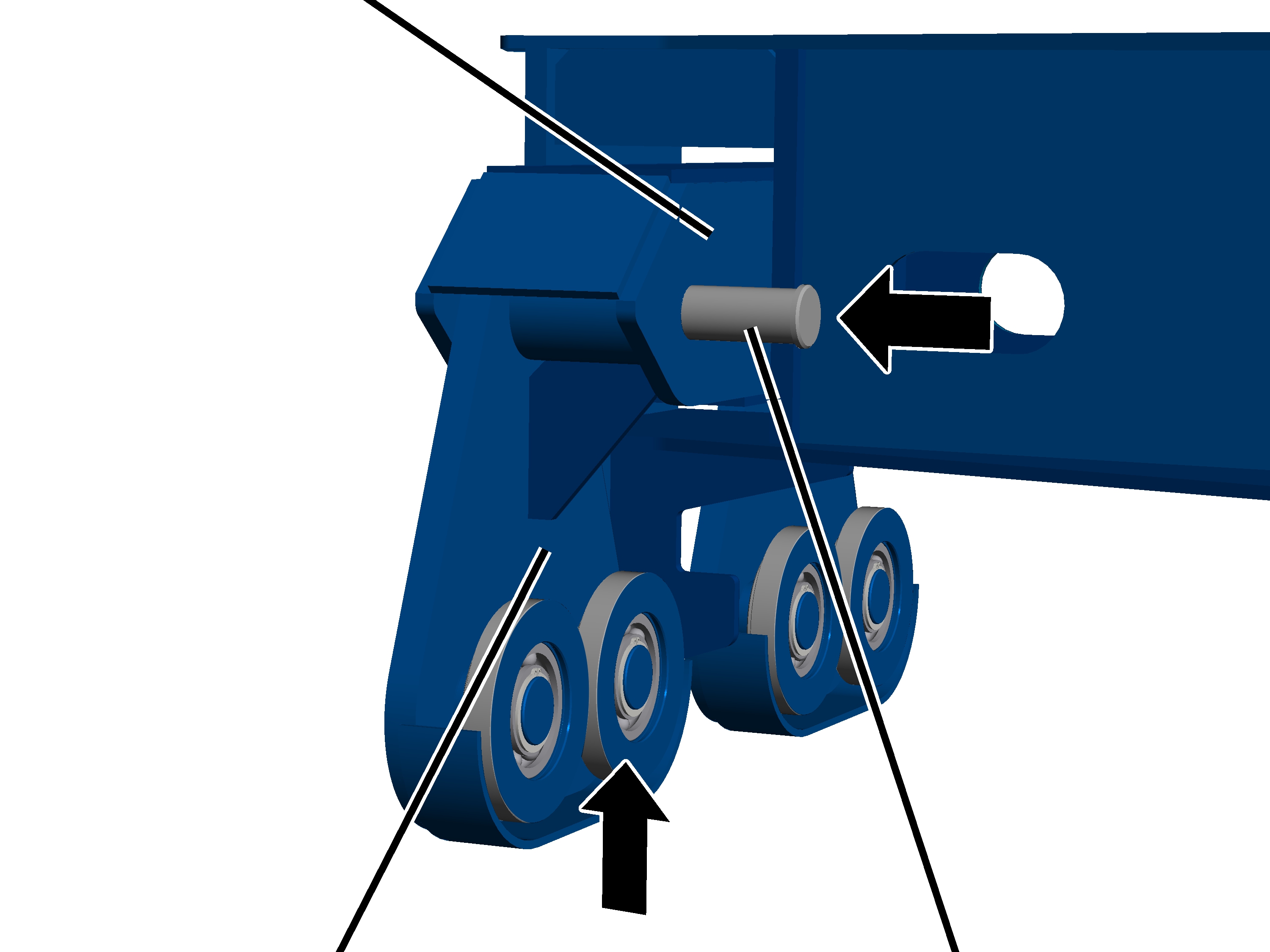
- Push the side frame into the rocker.
- Push the bolt through the rocker and the side frame.
Rib screwCover
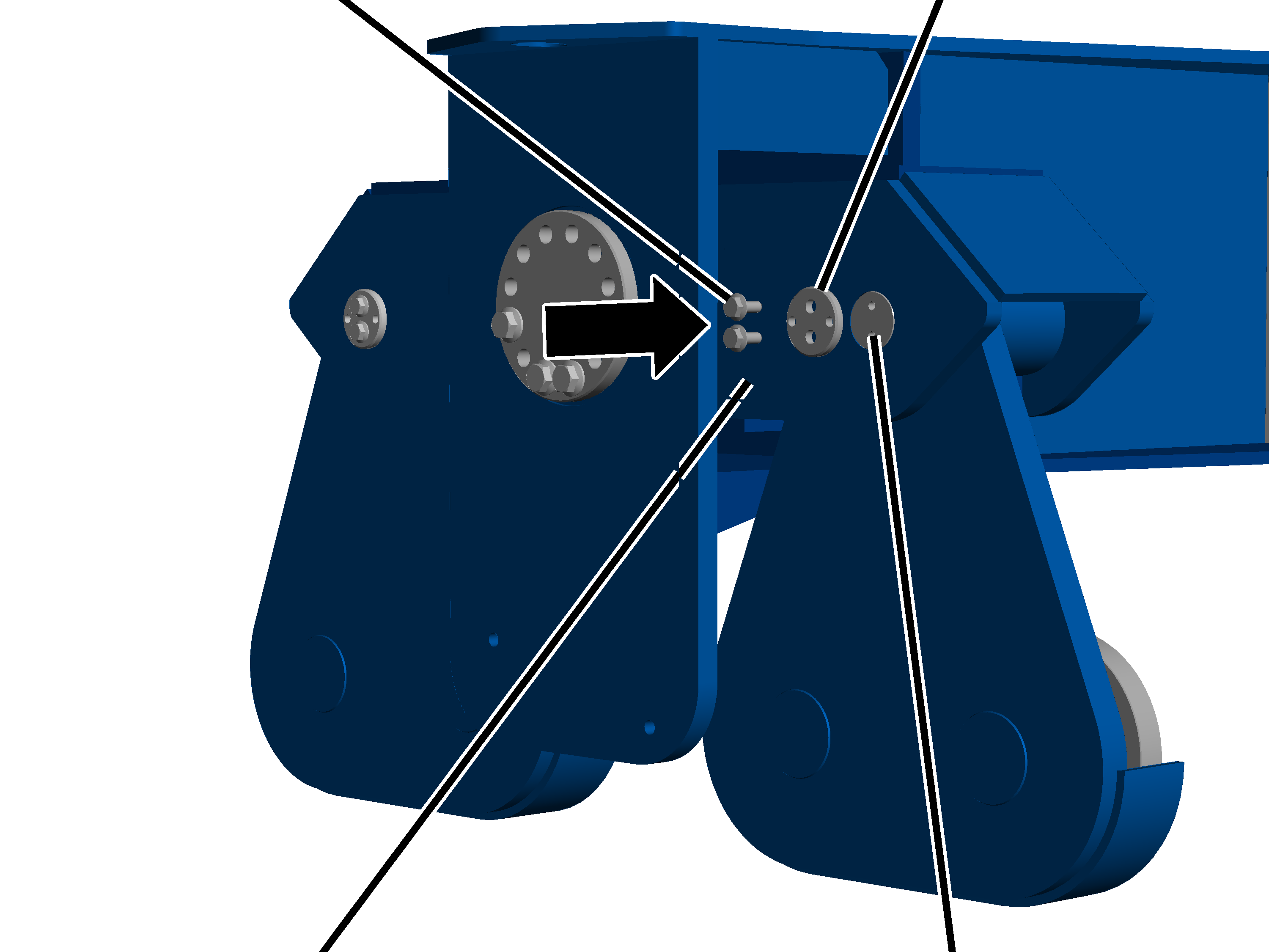
- Screw the cover tight with rib screws on the bolt.
Size |
Wheel Ø |
Rib screw |
Tightening torque |
|---|---|---|---|
GM 1000 |
200 |
M10x25 |
75 Nm |
GM 2000 |
200 |
M10x25 |
75 Nm |
GM 3000 |
200 |
M10x25 |
75 Nm |
GM 3000 |
280 |
M12x25 |
115 Nm |
- Remove the fixation of the rocker.
Replacing the safety buffer
If the safety buffer is damaged, it must be replaced.
On both sides:
Buffer plate
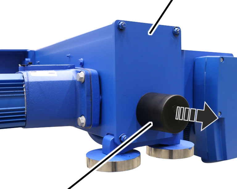
- Unscrew the safety buffer.
Buffer plate
- Screw safety buffers into the buffer plates. Approx. 30 Nm.
The safety buffer must be in contact with the buffer plate and there must be no gap between them, otherwise the impact will be absorbed by the screw and not by the safety buffer.
Replacing the cross-type limit switch
If the cross-type limit switch is damaged, it must be replaced. The plug-in connection allows you to carry out the replacement without any wiring work.
Coupling
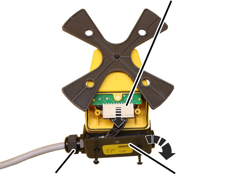
- Unscrew and remove the screws (2x) on the cover.
- Remove the cover.
- Disconnect the coupling of the connecting cable from the circuit board.
The cable fitting on the cover does not need to be unscrewed. The existing cover can be fitted with the attached connection cable to a new cross-type limit switch.
- Insert the coupling onto the new cross-type limit switch.
- Close the cover.
- Tighten screws (2x). 3 Nm.
Wiring diagram of the cross-type limit switch
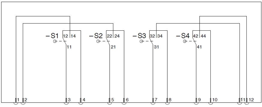
- The contact numbering shown on the wiring diagram starts on the left ascending from 1.
- The designation of the microswitches starts on the left of the installation position with S1.
Position arrow |
Switch position |
S1 closed |
S1 open |
S2 closed |
S2 open |
S3 closed |
S3 open |
S4 closed |
S4 open |
|---|---|---|---|---|---|---|---|---|---|
0 |
0° |
3.4 |
5.6 |
7.8 |
9.10 |
||||
1 |
90° |
3.4 |
5.6 |
7.11 |
9.10 |
||||
2 |
180° |
3.4 |
5.6 |
7.11 |
9.12 |
||||
3 |
270° |
3.1 |
5.6 |
7.8 |
9.12 |
||||
4 |
360° |
3.1 |
5.2 |
7.8 |
9.10 |
||||
5 |
450° |
3.4 |
5.2 |
7.8 |
9.10 |
||||
0 |
540° |
3.4 |
5.6 |
7.8 |
9.10 |
Lubricants
Note:
Synthetic lubricants must not be mixed with mineral-based lubricants!
Cable drum in the edge areas
On-site lubrication with “Molykote PG-75”, ABUS item number 5168.
Lubrication ex works with “Molykote PG-75”, ABUS item number 411.
Lubricate the wire rope during:
- Wire rope change
- Cable guide change
- Regular inspection
- General overhaul
For details, see “Cleaning and lubricating the cable drum”.
Wire rope and cable drum in the centre
On-site lubrication with “Chainlife S”, ABUS item number 2717
Lubrication ex works with “Chainlife S”, ABUS item number 2718.
Alternatives:
- Castrol “Viscogen KL 23”
- Klüber “Grafloscon CA 901 Ultra Spray”
- Optimol “KL 23”
- Shell “Malleus GL 95”
Lubricate the wire rope during:
- Wire rope change
- Regular inspection
- General overhaul
For details, see “Cleaning and lubricating the cable drum”.
Rope guide runner on the cable guide
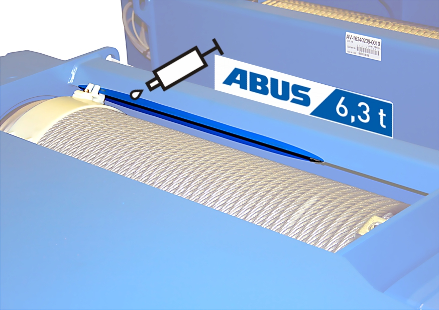
On-site lubrication with “Molykote PG-75”, ABUS item number 5168.
Lubrication ex works with “Molykote PG-75”, ABUS item number 411.
Lubricate the rope guide runner during:
- Wire rope change
- Cable guide change
- Regular inspection
- General overhaul
For details, see “Replacing the wire rope”.
Load hook crosshead on the bottom block
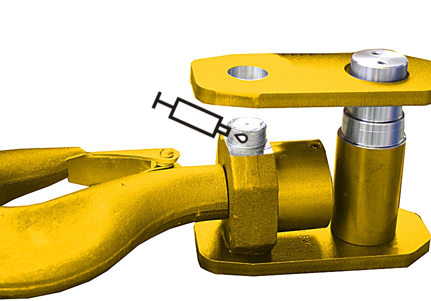
On-site lubrication with “High temperature paste PBC 1574”, ABUS item number 6758.
Lubrication ex works with “High-Lub LT1 EP”, ABUS item number 317880.
Lubricate the load hook crosshead during:
- Assembly and disassembly
- General overhaul
Deep groove ball thrust bearing on the load hook
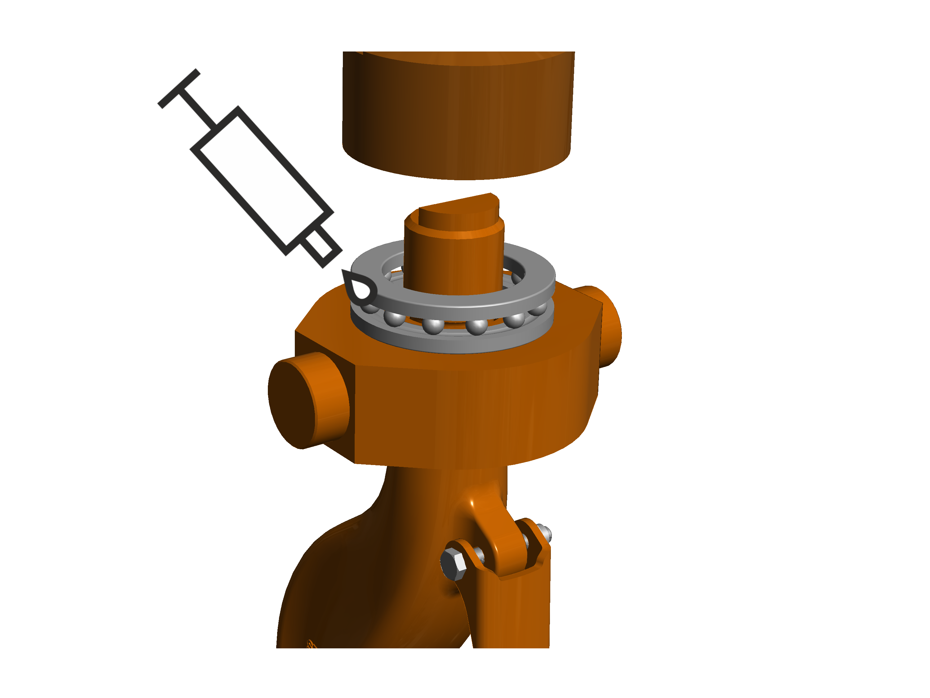
On-site lubrication with “Molykote PG-75”, ABUS item number 5168.
Lubrication ex works with “High-Lub LT1 EP”, ABUS item number 317880.
Lubricate the deep groove ball thrust bearing during:
- Assembly and disassembly
- General overhaul
Rope socket
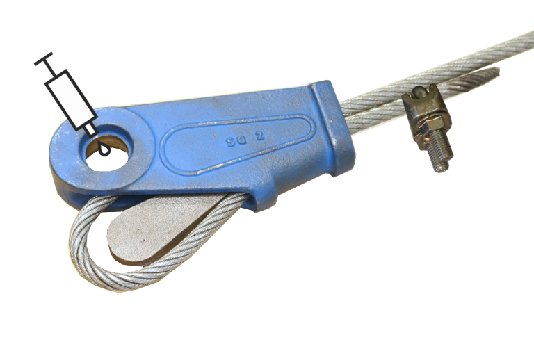
On-site lubrication with “High temperature paste PBC 1574”, ABUS item number 6758.
Lubrication ex works with “High-Lub LT1 EP”, ABUS item number 317880.
Lubricate the rope socket during:
- Wire rope change
- Regular inspection
- General overhaul
For details, see “Exchanging the fixed point crosshead with rope socket and rope wedge”.
Cable guide
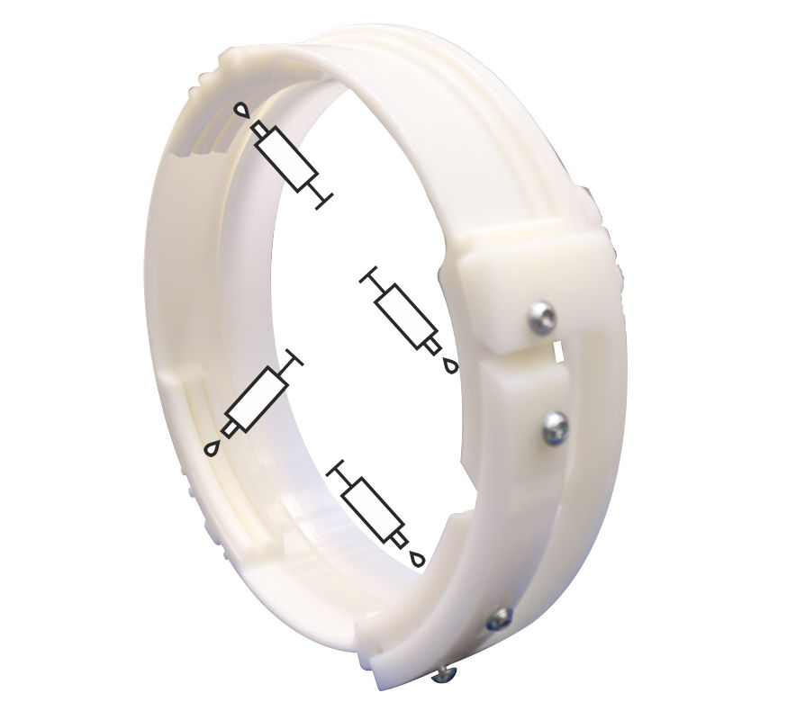
On-site lubrication with “Molykote PG-75”, ABUS item number 5168.
Lubrication ex works with “Molykote PG-75”, ABUS item number 411.
Lubricate the cable guide in case of:
- Wire rope change
- Cable guide change
- Regular inspection, at least once annually
- General overhaul
For details, see “Installing the cable guide”.
Bearing bush (on collar bolt) on the deflection roller crosshead and on the fixed point crosshead
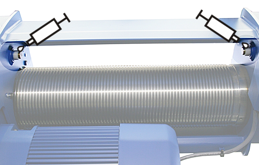
On-site lubrication with “High temperature paste PBC 1574”, ABUS item number 6758.
Lubrication ex works with “High-Lub LT1 EP”, ABUS item number 317880.
Lubricate bearing bush (on collar bolt) during:
- Assembly and disassembly of the deflection roller crosshead or fixed point crosshead
- General overhaul
For details, see “Exchanging the fixed point crosshead with rope socket and rope wedge” or “Exchanging the deflection roller crosshead”.
Overview of tightening torques
End clamp
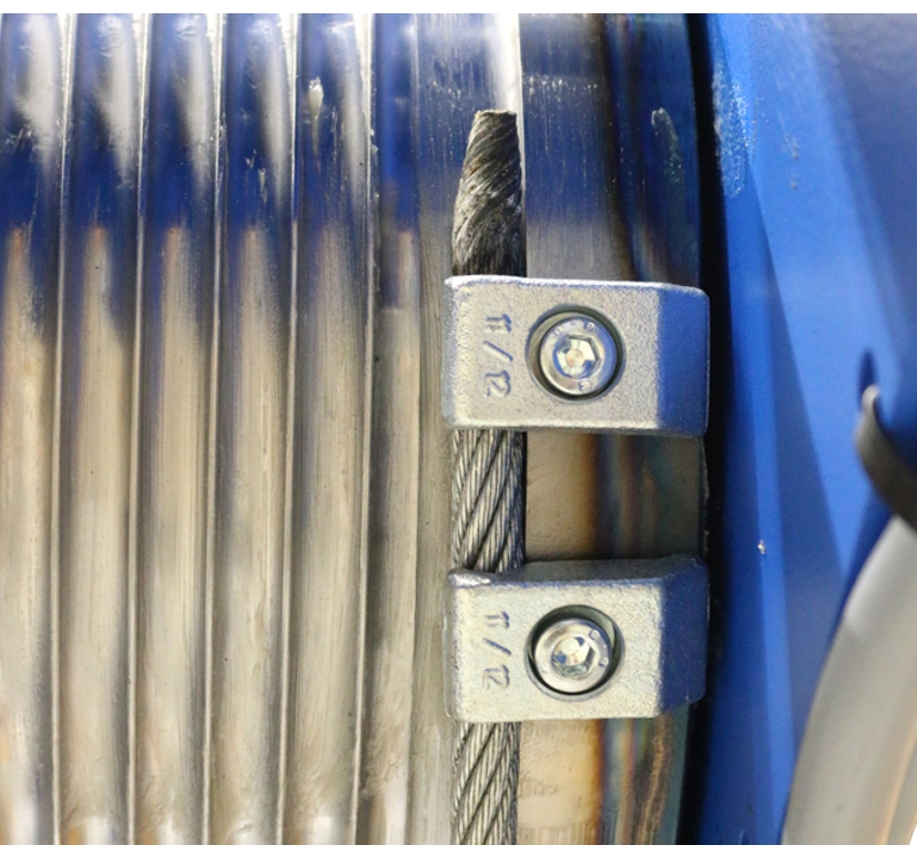
Size |
Fillister-head screw |
Number |
Tightening torque |
|---|---|---|---|
GM 800 |
M6x16 |
2 |
10 Nm |
GM 1000 |
M8x20 |
2 |
25 Nm |
GM 2000 |
M8x20 |
2 |
25 Nm |
GM 3000 |
M8x20 |
2 |
25 Nm |
Rope guide runner
Size |
Screw |
Tightening torque |
|---|---|---|
GM 800 |
Self-tapping screw M6x16 |
5 Nm |
GM 1000 |
Self-tapping screw M6x16 |
5 Nm |
GM 2000 |
Self-tapping screw M6x16 |
5 Nm |
GM 3000 |
Self-tapping screw M6x16 |
5 Nm |
Joining element
Size |
Screw |
Number |
Tightening torque |
|---|---|---|---|
GM 800 |
Self-tapping screw M6x16 |
4x |
5 Nm |
GM 1000 |
Self-tapping screw M6x16 | 4x |
5 Nm |
GM 2000 |
Self-tapping screw M6x16 | 4x |
5 Nm |
GM 3000 |
Self-tapping screw M6x16 | 4x |
5 Nm |
Dead end rope grip
Size |
Rib nut |
Tightening torque |
|---|---|---|
GM 800 |
M6 |
5 Nm |
GM 1000 |
M8 |
10 Nm |
GM 2000 |
M8 |
10 Nm |
GM 3000 |
M8 |
10 Nm |
ABUS Service
Only in Germany
- If available, have the product number, serial number and customer number handy.
- Call the ABUS Service Centre:
- Phone: +49-2261-37-237
- If calling outside the usual business hours, leave a message on the answering machine.
- ABUS Service will return your call promptly.
- If necessary, send a description of the problem by fax or e-mail:
- Fax: +49-2261-37-265
- E-mail: service@abus-kransysteme.de
Only outside Germany
- Call the local ABUS branch or crane service partner.
Your local ABUS branch or crane service partner will provide details of contact data, contacts and availability.