
AT A GLANCE:
General information
This section applies to anyone who lifts loads using the crane, performs work on the crane, or works nearby.
At the start
Using this product manual
The following symbols are used in this product manual:
- This is an instruction regarding an action and prompts you to perform a work step.
- This is the result of an action and describes what happens on the device.
- This is a list.
Only with...
A section that appears in a box framed by a dashed line is only applicable for certain types, versions or options. The condition to which the section applies is specified at the beginning in the heading “Only with...”.
Instructions for the product manual
Read the product manual through carefully before beginning work. Also be sure to observe additional product manuals for accessories and components.
Afterwards, keep the product manual available in the vicinity of the crane. It must be accessible to all who work with or on the crane.
In the case of reselling or hiring out, always provide the product manual together with the crane.
Proper use
The HB crane installation is suitable for lifting and lowering as well as all-round or linear moving of lightweight loads.
- The HB crane installation is also fixed to a hall ceiling or other supporting structure (steel structure, building support, etc.).
- The supporting structure must be designed and constructed to withstand the expected loads. The relevant documentation (e.g. structural design documents, welding instructions, proof of suitability for welding) must be enclosed in the test log book of the HB crane installation.
- An individual calculation created with the ABUS program ABUKonfis must be performed for every HB crane installation. All results of this calculation (e.g. suspension distances, layout of profile rail sections, position and type of suspension, etc.) must be precisely observed. Any changes made to the HB crane installation will require this calculation be performed again.
- The HB rail profile is designed only for the installation of the intended HB crane. The HB crane installation may not be used to move objects or devices directly
- The HB crane installation may not be combined with crane components of other crane manufacturers.
- For expansions or reconstruction, only ABUS components may be used.
Regulations
The installation has been built and tested according to European standards, rules and regulations applicable at the time of its manufacture. The conventions applied during design and construction are specified in the Declaration of Conformity or the Declaration of Incorporation. The conventions must also be observed for installation, operation, inspection and maintenance, as must the applicable occupational health and safety regulations.
Which provision applies in individual cases will greatly depend on the crane’s use and the national regulations. Review and observe all applicable and current regulations, including the occupational health and safety regulations. Refer also to the Declaration of Conformity or Declaration of Incorporation.
Warranty
- ABUS assumes no liability for damages that were caused by improper use, inadequately trained personnel, incorrect performance of work, nor for any changes, reconstruction or other modification of the crane or crane components which were not approved by ABUS.
- Any warranty claim becomes invalid if components were modified without consent, the crane or crane components were installed, used or serviced in any way other than that described in this product manual, or if parts other than original ABUS replacement parts were used.
- Safe operation of the crane or crane components is only guaranteed if original ABUS replacement parts are used.
The HB crane installation
Device description
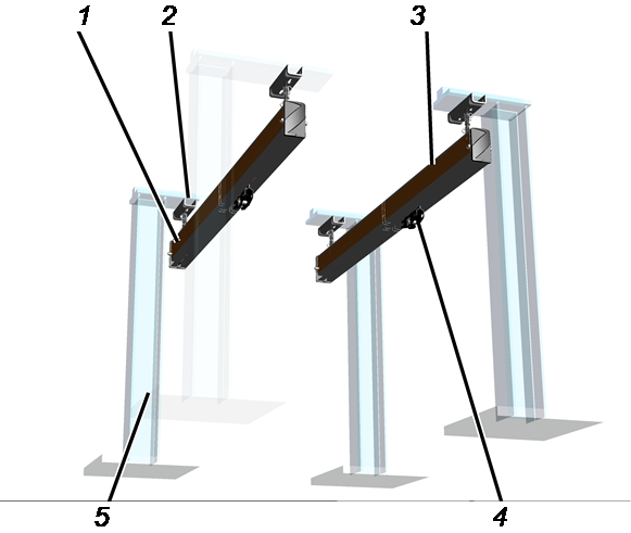
HB profile rail as crane track for the HB cranes EHB, ZHB, ZSK, EHB-X and ZHB-X
Overall view:
Detailed view:
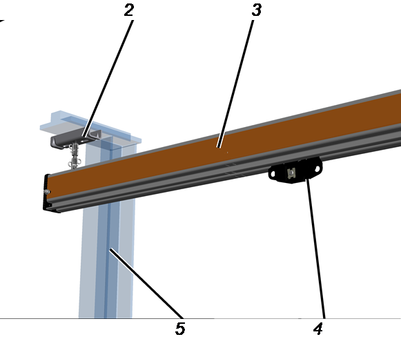
- 1: HB crane runway, left crane track
- 2: Ceiling connection (shown here: flange clamp version)
- 3: HB crane runway, right crane track
- 4: Crane trolley
- 5: Supporting structure (shown here: cantilever support)
Device description
HB profile rail as crane track for single-rail trolley ESK
Overall view:
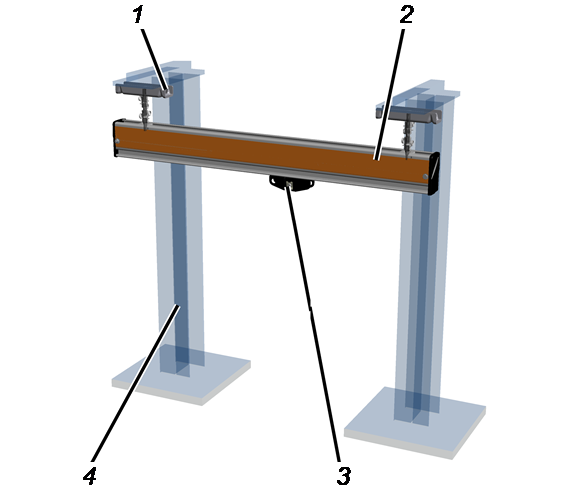
- 1: Ceiling-mounted bracket (shown here: flange clamp version)
- 2: Crane track
- 3: Hoist trolley
- 4: Supporting structure (shown here: cantilever support)
Performance features
The HB system:
- The HB system is a well-organised assortment of crane components whose modular construction enables you to put together individual crane installations.
- In order to take all the characteristics of the building into account, every HB crane installation is adapted to the specific application and calculated with customer-specific parameters.
The HB profile rails:
- The sizes HB110, HB150, HB190 and HB240 are available in the overall HB system.
- Depending on the application case, the HB profile rails are each available as extruded aluminium HB profile rails in the sizes HB150 and HB190 (indicated by A in the product designation) or as one-piece cold-rolled steel HB profile rails in the sizes HB110, HB150, HB190 and HB240 (indicated by an S in the product designation).
- Depending on the application case, the following HB profile rails are available:
Steel HB profile rail |
Aluminium HB profile rail |
|
|---|---|---|
HB crane runway |
HB110, HB150, HB190, HB240 |
HB150, HB190 |
EHB |
HB110, HB150, HB190, HB240 |
HB150, HB190 |
ZHB |
HB150, HB190, HB240 |
HB150, HB190 |
EHB-X |
HB150, HB190, HB240 |
|
ZHB-X |
HB150, HB190, HB240 |
|
EHB-I |
HB150, HB190, HB240 |
HB150, HB190 |
ZHB-I |
HB150, HB190, HB240 |
HB150, HB190 |
- Thanks to a single-piece rolling process, the steel HB profile rails have increased precision and an optimised travel gap geometry that is comparable to aluminium HB profile rails. This noticeably reduces the rolling resistance during manual movements.
- The HB profile rails in the size HB240 have crosswise screw fittings installed inside and rolled-in beading. This provides the HB profile rails with an optimal weight for greater stiffness, which has a favourable effect on the loads placed on the supporting structure while ensuring easier travel on the crane girder.
- The HB profile rails can be connected with each other at any position
using clamping plates. The positions of the suspensions do not have to
be considered. Extensions of HB profile rails are possible without
reconstruction on the existing HB crane installation. The length of the
individual profile rail sections can also be freely selected, which can
be useful in demanding installation situations.
Only with HB240S: there are two different clamping plates available, which are dictated by the distance of the suspension to the profile joint. - The joining of the profile rail sections by means of clamping plates (profile joint) requires only a precise saw cut, but no welding or mechanical processing of any kind. This enables extensions or other modifications of existing HB crane installations to be carried out with less effort.
- The steel HB profile rails are galvanised and laminated at the sides as protection against corrosion. This makes painting them unnecessary.
- In size HB190A, there are curved sections with a radius of 1500 mm available in the angles 10°, 15°, 30°, 45°, 60° and 90°. The curved sections have straight runout ends which allow connections to other profile rail sections to be established using special, short clamping plates.
The craneway suspension:
- The HB profile rails can be mounted on the supporting structure with eight different ceiling connections. The supporting structures can be made of, for example, steel, wood or concrete.
- The ceiling-mounted brackets for the ceiling connection with two load
application points (2LP) are available in three widths (type A, B and
C).
In addition, there is a ceiling-mounted bracket with four load application points (4LP). These have four flange clamps for distributing the load on the supporting structure over four points rather than two. This allows more demanding on-site conditions in the building (e.g. building statics) to be taken into account. The ceiling-mounted bracket 4LP is likewise offered in three widths (type A, B and C). - Depending on the forces introduced, the craneway suspension consists of threaded rods and connection elements in size M16 or M20, with respectively matching profile links and bearing elements for the ceiling-mounted brackets and HB profile rails. The ceiling-mounted brackets are thus available in the versions 2LP/M16, 2LP/M20 and 4LP/M20.
- The HB profile rails are freely suspended from the supporting structure. This enables the entire HB crane installation to absorb the dynamic loads so they are not fully transferred to the supporting structure.
- The HB profile rails are also connected with the supporting structure by flexible and maintenance-free profile connections with rubber mountings.
- The profile connections can be installed in the HB profile rails from above. This reduces the effort required in assembly, especially in the case of expansions and reconstruction.
- Because the HB profile rails can have variable heights due to the individually shortened or lengthened suspensions, they can be adapted to fit the supporting structure.
Electrical system of the HB crane installation:
- The entire electrical system has a modular construction to enable easy expansion of the HB crane installation.
- The electric connections of the HBF drives, the chain hoist and all other components are of a plug-in type for fast assembly, replacement and reconstruction of the HB crane installation.
- For conductor systems: in contrast to the festoon cable system there is no cable marshalling point, which means the crane stop clearance and the trolley stop clearance at the ends of the crane track are very limited. This also allows transport of loads in the operating range boundaries of the HB crane installation.
Technical data
Dimensions and weights for steel HB profile rails:
Size |
Height |
Width |
Weight per metre |
|---|---|---|---|
HB110S |
110 mm |
66 mm |
12 kg/m |
HB150S |
155 mm |
90 mm |
17.6 kg/m |
HB190S |
185 mm |
90.5 mm |
20.6 kg/m |
HB240S |
250.5 mm |
90.5 mm |
25.2 kg/m |
Dimensions and weights for aluminium HB profile rails:
Size |
Height |
Width |
Weight per metre |
|---|---|---|---|
HB150A |
155 mm |
90 mm |
8.6 kg/m |
HB190A |
185 mm |
90 mm |
11.1 kg/m |
The technical data of the individually calculated HB crane installations are specified in the planning documents.
Noise emissions:
Size |
Sound pressure level LP, m dB(A) at distance of 2 m |
Sound pressure level LW, m dB(A) |
|---|---|---|
HBF520 |
67 |
81 |
HBF1040 |
70 |
84 |
Table: Noise emissions based on DIN 45635, Part 61 following the substitution process with an acoustic power source
In the table, the sound pressure level LP is specified for a distance of 2 m from the HBF drive. To calculate the sound pressure level LW, the sound pressure level at any distance may be used.
Mechanical design life
Existing HB crane installations can be modified in various ways. For this, new components are combined with components that were already in use.
The overall service life of the newly created HB crane installation then corresponds to the remaining service life of the components that had already been in use.
Transporting the HB system on a lorry
Observe the following points amongst others:
- Secure the load according to regional regulations.
- Lay suitable blocks of wood on the loading area beneath the profile rail sections.
- Secure the profile rail sections to the loading area with suitable lifting tackle.
- Also secure individual components and boxes to the loading area using suitable lifting tackle.
- If the profile rail sections are no longer packaged (e.g. in used installations): transport the profile rail sections packaged individually or cover them with a tarp. Otherwise, rainwater could penetrate and white rust could form on the galvanised surfaces.
Storing the HB system
If the HB crane installation is not installed immediately:
- Leave the profile rail sections packaged during storage.
- If the packaging of the wrapped profile rail sections has become wet: leave the profile rail sections in their packaging, but open the packaging so that moisture can escape.
- Wipe off any rainwater.
- Store unpainted metallic parts, chain hoists, electrical and electronic components in a dry, dust-free place.
Only with ceiling connection using dowel plate
If the anchor rods are not installed immediately:
- Store injection mortar in the way specified on the dowel set packaging.
- Clearly allocate the individual parts when storing them. The components must not be replaced with, or be combined with, individual parts for different cranes.
Inspection after lengthier storage
Should the HB crane installation be installed after it has been in storage for a lengthier period:
- Perform a visual inspection of all components. They should be neither heavily soiled nor dusty.
- For painted or coated components: check surfaces. The paint or coating should not be cracked or peeling.
- Check the profile rail sections. The zinc layer should not be damaged or heavily scratched.
- Inspect metallic parts. They should exhibit no rust.
- Inspect electrical components. Live parts (e.g. bushes, pins and terminals) should not be oxidised (e.g. discoloured or roughened surface).
Disposing of the HB system
When disposing of the HB crane installation:
- Dismantle the HB crane installation as far as possible.
- Observe local regulations concerning disposal and recycling.
- Dispose of the individual parts sorted by material in an environmentally sound manner.
- Dispose of profile rail sections, clamping plates, threaded rods and small parts of the crane girder suspension as metal scrap.
- Dispose of the profile link and ceiling-mounted bracket (including rubber mounting) as metal scrap.
- Dispose of the oil from the gear unit as a lubricant.
- Dispose of brake linings and friction clutch linings as multiple components (hazardous waste).
- Dispose of electronic components as scrap electronic parts.
- Dispose of motors as electrical scrap.
- Plastic parts should be recycled with plastic waste.
- Dispose of cables, plug-in connections and pendant controls as scrap electronic parts.

Installing and connecting
This section applies to anyone who works on the crane prior to its use
The end user of the crane is responsible for the proper qualifications of the commissioning personnel.
Examples of qualified persons:
- Persons with comprehensive knowledge from specialist training in engineering and in the electrical systems of cranes.
- Persons with sufficient experience in the operation, installation and maintenance of cranes.
- Persons with comprehensive knowledge regarding the relevant technical rules, directives and safety regulations applicable in the respective country.
- Persons receiving regular training from ABUS.
ABUS assumes no liability for damage due to incorrectly performed commissioning work done by unqualified personnel.
ABUS recommends having the commissioning work performed by the ABUS assembly team.
Checking the requirements
The following requirements must be met in order for the HB crane installation to be installed:
Checking the requirements through a technical pre-clarification
The requirements for assembly of the HB crane installation can be checked by ABUS through a technical pre-clarification.
- The technical pre-clarification is in every case performed if the assembly of the HB crane installation is done by ABUS.
- The technical pre-clarification can also be performed by ABUS if the HB crane installation is done autonomously or through other fitting and installation companies.
- If no technical pre-clarification is performed by ABUS, the following requirements must be independently checked and documented prior to the installation.
Checking the supporting structure
- The supporting structure (building, hall ceiling, building support, etc.) must be able to withstand the expected loads.
- There must be adequate space on the supporting structure for the ceiling connection. Other parts such as lamps, piping, vents, heaters should not interfere with the installation of the ceiling connection.
- If parts that interfere are present, these must be taken into account during the planning of the HB crane installation. In this case, special craneway suspensions are necessary (e.g. V-suspension) in order to evade the interfering parts or the interfering parts must be removed or the craneway suspension planned around these parts.
Checking the planning documents
- All planning documents for the HB crane installation must be present.
ABUS creates and calculates these planning documents separately for each individual HB crane installation (or for the reconstruction of an existing HB crane installation).
The planning documents consist of at least a layout plan, an assembly plan and an overview of the suspensions and ceiling connections.
The planning documents, especially the suspension distances and projections, must in any case be followed exactly.
Only with ceiling connection using anchor connection
Checking the statics of the concrete element
- Have concrete elements (e.g. intermediate deck) checked by a structural engineer.
In doing so, observe at least the following points:
- The concrete element must be of sufficient thickness.
- The quality of the concrete must be adequate.
- The reinforcement cage in the concrete elements should not be damaged during assembly work. If this cannot be ensured, any damage to the reinforcement cage should not negatively affect the structural characteristics.
- The concrete element may be maximally 400 mm in thickness.
Checking the top side of the concrete element
- Check the top side of the concrete element (e.g. floor of the next story above).
In doing so, observe at least the following points:
- The top side may not be covered with anything (e.g. tiles) that cannot withstand the loads.
- The counter plates of the cup square bolts should not protrude.
Only with ceiling connection using dowel plate
- The concrete ceiling must have at least quality B25 (C20/25) and maximally B55 (C50/60).
- The concrete ceiling must be able to withstand the expected loads produced by the HB crane installation.
- The concrete ceiling must be at least as thick as specified in the table. The minimum clearance of the drilled holes to joints and edges must be observed.
Highbond dynamic anchors |
Minimum thickness of the concrete ceiling |
Minimum clearance to joints and edges |
|---|---|---|
M12 |
140 mm |
150 mm |
M16 |
160 mm |
150 mm |
Performing the technical pre-clarification for the installation of the dowel plate
- Perform the separate technical pre-clarification for the installation of the dowel plate using anchor rod and injection mortar.
See “Technical pre-clarification and requirements for dowel fastenings of ABUS suspended rail systems”
Only with normal suspension
Checking the incline of the supporting structure for normal suspensions
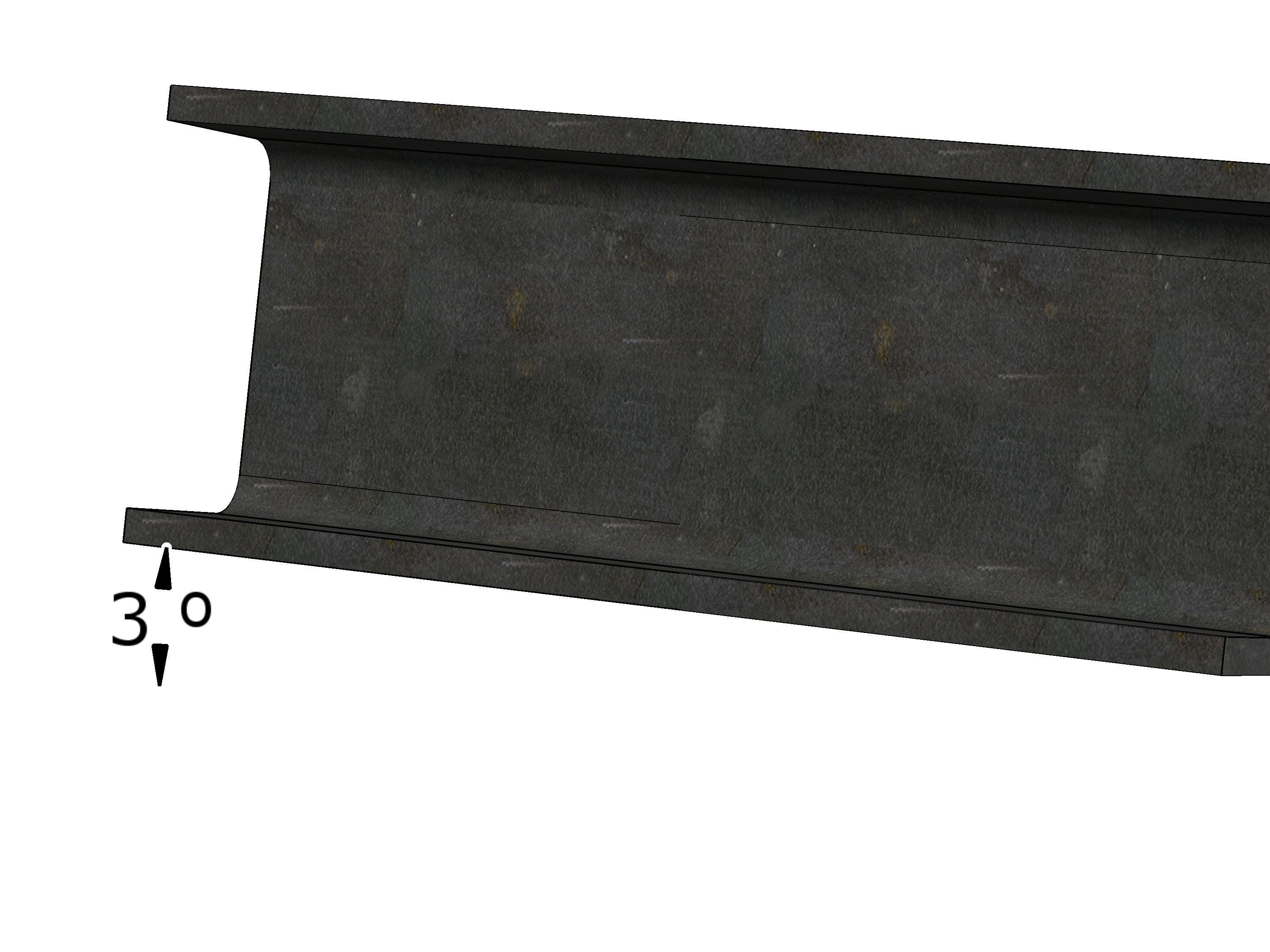
- Check the incline of the supporting structure.
The incline for normal suspensions may be maximally 3° in all directions.
Only with inclined suspension
Checking the incline of the supporting structure for inclined suspensions
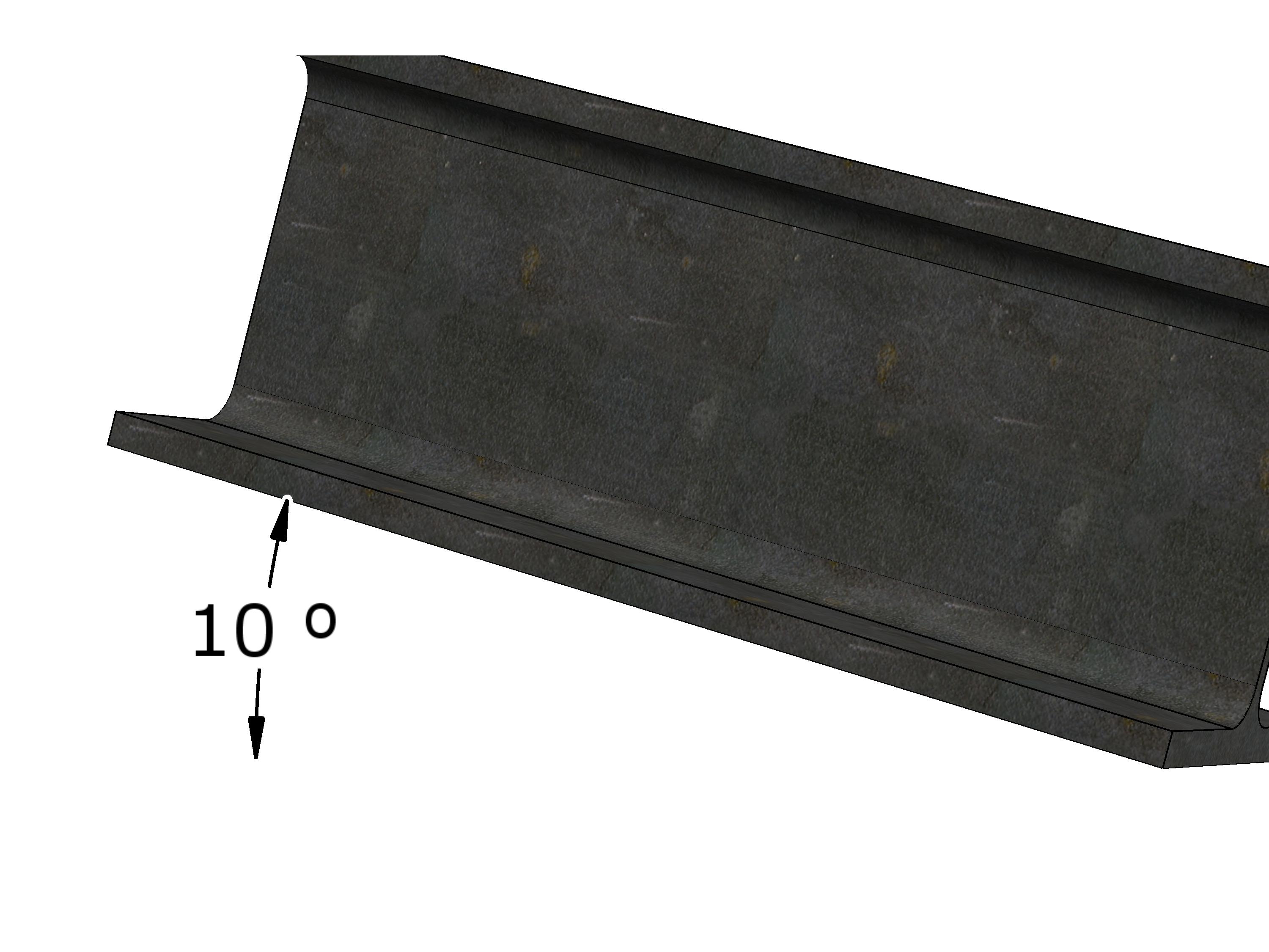
- Check the incline of the supporting structure.
The incline for inclined suspensions may be maximally 10° in all directions.
Checking the flange width
Only with ceiling-mounted brackets 2LP/M16 or M20 with threaded rod
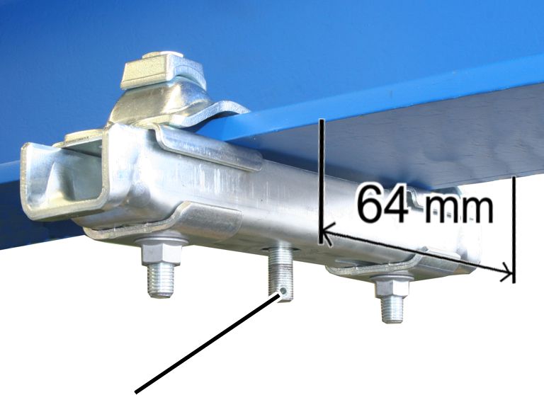
- Check the flange width on the I-beam of the supporting structure.
The flange must be at least 64 mm wide.
Only with ceiling-mounted bracket 2LP/M16 with articulated girder in longitudinal direction
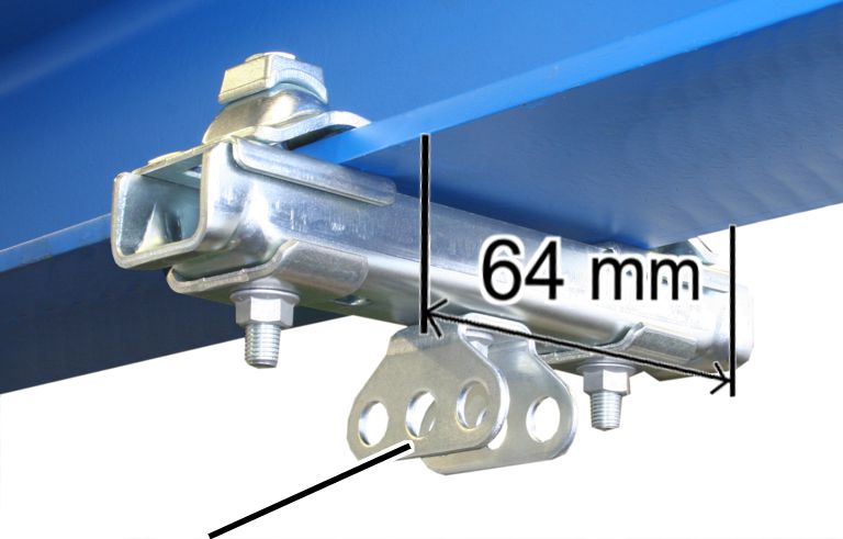
- Check the flange width on the I-beam of the supporting structure.
The flange must be at least 64 mm wide.
Only with ceiling-mounted bracket 2LP/M16 with articulated girder in crosswise direction
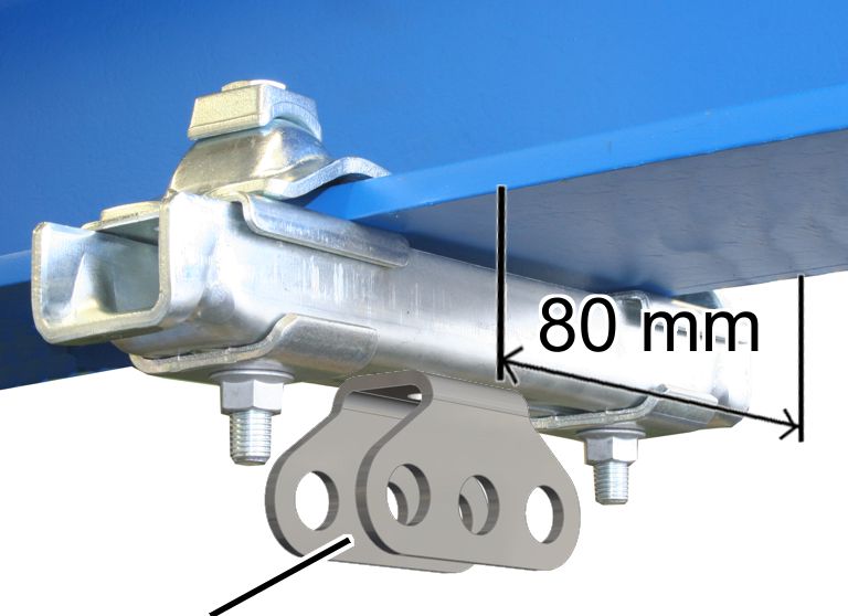
- Check the flange width on the I-beam of the supporting structure.
The flange must be at least 80 mm wide.
Only with ceiling connection using flange clamp
Checking the flange thickness
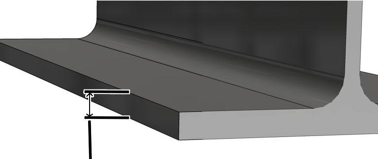
- Check the flange thickness on the I-beam of the supporting structure.
The flange thickness must be between 6 mm and 20 mm.
- If the flange is thicker than 20 mm: special retaining plates must be used in the assembly.
Installation overview of HB crane runway
Note:
This installation overview serves as a point of reference to assist you in the assembly of the entire installation.
For the actual installation instructions: see from “Installing the ceiling-mounted bracket 2LP/M16 or M20: Flange clamp on I-beam”.
The figures show the position of the components on a fully installed HB crane. This serves only as an overview.
Installing the crane track
Supporting structureCeiling-mounted bracket 2LP/M16 or M20
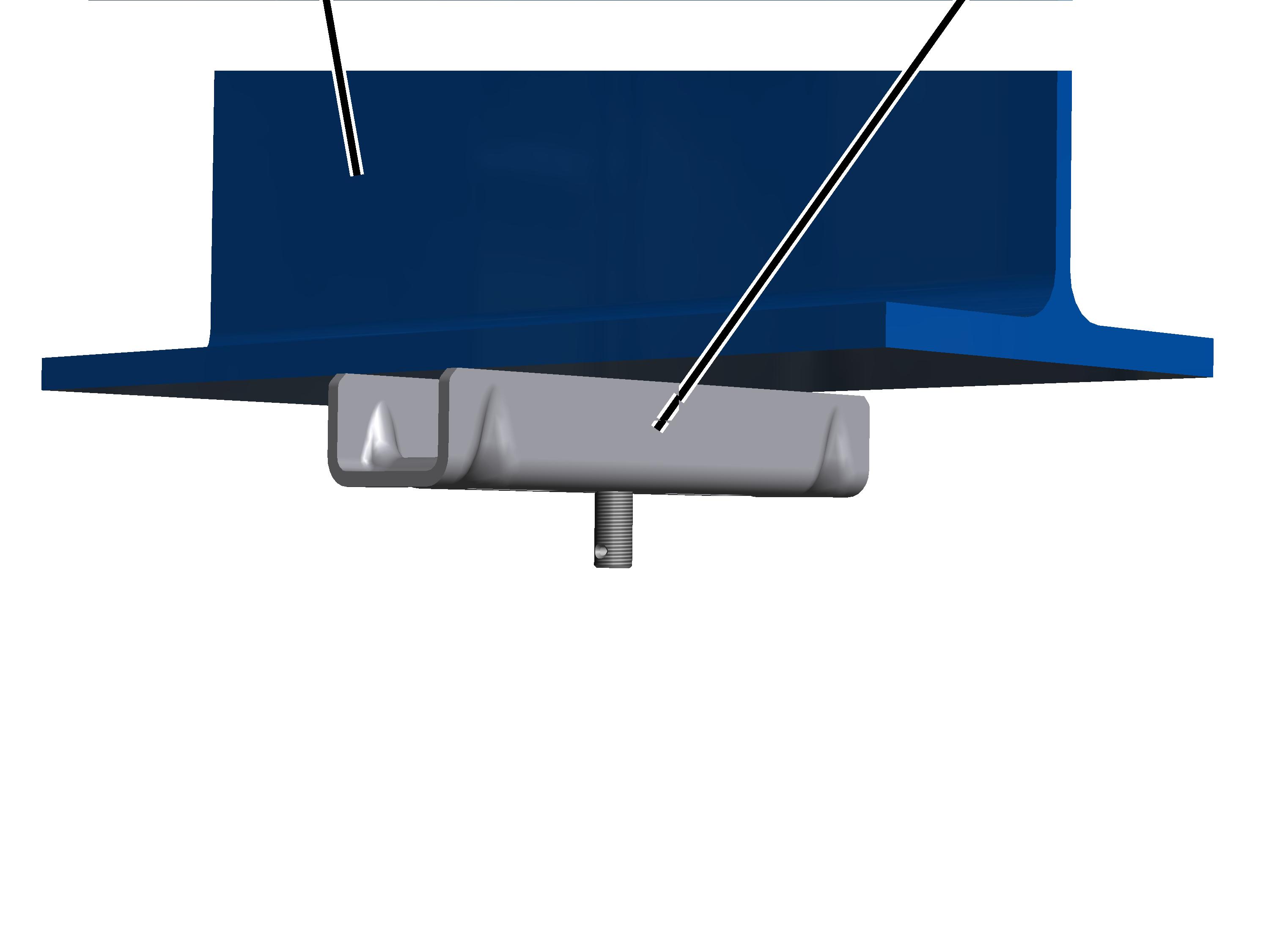
- First, all 2LP/M16 or M20 ceiling-mounted brackets are assembled on the supporting structure.
There are eight different versions for assembling the ceiling-mounted brackets. The supporting structure will determine which version is used:
- With flange clamp on I-beam: see “Installing the ceiling-mounted bracket 2LP/M16 or M20: Flange clamp on I-beam”.
- With weld-on block on steel section: see “Installing the ceiling-mounted bracket 2LP/M16 or M20: Weld-on block”.
- With dowel plate on concrete ceiling: see “Installing the ceiling-mounted bracket 2LP/M16 or M20: Dowel plate”.
- With anchor connection on concrete element: see “Installing the ceiling-mounted bracket 2LP/M16 or M20: Anchor connection on concrete element”.
- On anchor bar: see “Installing the ceiling-mounted bracket 2LP/M16: anchor bar (Halfen channel)”.
- On wooden beam: see “Installing the ceiling-mounted bracket 2LP/M16 or M20: clasping the wooden beam”.
- With rib nut: see “Installing the ceiling-mounted bracket 2LP/M16 or M20: bolting on with rib nuts”.
- With rib screw: see “Installing the ceiling-mounted bracket 2LP/M16 or M20: bolting on with rib screw”.
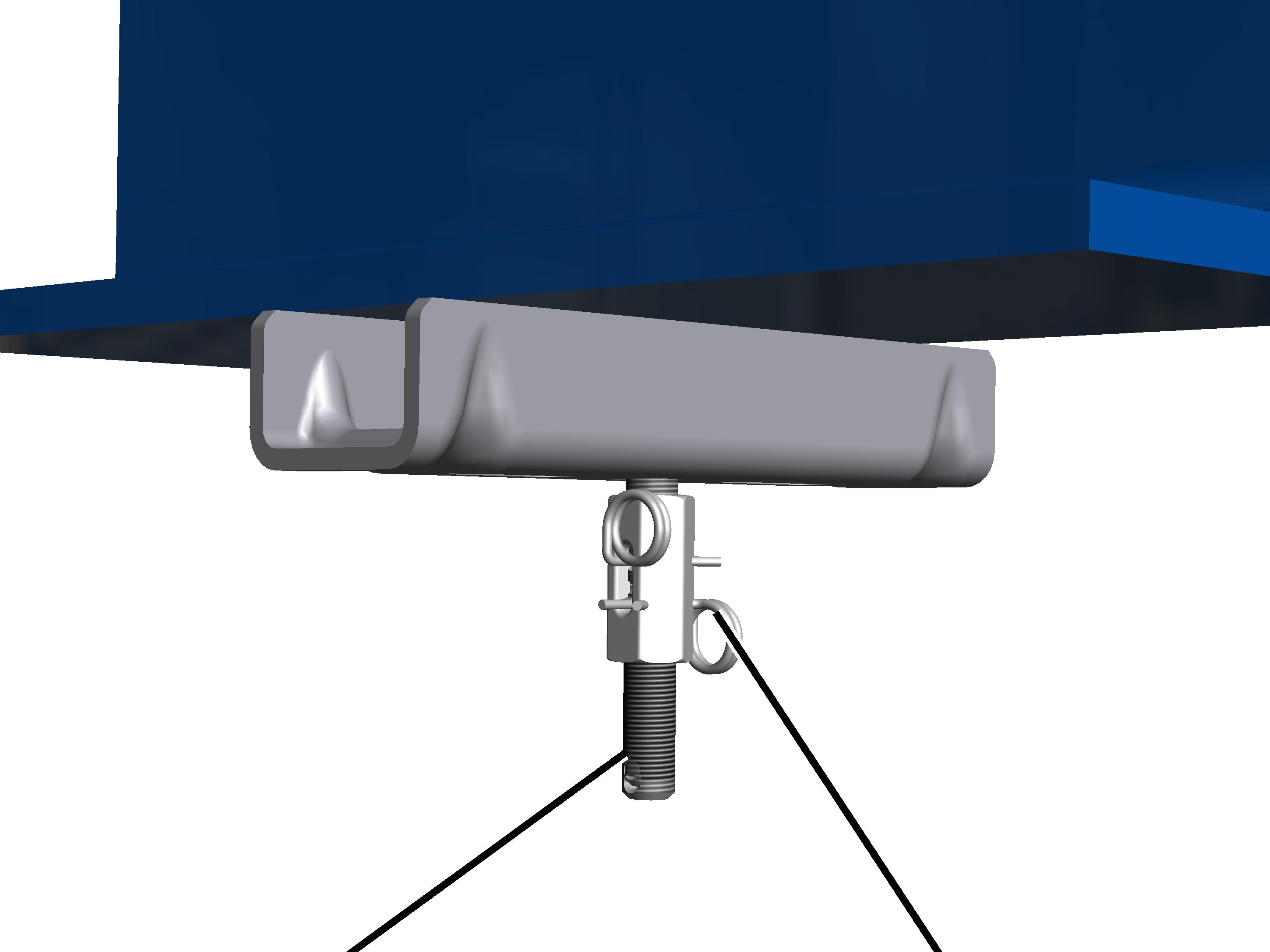
- The threaded rods with which the crane track is later hung on the ceiling-mounted brackets are then shortened or lengthened. See “Shortening or lengthening threaded rods”.
- Next, the suspension is installed on the ceiling-mounted brackets.
There are six different suspensions. Which version is used is in part determined by the supporting structure and the suspension height of the HB crane installation.
- Normal suspension: see “Craneway suspension M16: installing a normal suspension”.
- Short suspension: see “Craneway suspension M16: Installing a short suspension”.
- Inclined suspension: see “Craneway suspension M16: installing an inclined suspension”.
- Normal stiffener: see “Craneway suspension M16: installing a normal stiffener”.
- Inclined stiffener: see “Craneway suspension M16: installing an inclined stiffener”.
- V-suspension: see “Craneway suspension M16: installing the V-suspension”.
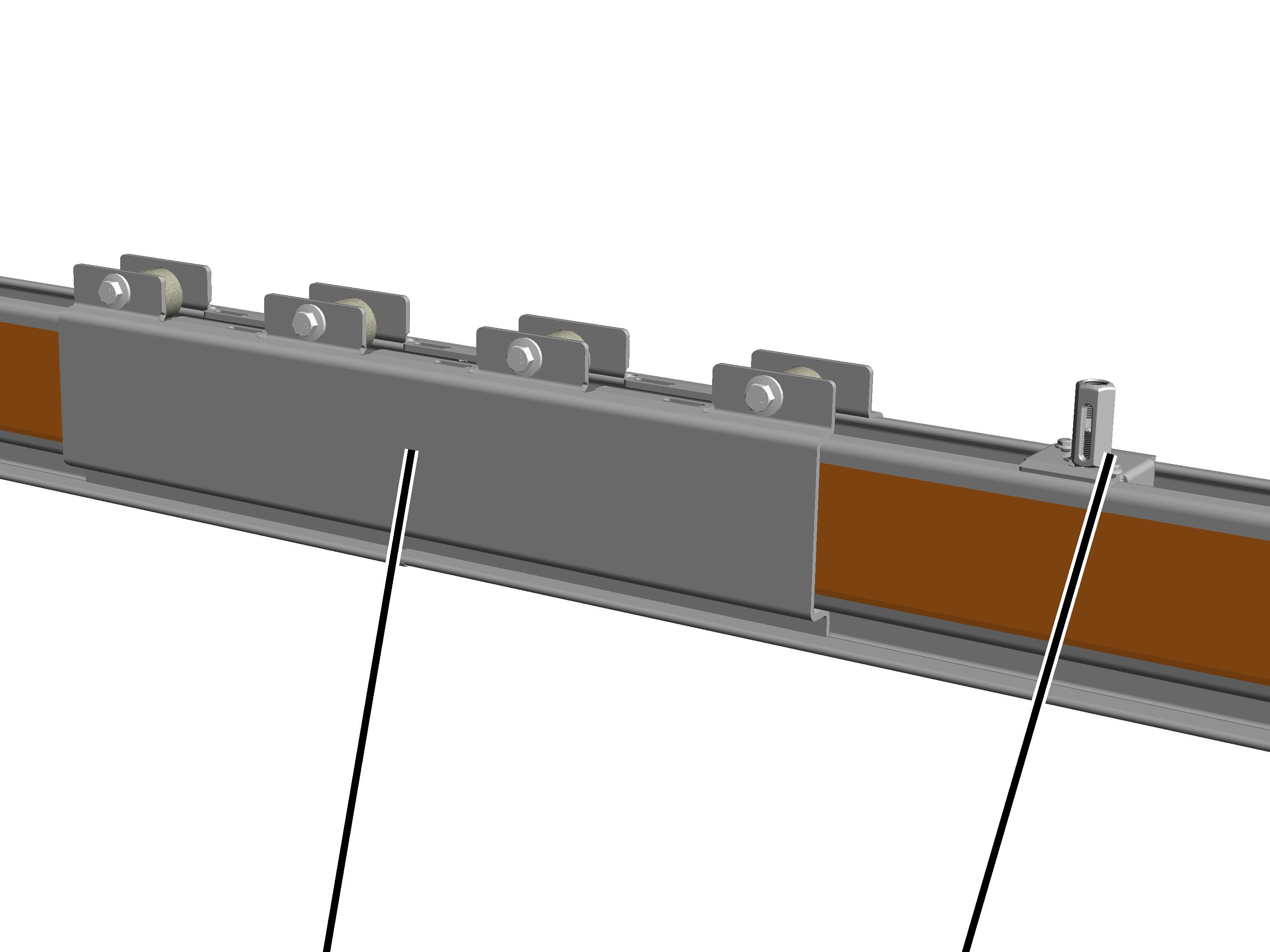
- Next, the individual profile rail sections are joined together for the crane track. See “Connecting steel profile rail sections”.
- Especially with reconstructions, it may be necessary to shorten the profile rail sections on-site.
See “Sawing profile rail sections”.
Normally the profile rail sections are cut to the corresponding length for the specific order. This eliminates the need to cut the profile rail sections on-site.
- The profile connections are then laid loosely in the HB profile rails. The profile connections are not bolted on so that they can later be moved freely for installation. See “Installing profile connections for craneway suspension M16”.
Depending on the length of the individual profile rail sections, the number of suspensions, the on-site building conditions and the length of the crane track, several profile rail sections should be connected with each other on the floor if possible.
The connected profile rail sections must be able to be raised and brought underneath the suspensions safely and without posing additional hazards.
If this is not possible, the profile rail sections must first be fixed individually or partially joined to the suspension and then afterward fully joined with each other. When doing this, it must be ensured that there is adequate space underneath the suspensions, especially in the case of short suspensions.
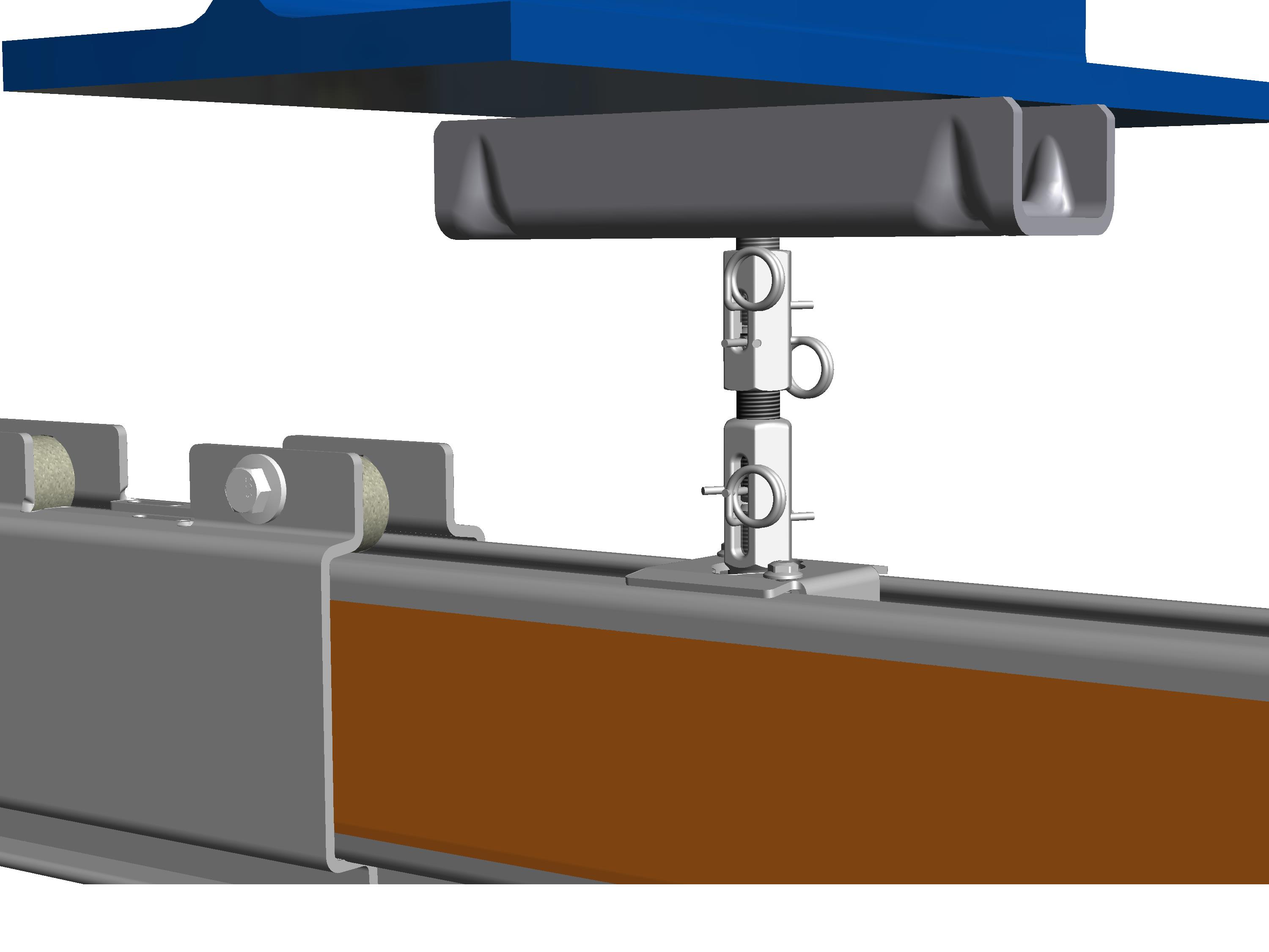
- The crane track is then bolted to the suspension together with the profile connections. See “Installing the HB crane runway on the M16 craneway suspension”.
- Next, the crane track is aligned. See “Aligning the crane track”.
- Finally, the crane track is tightly bolted and secured. See “Bolting on and securing the crane track to the craneway suspension”.
Only with festoon cable system and conductor system VKL
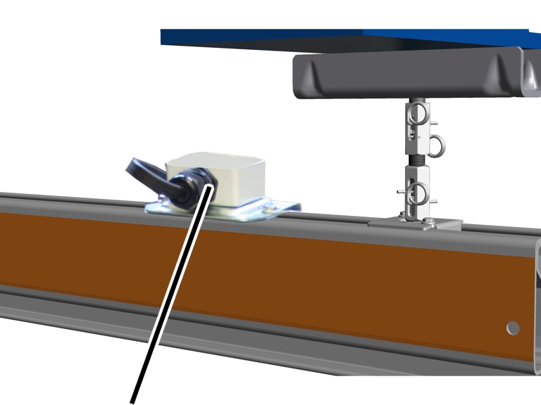
- A terminal box is mounted on the power line on the crane track. See “Installing the terminal box”.
- The travel mechanisms for crane (EHB, ZHB) or trolley (ESK, ZSK) are then inserted in the crane track. See “Inserting the trolleys”.
- If necessary, the HBF drives are then installed. See “Installing the HBF drive”.
- If necessary, the anti-collision devices are next inserted in the crane track. See “Installing the anti-collision device”.
- The mains power supply is then installed on the crane track.
There are three different versions of the mains power supply.
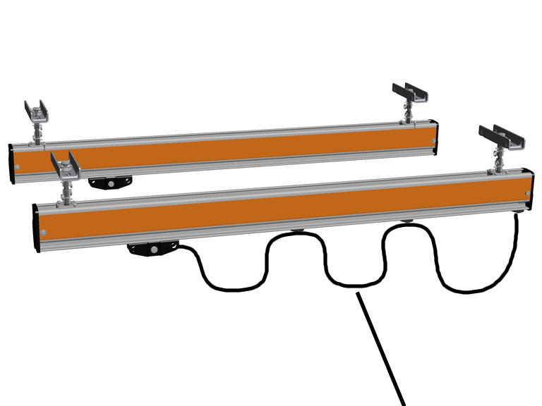
- Festoon cable system: the mains power supply consists of a flat cable
which is fastened to cable sliders. These cable sliders are then pulled
along by the HB crane.
See “Installing the festoon cable system”.
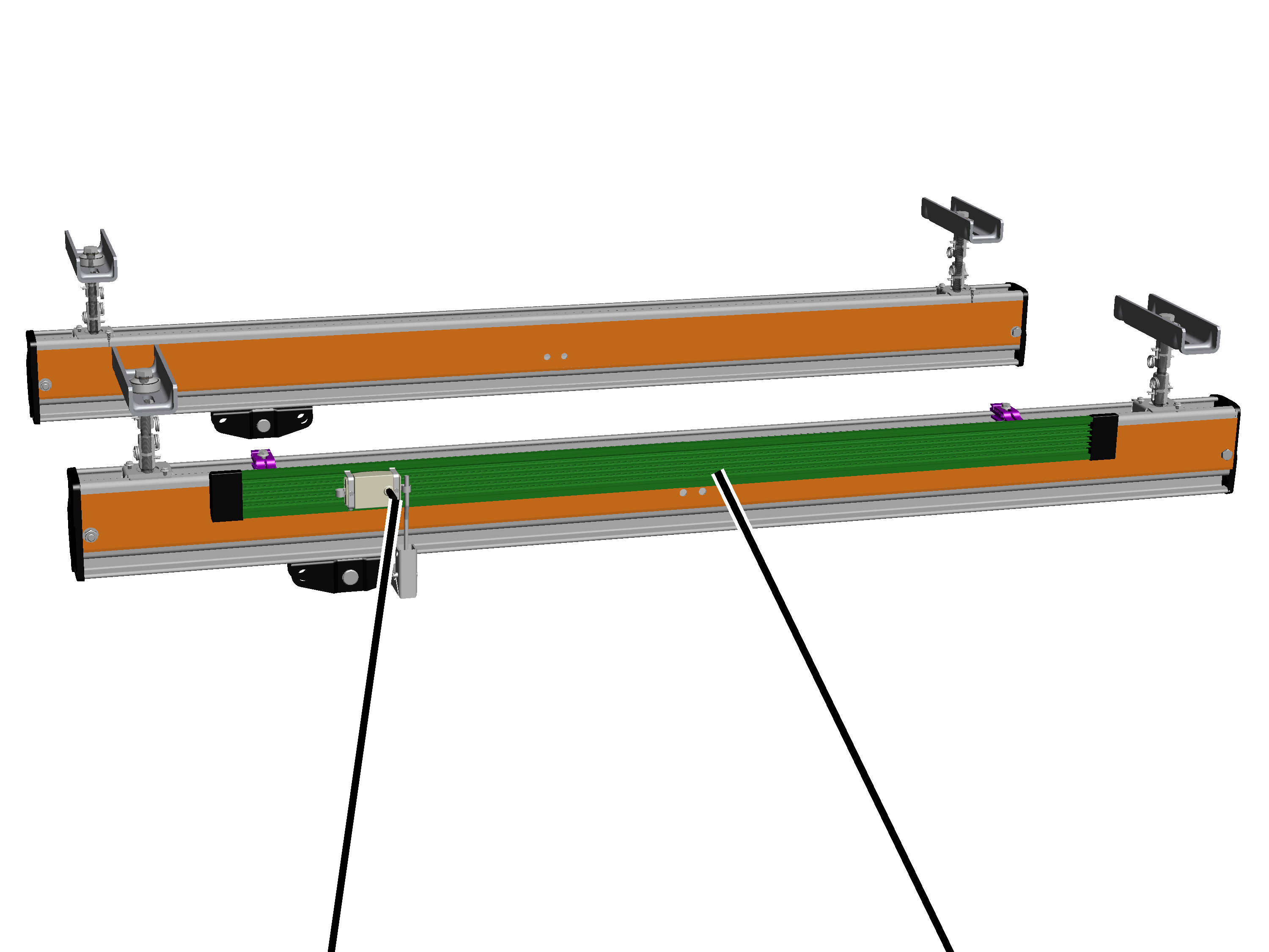
- Conductor system VKL (not with HB240): the mains power supply consists
of a conductor system which is mounted on the crane track. In the
conductor system, a current collector is pulled along by the HB
crane.
See “Installing the conductor system VKL”.
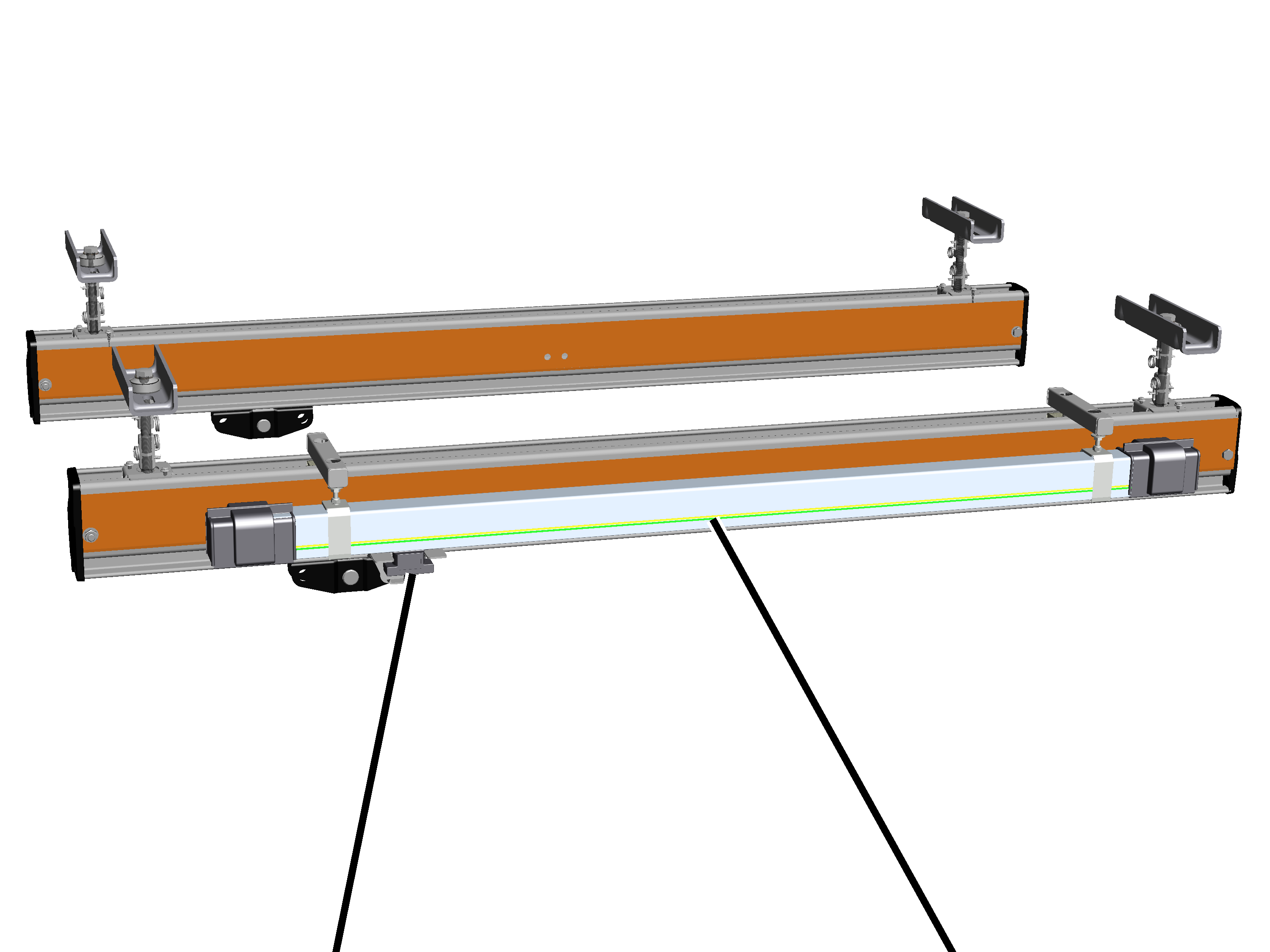
- Conductor system KBH: the mains power supply consists of a conductor
system which is mounted on the crane track. In the conductor system, a
current collector is pulled along by the HB crane.
See “Installing the conductor system KBH”.
- For the double-rail trolley ZSK there is a further variant of the mains power supply available. This is described in the product manual “Installing the HB crane ZHB or ZSK”.
- Finally, the mains power supply is connected. See "Connecting the mains power supply".
Installing the ceiling-mounted bracket 2LP/M16 or M20: Flange clamp on I-beam
The ceiling-mounted bracket 2LP/M16 or M20 is clamped with two flange clamps on the lower flange of an I-beam.
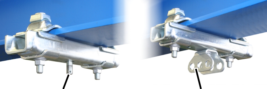
Only with ceiling-mounted bracket 2LP/M16 with articulated girder
This section only applies to the ceiling-mounted bracket 2LP/M16 with bolted-on articulated girder (with normal stiffener, inclined suspension, inclined stiffener and V-suspension).
Turning the articulated girder
On every ceiling-mounted bracket 2LP/M16 with articulated girder:
The articulated girders can be mounted lengthwise or crosswise to the ceiling-mounted bracket 4LP/M20 as appropriate for the alignment of the supporting structure.
Ceiling-mounted bracket
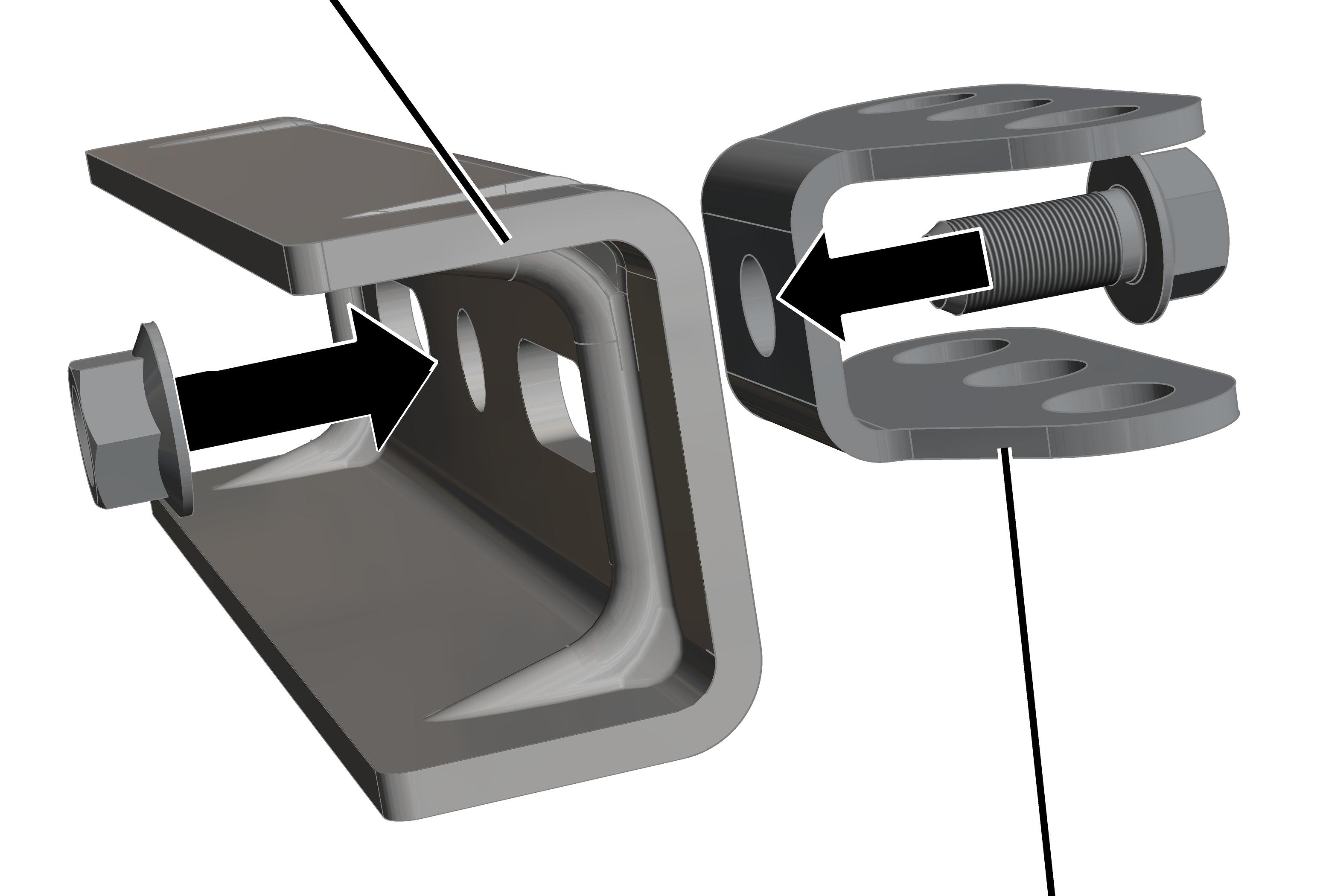
- Insert M16x35 rib screw through articulated girder.
- Insert articulated girder with rib screw in ceiling-mounted bracket.
- Screw the M16 rib nut loosely onto the rib screw from the back.
- Shift the articulated girder lengthwise or crosswise to the ceiling-mounted bracket as necessary.
- Screw the rib nut on. Tighten to 300 Nm.
Assembling the flange clamp
Two per ceiling-mounted bracket 2LP/M16 or M20:
Clamping plateClamping bracket with head plate
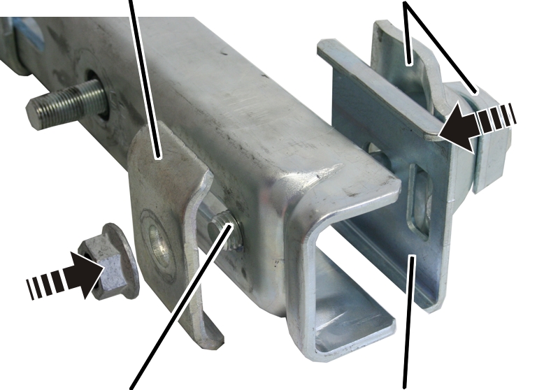
- Slide the head plate, clamping bracket and retaining plate onto the M16x30 hexagon head screw.
- Push the hexagon head screw through the ceiling-mounted bracket.
- Insert the clamping plate from below.
- Screw the M16 rib nut loosely on the hexagon head screw.
Clamping bracketLug
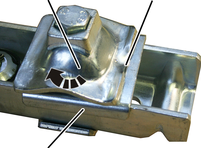
- Turn clamping bracket: the lug of the clamping bracket should clamp in the opening of the retaining plate.
Only with flange thicknesses of at least 20 mm
This section only applies if the flange of the I-beam is thicker than 20 mm.
Two per ceiling-mounted bracket 2LP/M16 or M20:
Clamping plateHexagon head screw
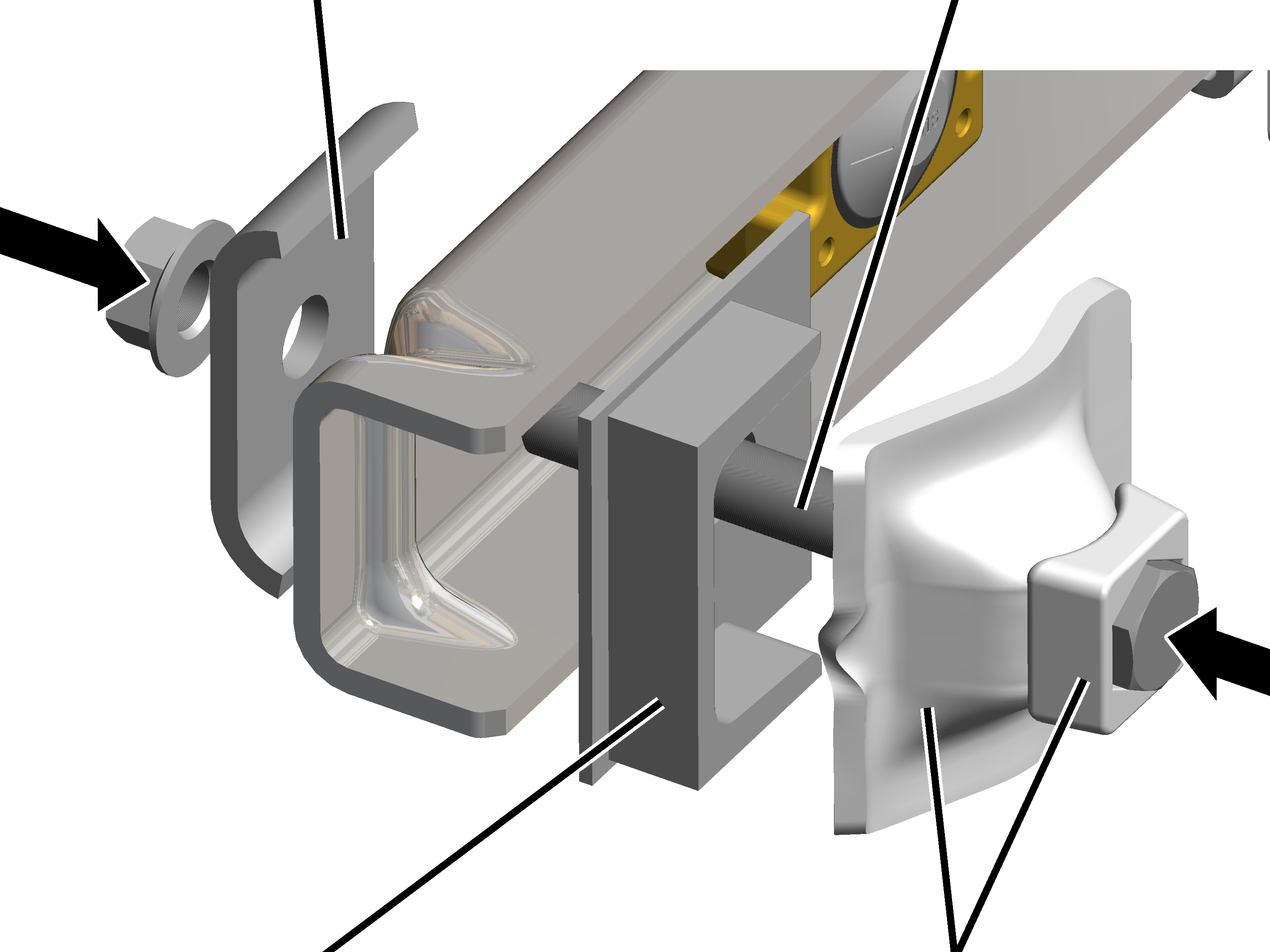
- Slide head plate, clamping bracket and retaining plate for thick flange onto M16 hexagon head screw.
- Push the hexagon head screw through the ceiling-mounted bracket.
- Insert the clamping plate from below.
- Screw the M16 rib nut loosely on the hexagon head screw.
Clamping bracketLug
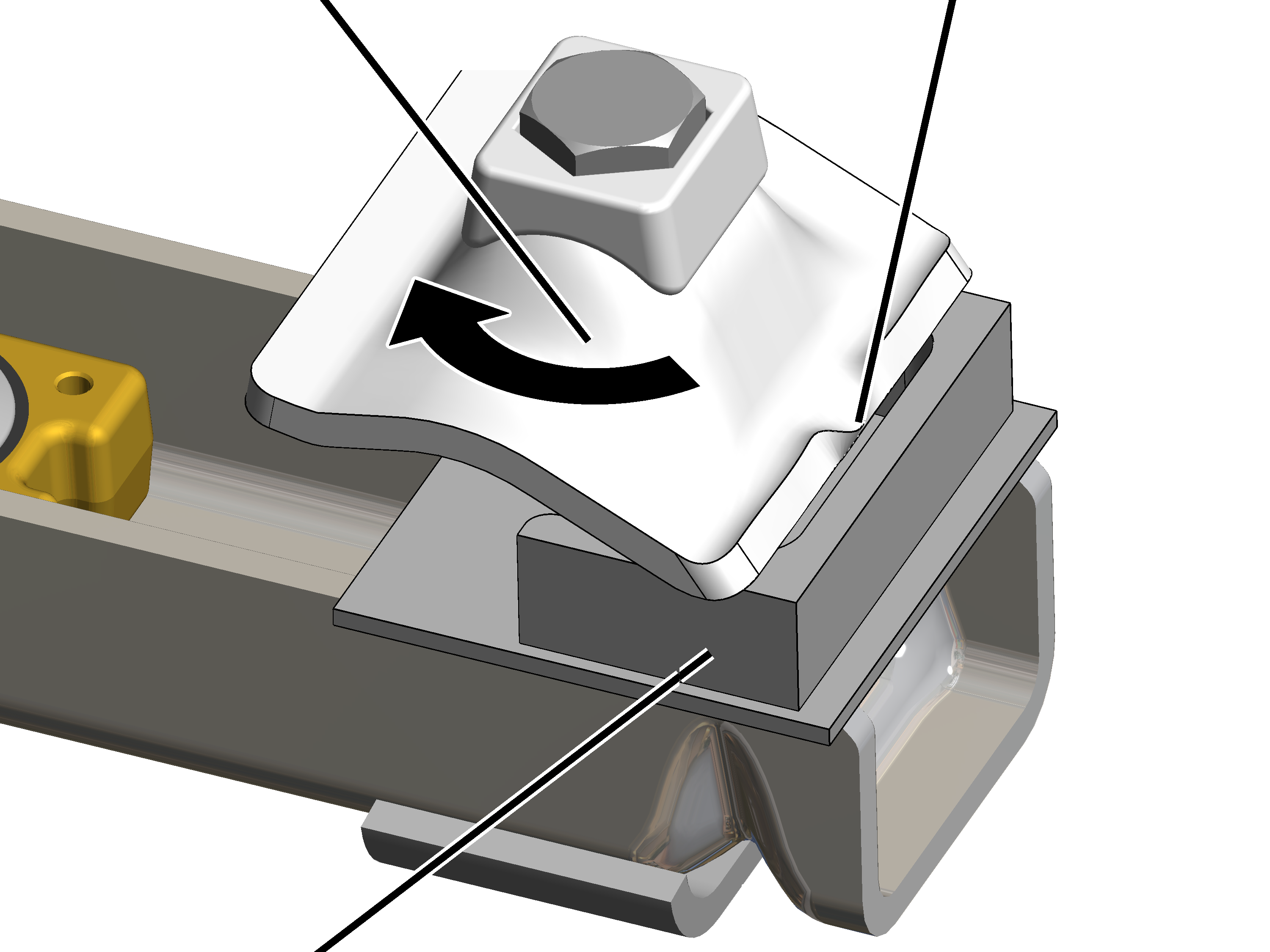
- Turn clamping bracket: the lug of the clamping bracket should clamp in the welded-on U-profile on the retaining plate.
Mounting the flange clamp
On every ceiling-mounted bracket 2LP/M16 or M20:
The specified dimensions, positions and clearances must be followed exactly.
Flange clamps
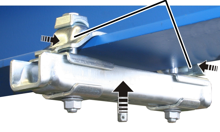
- Push the ceiling-mounted bracket with flange clamps onto the I-beam.
Ceiling-mounted bracket centred in relation to HB profile railCeiling-mounted bracket perpendicular to HB profile rail
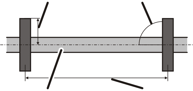
- Align the ceiling-mounted bracket so that it lies lengthwise exactly perpendicular to the later-installed HB profile rail.
- Position the ceiling-mounted bracket so that it is exactly centred in relation to the later-installed HB profile rail.
This is necessary so that the HB profile rail can later be aligned.
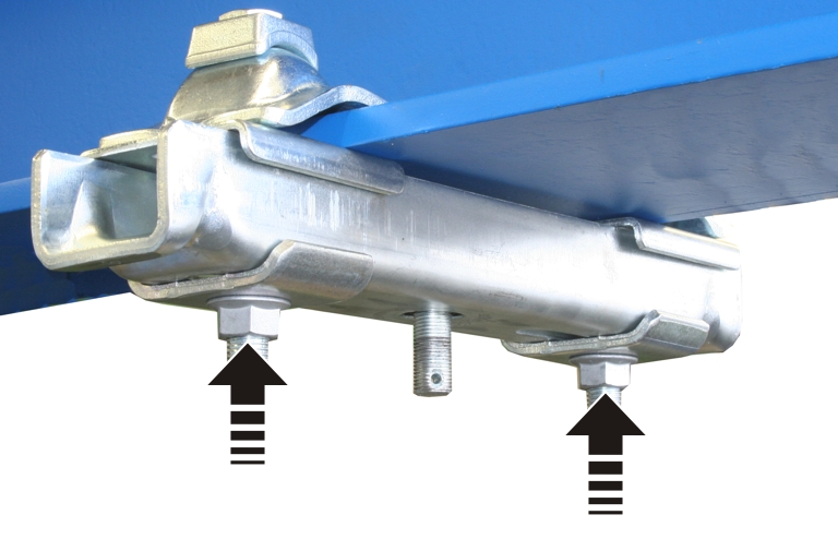
- Screw on the M16 rib nuts (2x) initially hand-tight.
The rib nuts will later be tightened to the correct tightening torque (after aligning the HB profile rail).
If final alignment of the ceiling-mounted bracket 2LP/M16 or M20 can now be done:
- Screw the rib nuts tight to 200 Nm.
Installing the ceiling-mounted bracket 2LP/M16 or M20: Weld-on block
The ceiling-mounted bracket 2LP/M16 or M20 is not directly welded onto the supporting structure. Instead, a block is welded on, onto which the ceiling-mounted bracket 2LP/M16 or M20 is then bolted and aligned.
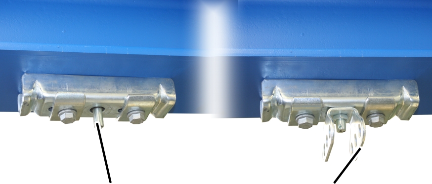
Requirements for the specialist welding company
The firm contracting the specialist welding company is responsible for the selection and the proper qualifications of the welding company.
Before the welding work can be carried out:
- A welding supervisor (e.g. of a specialist welding company) must create a set of instructions for the welding work.
- These welding instructions are used by specialist welding staff as the basis for all welding work.
- In Europe: the welding supervisor and welding company must have a certification according to DIN EN 1090 EXC-3.
Welding on the weld-on block
On every ceiling-mounted bracket 2LP/M16 or M20:
The specified dimensions, positions and clearances must be followed exactly.
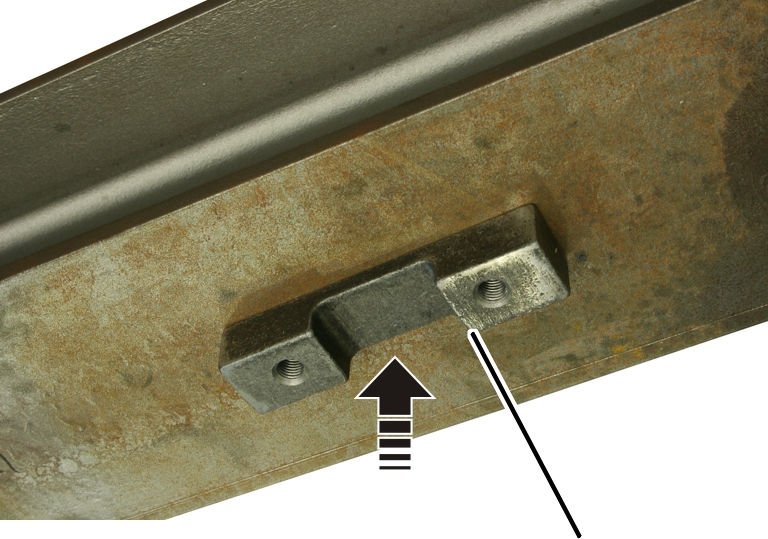
- Clean the welding point.
No rust, scale, ink, grease or oil should be present in the area of the weld.
Ceiling-mounted bracket centred in relation to HB profile railCeiling-mounted bracket perpendicular to HB profile rail
- Align the weld-on block so that it is lengthwise exactly perpendicular to the later-installed HB profile rail.
- Position the weld-on block so that it is exactly centred in relation to the later-installed HB profile rail.
This is necessary so that the HB profile rail can later be aligned.
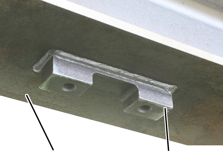
- Weld on the block with a circumferential fillet weld (a = 4 mm).
- Material of weld-on block: S 235 JR.
- Quality of weld seams: quality class B according to DIN EN ISO 5817.
- Paint the weld-on block and the entire supporting structure (or provide another means of protection against rust).
Bolting the ceiling-mounted bracket 2LP/M16 or M20 onto the weld-on block
Only with ceiling-mounted bracket 2LP/M16 with articulated girder
This section only applies to the ceiling-mounted bracket 2LP/M16 with bolted-on articulated girder (with normal stiffener, inclined suspension, inclined stiffener and V-suspension).
Turning the articulated girder
On every ceiling-mounted bracket 2LP/M16 with articulated girder:
The articulated girders can be mounted lengthwise or crosswise to the ceiling-mounted bracket 4LP/M20 as appropriate for the alignment of the supporting structure.
Ceiling-mounted bracket
- Insert M16x35 rib screw through articulated girder.
- Insert articulated girder with rib screw in ceiling-mounted bracket.
- Screw the M16 rib nut loosely onto the rib screw from the back.
- Shift the articulated girder lengthwise or crosswise to the ceiling-mounted bracket as necessary.
- Screw the rib nut on. Tighten to 300 Nm.
On every ceiling-mounted bracket 2LP/M16 or M20:
Ceiling-mounted bracketWeld-on block
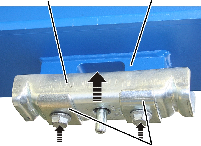
- Hold the ceiling-mounted bracket under the weld-on block.
- Insert clamping plates (2x) on M16x45 rib screws (2x).
- Screw in rib screws with clamping plates.
- Tighten the rib screws to 200 Nm.
Installing the ceiling-mounted bracket 2LP/M16 or M20: Dowel plate
The ceiling-mounted bracket 2LP/M16 or M20 is bolted to a dowel plate, which in turn is dowelled with anchor rods to a concrete ceiling.
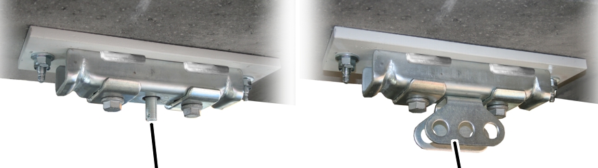
Positioning the dowel plate
On every dowel plate:
The specified dimensions, positions and clearances must be followed exactly.
First, only one of the holes is drilled, the anchor rod is fixed within it and, after the injection mortar hardens, the dowel plate is bolted on. The other drilled holes are only drilled afterwards through the hole in the tightly bolted-on dowel plate. Otherwise the drilled holes could go astray during the drilling and no longer align.
Ceiling-mounted bracket centred in relation to HB profile railCeiling-mounted bracket perpendicular to HB profile rail
- Position the dowel plate as specified in the planning documents.
- Align the dowel plate so that it is lengthwise exactly perpendicular to the later-installed HB profile rail.
- Position the dowel plate so that it is exactly centred in relation to the later-installed HB profile rail.
This is necessary so that the HB profile rail can later be aligned.
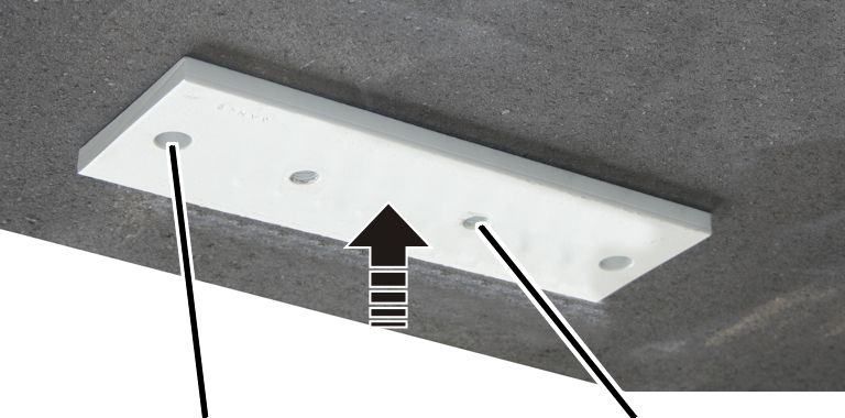
- Thoroughly sweep and clean the entire assembly area.
- Mark a hole of the dowel plate on the supporting structure.
Depending on the load capacity, the dowel plate as two or four holes.
Drilling holes
On a hole of the dowel plate:
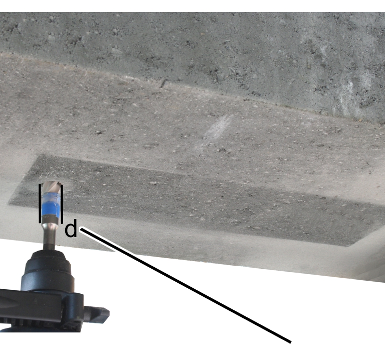
- Clamp the carbide masonry drill bit with the correct diameter in the hammer drill.
Only use drill bits that bear the inspection mark of the appropriate testing authority (in Germany: Remscheid).
Anchor rod |
Borehole diameter d |
|---|---|
M12 |
14 mm |
M16 |
18 mm |
Only with pre-fabricated or cast concrete elements
This section only applies if the HB crane installation is to be dowelled to pre-fabricated, fully cast or other concrete elements.
Concrete cover
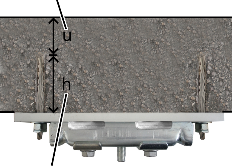
- Observe the drilled hole depth from the lower edge of the supporting structure and concrete cover, and hold the hammer drill exactly vertical.
All dimensions for the dowelled anchor rods such as drilled hole depths, edge clearances etc. are specified in the planning documents. These specifications must be followed exactly.
Anchor rod |
Drilled hole depth from lower edge of supporting structure h |
Concrete cover (drilled hole base to top edge of concrete ceiling) |
|---|---|---|
M12 |
105 mm |
25 mm |
M16 |
130 mm |
30 mm |
- Drill holes.
- Check the depth of the drilled holes with a measuring instrument.
Only with composite decks
This section only applies if the anchor rod is to be dowelled in composite decks (e.g. filigree deck slabs).
Concrete coverDrilled hole depth, in-situ concrete
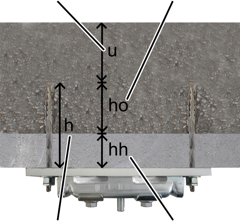
The semi-precast element of a composite deck cannot absorb any dynamic loads and is thus unable to transfer the stress through the HB crane to the building. Only the in-situ concrete of a composite deck can absorb dynamic loads.
The anchor rod must therefore be fully anchored in the in-situ concrete for “Drilled hole depth, in-situ concrete”.
- Observe the drilled hole depth in the in-situ concrete and concrete cover.
All dimensions for the dowelled anchor rods such as drilled hole depths, edge clearances etc. are specified in the planning documents. These specifications must be followed exactly.
Anchor rod |
Drilled hole depth, in-situ concrete (ho) |
Concrete cover (drilled hole base to top edge of concrete ceiling (u)) |
|---|---|---|
M12 |
105 mm |
25 mm |
M16 |
130 mm |
30 mm |
- Add the thickness of the semi-precast element to the drilled hole depth of the in-situ concrete.
Total drilled hole depth = Drilled hole depth in in-situ concrete + thickness of semi-precast element
The semi-precast element must not exceed a maximum thickness of 70 mm.
To compensate for the additional thickness of the non-load-bearing semi-precast element, anchor rods with a greater overall length are supplied for composite decks.
- Hold the hammer drill exactly vertical and drill the hole.
- Check the depth of the drilled holes with a measuring instrument.
Cleaning the drilled hole
At the drilled hole:
Drilled hole
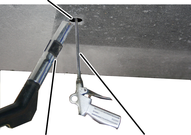
- Blow out the drilled holes from the base of the hole at least twice with a blow-out pump or with oil-free compressed air and vacuum up the drill dust.
Drilled hole brush
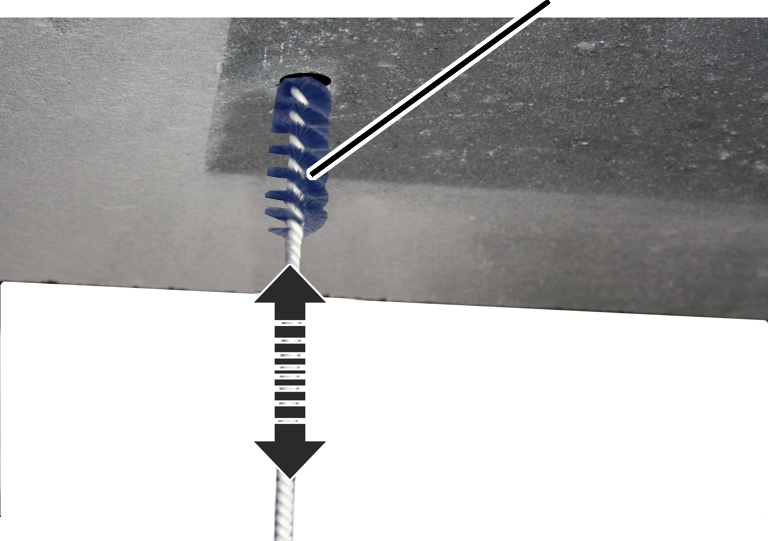
- Brush out the drilled holes twice with the drilled hole brush.
- Blow out the drilled holes and vacuum up the drill dust two more times.
Preparing the capsule
CapsuleStatic mixer
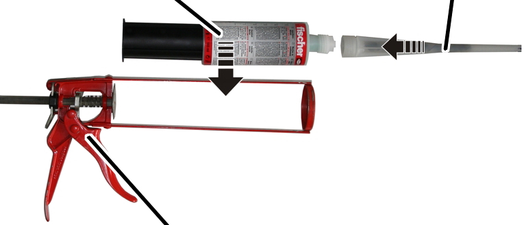
- Unscrew the capsule seal.
- Screw on the static mixer.
- Place the capsule in the pressure gun.
Tip of static mixerUnmixed injection mortar
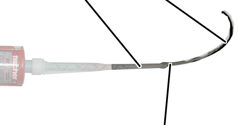
- Press injection mortar out of the capsule until the injection mortar emerging has been uniformly mixed and is clearly grey in colour. Do not use injection mortar that is not grey in colour.
- In the event of interruptions (e.g. between two dowel fittings), do not unscrew the static mixer from the capsule.
- After each interruption, squeeze out two gun strokes of unused injection mortar and do not use.
- After longer breaks, screw on a new static mixer and again squeeze out the injection mortar for as long as is needed until the discharged injection mortar is clearly grey in colour.
- Injection mortar which is not grey is not mixed correctly and will not set. Do not use any injection mortar which is not grey coloured!
- Setting time of the injection mortar:
Temperature of the capsule |
Setting time [min] |
|---|---|
5 °C |
15 min |
20 °C |
6 min |
+30 °C |
4 min |
Filling the drilled hole with injection mortar
Scale
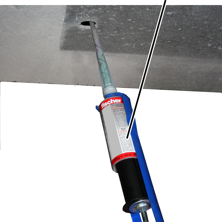
- Read off the necessary quantity of injection mortar from the table. From the base of the drilled hole, fill the drilled hole with injection mortar without any bubbles. Read off the quantity used to fill the hole from the scale on the capsule.
Drilled hole |
Quantity of injection mortar required |
|---|---|
M12 |
At least 8 scale units |
M16 |
At least 10 scale units |
- Continue immediately with the next work step (see “Inserting the anchor rod in the drilled hole”). Otherwise the injection mortar will harden and become unusable.
Inserting the anchor rod in the drilled hole
Discharged injection mortar
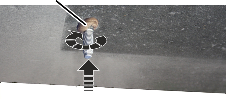
- Rotate the anchor rod slightly (without spherical washer and hexagonal nuts) and while doing so, press it into the drilled hole. Press the anchor rod in so far that the shaft with the cones is completely in the drilled hole exactly up to the start of the thread.
- In the process, some injection mortar will emerge from the drilled hole.
- Only with composite decks: since the anchor rod is only anchored in the in-situ concrete, but the semi-precast element still lies beneath the in-situ concrete, no injection mortar will emerge from the hole.
If no injection mortar comes out of the drilled hole:
- Pull the anchor rod immediately out of the drilled hole.
- Fill up the drilled hole with additional injection mortar.
- Insert the anchor rod again as described.
- Continue immediately with the next work step (see “Wiping injection mortar off”). Otherwise the injection mortar will harden and the dowel plate can no longer be fitted flat.
Wiping off injection mortar
- Wipe off the injection mortar that has come out of the hole.
Otherwise the dowel plate cannot be bolted flat under the concrete ceiling later.
Fitting the wedge
A wedge is now inserted to make sure the anchor rod is held safely in the drilled hole (e.g. while the first anchor rod is being installed on other dowel plates).
Wedge
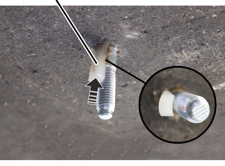
- Turn the wedge with the concave side towards the anchor rod and push it into the drilled hole.
- Push the wedge until the anchor rod is safely in the drilled hole and does not slip out.
- The anchor rod is pushed slightly to the side by this. This is not of any significance for further installation work.
Allowing the injection mortar to harden
- Allow the injection mortar to harden.
Temperature in concrete ceiling |
Hardening time [min] |
|---|---|
-5°C to 0°C |
360 min |
+1°C to +5°C |
180 min |
+6°C to +10°C |
90 min |
+11°C to +20°C |
35 min |
+21°C to +30°C |
20 min |
+31°C to +40°C |
12 min |
Tip:
The time during which the injection mortar is hardening can be used to install the first anchor rod on other dowel plates.
Screwing the dowel plate on
After the injection mortar has hardened around the first anchor rod:
Clamping bush
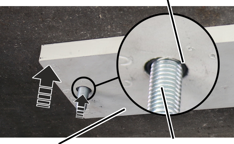
- Remove the projecting part of the wedge.
- Push the dowel plate with the hole without thread onto the installed anchor rod.
Do not use the holes with thread. The ceiling-mounted bracket is installed using these later.
- Align the dowel plate as described at the beginning.
- Place the clamping bush on the anchor rod.
- Push the assembly aid on the anchor rod.
- Knock in the clamping bush using a hammer and the assembly aid until the lower end of the clamping bush is flush with the lower edge of the dowel plate.
Spherical washerBall socket
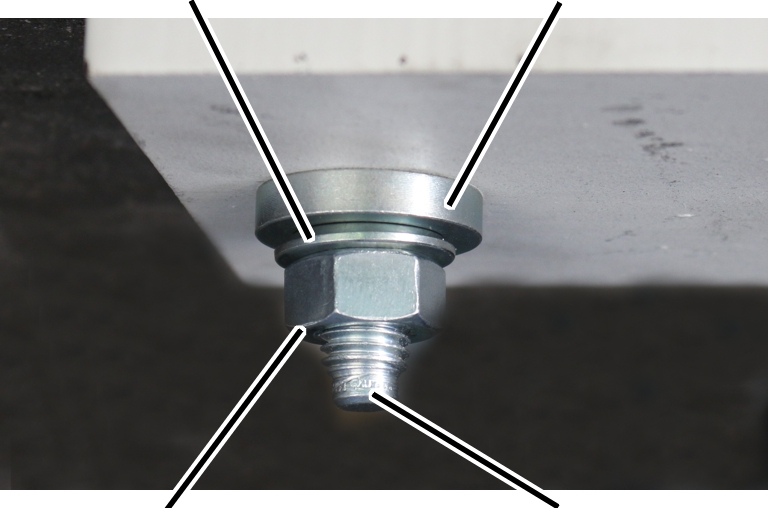
- Insert the ball socket on the anchor rod.
- Insert the spherical washer.
- Screw the M12 or M16 hexagonal nut to the anchor rod and tighten it carefully so that the dowel plate can no longer be twisted.
- The dowel plate is located firmly under the concrete ceiling and serves as a template for the other drilled holes.
Installing all additional anchor rods afterward
Then set all the other holes:
- Drill through the dowel plate into the concrete ceiling at all additional holes in the dowel plate (one or three additional holes).
The dowel plate serves here as a template.
- Clean the drilled holes, check the drilled holes, prepare the capsule, fill the drilled hole with injection mortar, screw the anchor rod into the drilled hole, wipe the injection mortar off, allow the injection mortar to harden and screw the dowel plate on as described above.
The wedge is only used for the first anchor rod.
Bolting dowel plate tight in final position
As soon as the injection mortar has hardened:
- Tighten all hexagonal nuts with the correct torque.
Anchor rod |
Tightening torque |
|---|---|
M12 |
40 Nm |
M16 |
60 Nm |
If the hexagonal nuts cannot be tightened with the necessary tightening torque (e.g. because the anchor rod turns with them), the anchor rod is not fitted correctly.
In this case:
- Do not continue installing the HB crane installation.
- Call ABUS for further instructions.
Securing and sealing the hexagonal nuts
On all anchor rods:
Lock nut
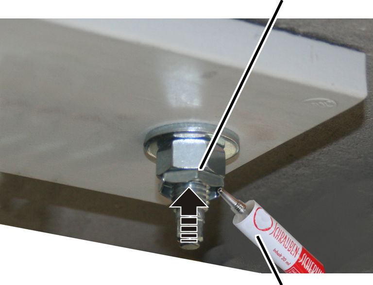
- Screw the lock nuts to the anchor rods. Screw until hand-tight.
- Seal the hexagonal nuts, lock nuts and anchor rods with screw lock lacquer.
Do not cut off protruding anchor rods:
Technical data is stamped on the heads of the anchor rods. This enables later identification of the anchor rods. For this reason, the protruding parts of the anchor rods should not be cut off.
Documenting the installation
- Glue or attach the labels with approval number, conformity symbol, batch number and EAN code of the anchor rods in the dowel protocol (see “Dowel protocol”).
- Complete the dowel protocol and add it to the crane test log book.
Screwing the ceiling-mounted bracket 2LP/M16 or M20 tight
Only with ceiling-mounted bracket 2LP/M16 with articulated girder
This section only applies to the ceiling-mounted bracket 2LP/M16 with bolted-on articulated girder (with normal stiffener, inclined suspension, inclined stiffener and V-suspension).
Turning the articulated girder
On every ceiling-mounted bracket 2LP/M16 with articulated girder:
The articulated girders can be mounted lengthwise or crosswise to the ceiling-mounted bracket 4LP/M20 as appropriate for the alignment of the supporting structure.
Ceiling-mounted bracket
- Insert M16x35 rib screw through articulated girder.
- Insert articulated girder with rib screw in ceiling-mounted bracket.
- Screw the M16 rib nut loosely onto the rib screw from the back.
- Shift the articulated girder lengthwise or crosswise to the ceiling-mounted bracket as necessary.
- Screw the rib nut on. Tighten to 300 Nm.
On every ceiling-mounted bracket 2LP/M16 or M20:
Ceiling-mounted bracketClamping plate
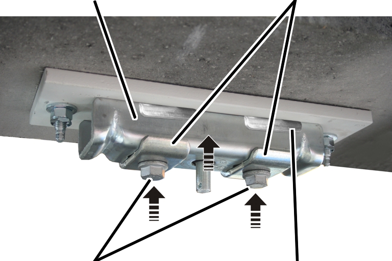
- Insert the M16x70 rib screws (2x) through the clamping plates (2x), ceiling-mounted bracket (1x) and retaining plates (2x).
- Hold the ceiling-mounted bracket under the dowel plate and loosely screw in the rib screws.
- First, screw in M16x70 rib screws (2x) until hand-tight.
The rib screws will later be tightened to the correct tightening torque (after aligning the HB profile rail).
If final alignment of the ceiling-mounted bracket 2LP/M16 or M20 can now be done:
- Tighten the rib screws to 200 Nm.
Dowel protocol
Order number |
|
|---|---|
Building project |
|
Installation company |
Nominal specifications |
Nominal specifications |
||
|---|---|---|---|
Dowels used for reinforced concrete ceiling |
FHB dyn |
FHB dyn |
❑ Description agrees |
Dowels used for composite deck |
FHB dyn |
FHB dyn |
❑ Description agrees |
Injection mortar used |
FIS HB 150 C |
FIS HB 150 C |
❑ Description agrees |
Number of mounted dowels |
_____ pieces |
||
Concrete strength according to DIN 1045 / DIN 1045-1 / EC2 |
≥ B25 |
≥ B25 |
According to customer specifications B _____ C _____ |
Load-bearing thickness of the base plate |
140 mm |
160 mm |
According to customer specifications _____ mm |
Drilled hole depth h |
≥ 105 mm |
≥ 130 mm |
_____ mm |
Drilled hole nominal diameter d |
14 mm |
18 mm |
_____ mm |
Drill cutting diameter |
14.0 to 14.5 mm |
18.0 to 18.5 mm |
_____ mm |
The hammer drill used bears the test symbol issued by the German test association for masonry drills (e.V. Remscheid) |
❑ yes |
||
Cleaning the drilled holes |
Blow out 2x Brush out 2x Blow out 2x |
Blow out 2x Brush out 2x Blow out 2x |
___ blown out ___ brushed out ___ blown out |
Temperature in the anchor base |
-5°C to 40°C |
-5°C to 40°C |
_____ °C |
Distance from drilled holes to edge or joints of concrete component |
150 mm |
150 mm |
_____ mm |
Tightening torque |
40 Nm |
60 Nm |
_____ Nm |
Were the hexagonal nuts tightened with a tested and calibrated torque wrench? |
❑ yes |
||
Are all the hexagonal nuts secured with lock nuts? |
❑ yes |
||
Are all the dowels sealed with sealing wax? |
❑ yes |
||
Was the dowel installation carried out properly according to this product manual and this protocol completed in full? |
❑ yes |
||
_____________ _____________ __________________________ __________________________
Place Date Name in block letters Signature
Installing the ceiling-mounted bracket 2LP/M16 or M20: Anchor connection on concrete element
The ceiling-mounted bracket 2LP/M16 or M20 is bolted onto two cup square bolts. The cup square bolts are inserted through holes in a concrete element and secured on the other side with counter plates.
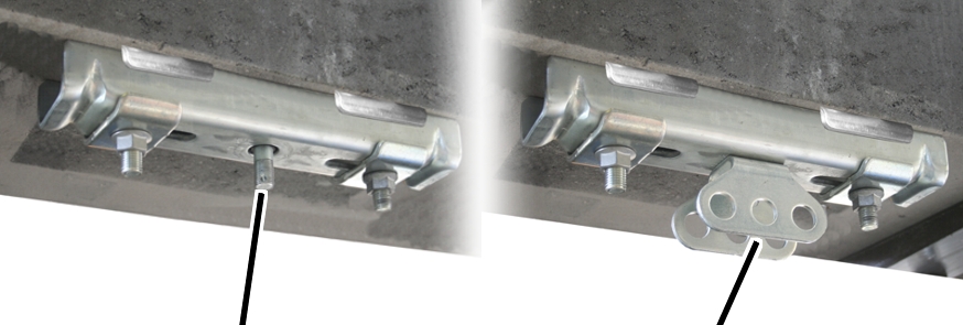
Drilling the thru-holes
On every ceiling-mounted bracket 2LP/M16 or M20:
The specified dimensions, positions and clearances must be followed exactly.
Ceiling-mounted bracket centred in relation to HB profile railCeiling-mounted bracket perpendicular to HB profile rail
- Position the drilled holes so that the ceiling-mounted bracket will later be lengthwise exactly perpendicular to the later-installed HB profile rail.
- Position the drilled holes so that the ceiling-mounted bracket will later be exactly centred in relation to the later-installed HB profile rail.
This is necessary so that the HB profile rail can later be aligned.
Drilled hole spacingDrilled hole diameter
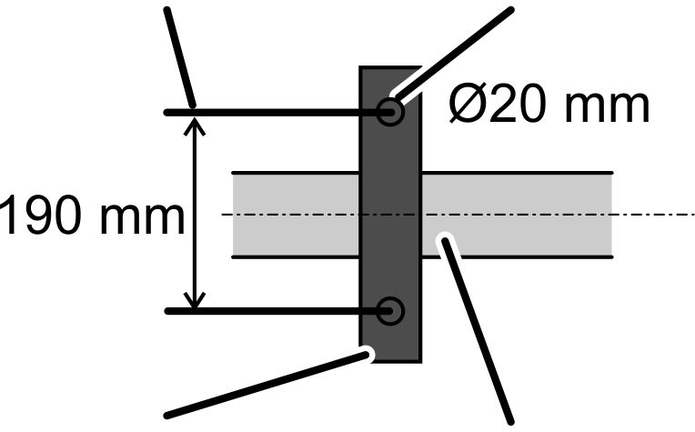
- On the other side of the concrete element, press a wooden beam (for example) against the exit point of the drill. This ensures the concrete element does not crumble as much during the drilling.
- Observe occupational safety regulations and use a suitable impact drill (appropriate for the material of the concrete element) to drill two thru-holes in the concrete element:
- Drilled hole diameter: 20 mm
- Drilled hole spacing: 190 mm
Inserting cup square bolts into the concrete element
On every ceiling-mounted bracket 2LP/M16 or M20:
Counter plateCup square bolts
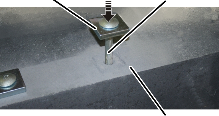
- Insert cup square bolts (2x) with counter plate (1x each) through the concrete element from above.
Screwing the ceiling-mounted bracket 2LP/M16 or M20 tight
Only with ceiling-mounted bracket 2LP/M16 with articulated girder
This section only applies to the ceiling-mounted bracket 2LP/M16 with bolted-on articulated girder (with normal stiffener, inclined suspension, inclined stiffener and V-suspension).
Turning the articulated girder
On every ceiling-mounted bracket 2LP/M16 with articulated girder:
The articulated girders can be mounted lengthwise or crosswise to the ceiling-mounted bracket 4LP/M20 as appropriate for the alignment of the supporting structure.
Ceiling-mounted bracket
- Insert M16x35 rib screw through articulated girder.
- Insert articulated girder with rib screw in ceiling-mounted bracket.
- Screw the M16 rib nut loosely onto the rib screw from the back.
- Shift the articulated girder lengthwise or crosswise to the ceiling-mounted bracket as necessary.
- Screw the rib nut on. Tighten to 300 Nm.
On every ceiling-mounted bracket 2LP/M16 or M20:
Retaining platesCup square bolt
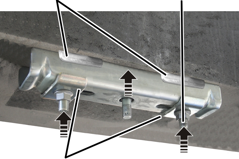
- Insert retaining plates (2x), ceiling-mounted bracket (1x) and clamping plates (2x) on the cup square bolt from below.
- Loosely screw on the ceiling-mounted bracket with the M16 rib nuts (2x).
- Position the ceiling-mounted bracket so that it is exactly centred in relation to the later-installed HB profile rail.
This is necessary so that the HB profile rail can later be aligned far enough to the left or right. The ceiling-mounted bracket can later be shifted 12 mm to the left or right.
- Screw on the M16 rib nuts (2x) initially hand-tight.
The rib nuts will later be tightened to the correct tightening torque (after aligning the HB profile rail).
If final alignment of the ceiling-mounted bracket 2LP/M16 or M20 can now be done:
- Screw the rib nuts tight to 90 Nm.
Installing the ceiling-mounted bracket 2LP/M16: anchor bar (Halfen channel)
The ceiling-mounted bracket 2LP/M16 is bolted onto an anchor bar made by the Halfen company, which has been firmly cast in the concrete element.
Only one 2LP/M16 ceiling-mounted bracket can be installed on a cast anchor rod on a ceiling connection. A 2LP/M20 or 4LP/M20 ceiling-mounted bracket cannot be installed.
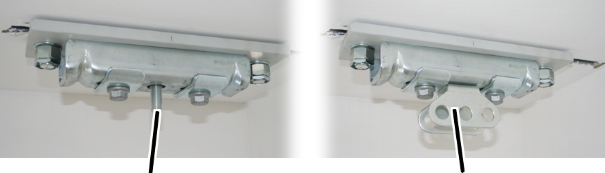
Casting the Halfen channel in the concrete element
When casting the concrete element:
The specified dimensions, positions and clearances must be followed exactly.
- Only use anchor bars manufactured by the Halfen company that have been approved by building inspectors and are suitable for dynamic loads.
- Follow the instructions of the manufacturer.
- Only use parts of the Halfen channel system that are designed for one another.
Ceiling-mounted bracket centred in relation to HB profile railCeiling-mounted bracket perpendicular to HB profile rail
- Align the Halfen channel so that the ceiling-mounted bracket will later be lengthwise exactly perpendicular to the later-installed HB profile rail.
- Position the Halfen channel so that the ceiling-mounted bracket will later be exactly centred in relation to the later-installed HB profile rail.
This is necessary so that the HB profile rail can later be aligned.
- Take the Halfen channel into account when planning the reinforcement and concrete covering.
Installing the threaded plate
On every ceiling-mounted bracket 2LP/M16:
Halfen channel
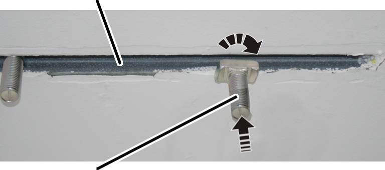
- Insert the Halfen screws (2x) in the Halfen channel while turning them.
- Position the Halfen screws so that they fit the hole spacing of the threaded plate.
Threaded plateSquare washer
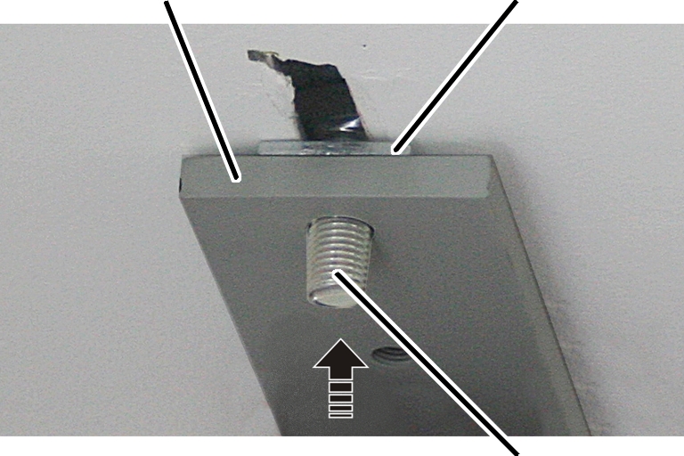
- Insert square washers (2x) on the Halfen screws.
The threaded plate must lie flat against the Halfen channel. It should not lie on the concrete around the Halfen channel. The square washer ensures that the threaded plate lies against the Halfen channel and does not strain the concrete.
- Insert the threaded plate on the Halfen screws.
Washer
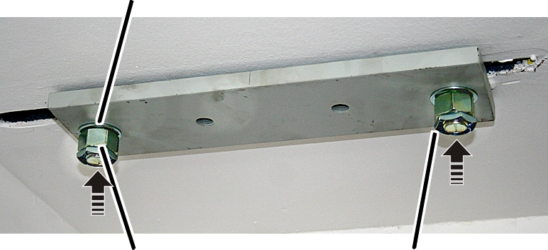
- Screw on washers (2x) and hexagonal nuts (2x) on the Halfen channel.
- Screw on hexagonal nut.
Halfen screw |
Size, length and rating |
Tightening torque |
|---|---|---|
HSR40/22 |
M16x40 (8.8) |
200 Nm |
HSR 50/30 |
M20x45 (8.8) |
400 Nm |
HS 50/30 |
M24x45 (4.6) |
200 Nm |
HS 72/48 |
M24x45 (8.8) |
680 Nm |
- Screw on lock nuts (2x) and counter them.
Bolting the ceiling-mounted bracket 2LP/M16 to the threaded plate
Only with ceiling-mounted bracket 2LP/M16 with articulated girder
This section only applies to the ceiling-mounted bracket 2LP/M16 with bolted-on articulated girder (with normal stiffener, inclined suspension, inclined stiffener and V-suspension).
Turning the articulated girder
On every ceiling-mounted bracket 2LP/M16 with articulated girder:
The articulated girders can be mounted lengthwise or crosswise to the ceiling-mounted bracket 4LP/M20 as appropriate for the alignment of the supporting structure.
Ceiling-mounted bracket
- Insert M16x35 rib screw through articulated girder.
- Insert articulated girder with rib screw in ceiling-mounted bracket.
- Screw the M16 rib nut loosely onto the rib screw from the back.
- Shift the articulated girder lengthwise or crosswise to the ceiling-mounted bracket as necessary.
- Screw the rib nut on. Tighten to 300 Nm.
On every ceiling-mounted bracket 2LP/M16:
Clamping plate
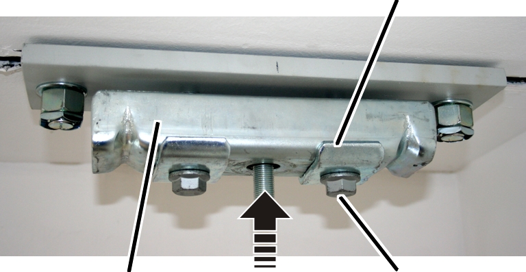
- Hold the ceiling-mounted bracket (1x) and the clamping plates (2x) against the threaded plate from below.
- Loosely screw on the ceiling-mounted bracket with the M16x70 rib screws (2x).
- Position the ceiling-mounted bracket so that it is exactly centred in relation to the later-installed HB profile rail.
This is necessary so that the HB profile rail can later be aligned.
- First, screw in M16x70 rib screws (2x) until hand-tight.
The rib screws will later be tightened to the correct tightening torque (after aligning the HB profile rail).
If final alignment of the ceiling-mounted bracket 2LP/M16 can now be done:
- Tighten the rib screws to 200 Nm.
Installing the ceiling-mounted bracket 2LP/M16 or M20: clasping the wooden beam
The ceiling-mounted bracket 2LP/M16 or M20 is bolted with a second ceiling-mounted bracket on the opposite side of a wooden beam as a means of clasping it.
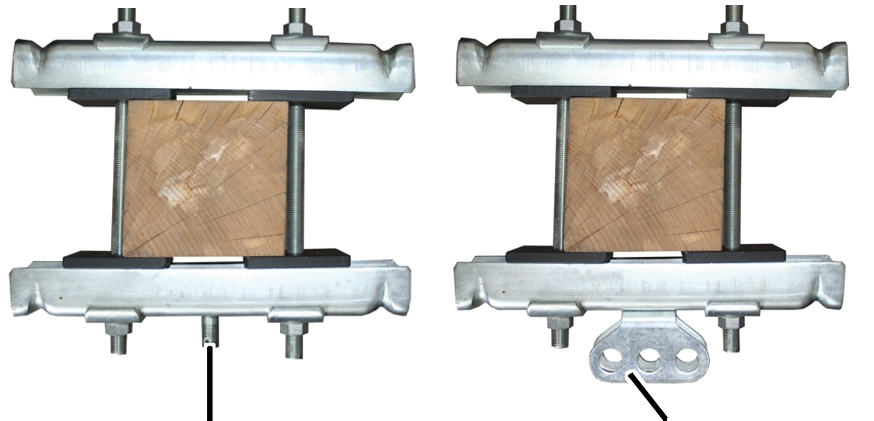
Sawing the threaded rods
- Measure the thickness of the wooden beam.
- Saw the threaded rods:
Length = 2 x 80 + beam thickness
Each suspension requires two threaded rods.
Only with ceiling-mounted bracket 2LP/M16 with articulated girder
This section only applies to the ceiling-mounted bracket 2LP/M16 with bolted-on articulated girder (with normal stiffener, inclined suspension, inclined stiffener and V-suspension).
Turning the articulated girder
On every ceiling-mounted bracket 2LP/M16 with articulated girder:
The articulated girders can be mounted lengthwise or crosswise to the ceiling-mounted bracket 4LP/M20 as appropriate for the alignment of the supporting structure.
Ceiling-mounted bracket
- Insert M16x35 rib screw through articulated girder.
- Insert articulated girder with rib screw in ceiling-mounted bracket.
- Screw the M16 rib nut loosely onto the rib screw from the back.
- Shift the articulated girder lengthwise or crosswise to the ceiling-mounted bracket as necessary.
- Screw the rib nut on. Tighten to 300 Nm.
Installing the ceiling-mounted bracket 2LP/M16 or M20 on the wooden beam
On each ceiling-mounted bracket above the wooden beam on both sides:
The specified dimensions, positions and clearances must be followed exactly.
Clamping plateCeiling-mounted bracket, opposite side
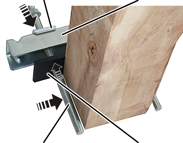
- Insert the clamping plate on the threaded rod.
- Screw an M16 rib nut onto the threaded rod from above.
- Insert the threaded rod with clamping plate through the upper ceiling-mounted bracket.
- Insert the intermediate plate on the threaded rod from below.
- Lay the ceiling-mounted bracket on the wooden beam from above.
- Push the threaded rods from both sides up to the wooden beam.
The threaded rods should lie close against the wooden beam.
Ceiling-mounted bracket centred in relation to HB profile railCeiling-mounted bracket perpendicular to HB profile rail
- Align the ceiling-mounted bracket so that it lies lengthwise exactly perpendicular to the later-installed HB profile rail.
- Position the ceiling-mounted bracket so that it is exactly centred in relation to the later-installed HB profile rail.
This is necessary so that the HB profile rail can later be aligned.
Under the wooden beam:
Intermediate plateRib nut
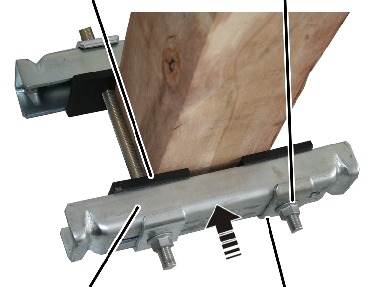
- Insert the intermediate plates (2x) on the threaded rods.
- Insert the ceiling-mounted bracket on the threaded rods.
- Insert the clamping plates (2x) on the threaded rods.
- Screw on the M16 rib nuts (2x) initially hand-tight.
The rib nuts will later be tightened to the correct tightening torque (after aligning the HB profile rail).
If final alignment of the ceiling-mounted bracket 2LP/M16 or M20 can now be done:
- Screw the rib nuts tight to 90 Nm.
Installing the ceiling-mounted bracket 2LP/M16 or M20: bolting on with rib nuts
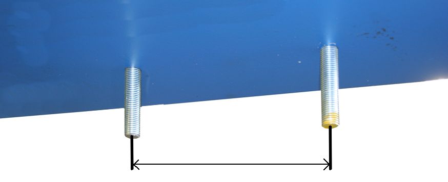
The ceiling-mounted bracket 2LP/M16 or M20 is bolted onto its own fastener (customer provided). For this, a pair of M16x70 threaded rods must be available at the site.
Ceiling-mounted bracket 2LP/M16 or M20 |
Minimum spacing of threaded rods |
Maximum spacing of threaded rods |
|---|---|---|
Ceiling-mounted bracket A |
90 mm |
140 mm |
Ceiling-mounted bracket B |
140 mm |
240 mm |
Ceiling-mounted bracket C |
240 mm |
330 mm |
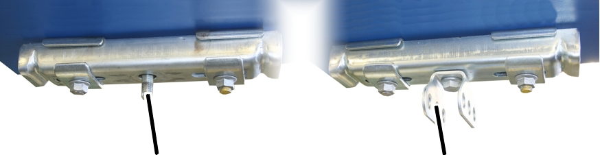
Bolting on the ceiling-mounted bracket 2LP/M16 or M20 with rib nuts
Only with ceiling-mounted bracket 2LP/M16 with articulated girder
This section only applies to the ceiling-mounted bracket 2LP/M16 with bolted-on articulated girder (with normal stiffener, inclined suspension, inclined stiffener and V-suspension).
Turning the articulated girder
On every ceiling-mounted bracket 2LP/M16 with articulated girder:
The articulated girders can be mounted lengthwise or crosswise to the ceiling-mounted bracket 4LP/M20 as appropriate for the alignment of the supporting structure.
Ceiling-mounted bracket
- Insert M16x35 rib screw through articulated girder.
- Insert articulated girder with rib screw in ceiling-mounted bracket.
- Screw the M16 rib nut loosely onto the rib screw from the back.
- Shift the articulated girder lengthwise or crosswise to the ceiling-mounted bracket as necessary.
- Screw the rib nut on. Tighten to 300 Nm.
On every ceiling-mounted bracket 2LP/M16 or M20:
The specified dimensions, positions and clearances must be followed exactly.
Retaining plates
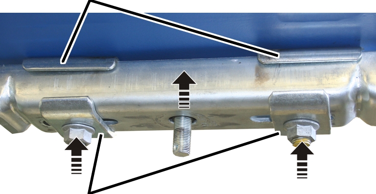
- Insert retaining plates (2x), ceiling-mounted bracket (1x) and clamping plates (2x) on the threaded rods.
- Loosely screw the M16 rib nuts (2x) onto the threaded rods.
Ceiling-mounted bracket centred in relation to HB profile railCeiling-mounted bracket perpendicular to HB profile rail
- Align the ceiling-mounted bracket so that it lies lengthwise exactly perpendicular to the later-installed HB profile rail.
- Position the ceiling-mounted bracket so that it is exactly centred in relation to the later-installed HB profile rail.
This is necessary so that the HB profile rail can later be aligned.
- Screw on the M16 rib nuts (2x) initially hand-tight.
The rib nuts will later be tightened to the correct tightening torque (after aligning the HB profile rail).
If final alignment of the ceiling-mounted bracket 2LP/M16 or M20 can now be done:
- Screw the rib nuts tight.
The correct tightening torque depends on the bolt quality and the friction coefficient from the standards table.
Example: 200 Nm for M16, bolt quality grade 8.8 and friction coefficient 0.12.
Installing the ceiling-mounted bracket 2LP/M16 or M20: bolting on with rib screw
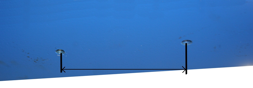
The ceiling-mounted bracket 2LP/M16 or M20 is bolted onto its own fastener (customer provided). For this, M16 threaded holes or thru-holes must be available at the site.
Material thickness |
Material quality |
|
|---|---|---|
Thru-holes and rib nuts |
Maximally 28 mm |
At least S235 |
Threaded hole and rib screw |
At least 16 mm |
At least S235 |
Ceiling-mounted bracket 2LP/M16 or M20 |
Minimum spacing of boreholes |
Maximum spacing of boreholes |
|---|---|---|
Ceiling-mounted bracket A |
90 mm |
140 mm |
Ceiling-mounted bracket B |
140 mm |
240 mm |
Ceiling-mounted bracket C |
240 mm |
330 mm |
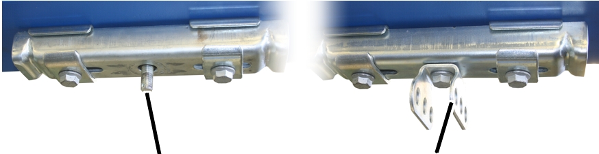
Bolting on the ceiling-mounted bracket 2LP/M16 oder M20 with rib screws
Only with ceiling-mounted bracket 2LP/M16 with articulated girder
This section only applies to the ceiling-mounted bracket 2LP/M16 with bolted-on articulated girder (with normal stiffener, inclined suspension, inclined stiffener and V-suspension).
Turning the articulated girder
On every ceiling-mounted bracket 2LP/M16 with articulated girder:
The articulated girders can be mounted lengthwise or crosswise to the ceiling-mounted bracket 4LP/M20 as appropriate for the alignment of the supporting structure.
Ceiling-mounted bracket
- Insert M16x35 rib screw through articulated girder.
- Insert articulated girder with rib screw in ceiling-mounted bracket.
- Screw the M16 rib nut loosely onto the rib screw from the back.
- Shift the articulated girder lengthwise or crosswise to the ceiling-mounted bracket as necessary.
- Screw the rib nut on. 300 Nm.
On every ceiling-mounted bracket 2LP/M16 or M20:
The specified dimensions, positions and clearances must be followed exactly.
Retaining plates
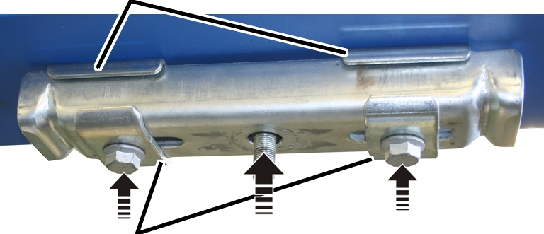
- Insert the rib screws (2x) through the clamping plates (2x), ceiling-mounted bracket (1x) and retaining plates (2x).
Rib screw |
|
|---|---|
Thru-holes and rib nuts |
M16x90 |
Threaded hole and rib screw |
M16x70 |
- Hold the ceiling-mounted bracket under the holes and loosely screw in the rib screws.
Ceiling-mounted bracket centred in relation to HB profile railCeiling-mounted bracket perpendicular to HB profile rail
- Align the ceiling-mounted bracket so that it lies lengthwise exactly perpendicular to the later-installed HB profile rail.
- Position the ceiling-mounted bracket so that it is exactly centred in relation to the later-installed HB profile rail.
This is necessary so that the HB profile rail can later be aligned.
- Screw in the rib screws (2x) initially hand-tight.
The rib screws will later be tightened to the correct tightening torque (after aligning the HB profile rail).
If final alignment of the ceiling-mounted bracket 2LP/M16 or M20 can now be done:
- Screw in the rib screws.
The correct tightening torque depends on the bolt quality and the friction coefficient from the standards table.
Example: 200 Nm for M16, bolt quality grade 8.8 and friction coefficient 0.12.
Installing an additional ceiling-mounted bracket 2LP/M16 (for stiffener or V-suspension)
Only with normal stiffener, inclined stiffener and V-suspension
This section only applies if an additional stiffener will be used (normal stiffener or inclined stiffener), or if a V-suspension will be used.
The specified dimensions, positions and clearances must be followed exactly.
Installing an additional ceiling-mounted bracket 2LP/M16
Additional ceiling-mounted bracket 2LP/M16
(for stiffener or V-suspension)
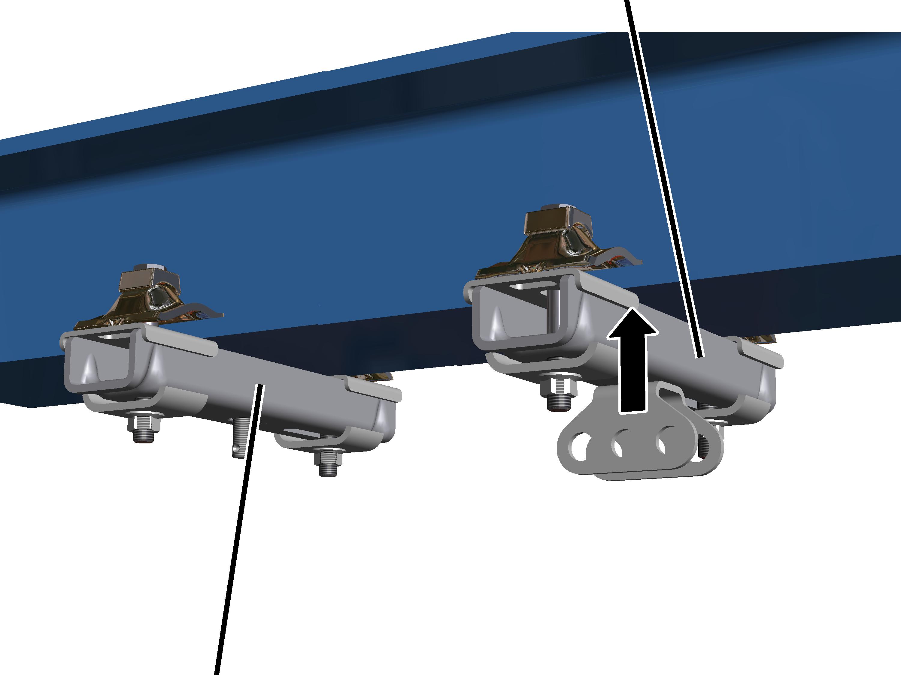
- Install the additional ceiling-mounted bracket with articulated girder next to the already existing ceiling-mounted bracket.
The specified dimensions, positions and clearances must be followed exactly.
Shortening or lengthening threaded rods
Threaded rods are required for all suspensions (except short suspensions) on which the crane track will later be suspended.
The threaded rods must be individually shortened or lengthened.
Shortening threaded rods:
- Shorten the threaded rod to the required length.
- Deburr the sawed edge.
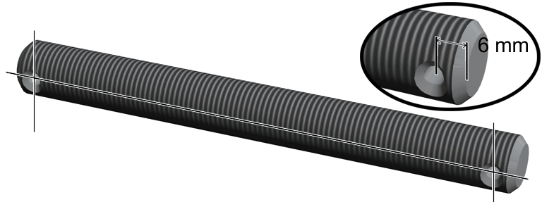
- Mark a new hole for the spring cotter 6 mm away from the sawed edge.
If the HB crane runway is suspended parallel or at a right angle to the ceiling-mounted bracket: the new hole must be exactly aligned to the existing hole at the other end of the threaded rod.
If the HB crane runway is suspended in a different angle to the ceiling-mounted bracket: the new hole must lie exactly in the required angle at the other end of the threaded rod.
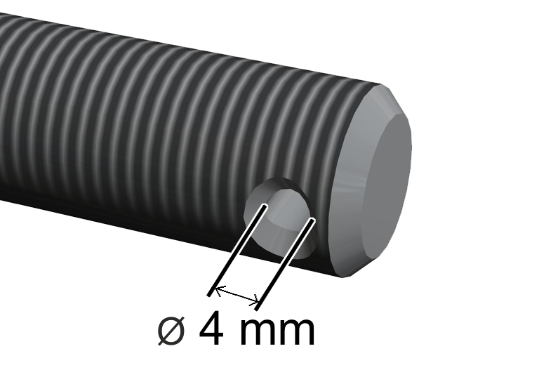
- Drill a hole (diameter 4 mm) in the threaded rod at the marked spot.
If necessary, (e.g. to compensate for inaccuracies), the hole in the threaded rod can be drilled with a diameter of 5 mm.
Lengthening threaded rods:
Coupling
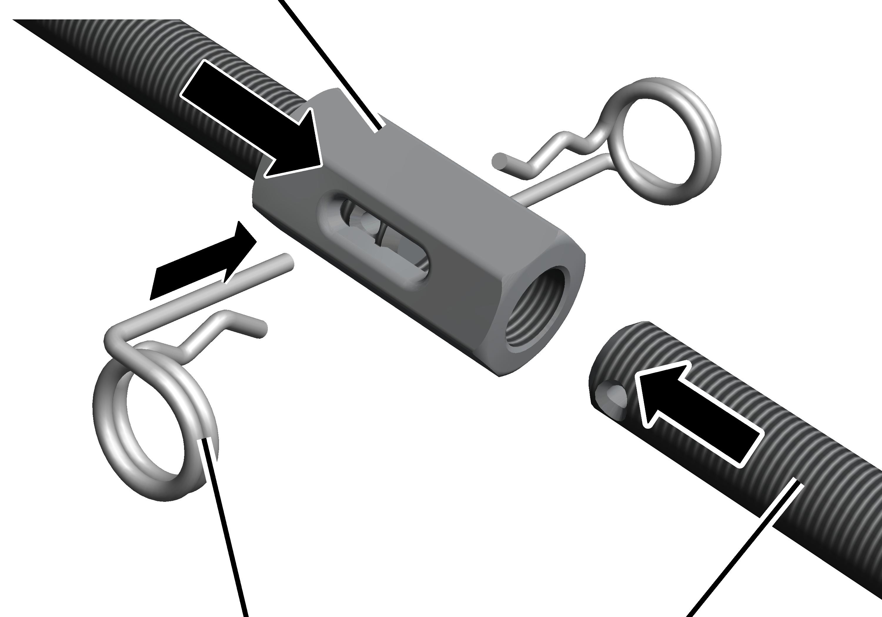
- Screw the coupling (both sides with right-hand thread) on the threaded rods.
- Screw the second threaded rod in the coupling.
- Turn the coupling so that the borehole is visible.
- Insert spring cotters (2x).
Craneway suspension M16: installing a normal suspension
The threaded rods from which the crane track will later be hung are now fitted on the installed ceiling-mounted bracket.
Overview:
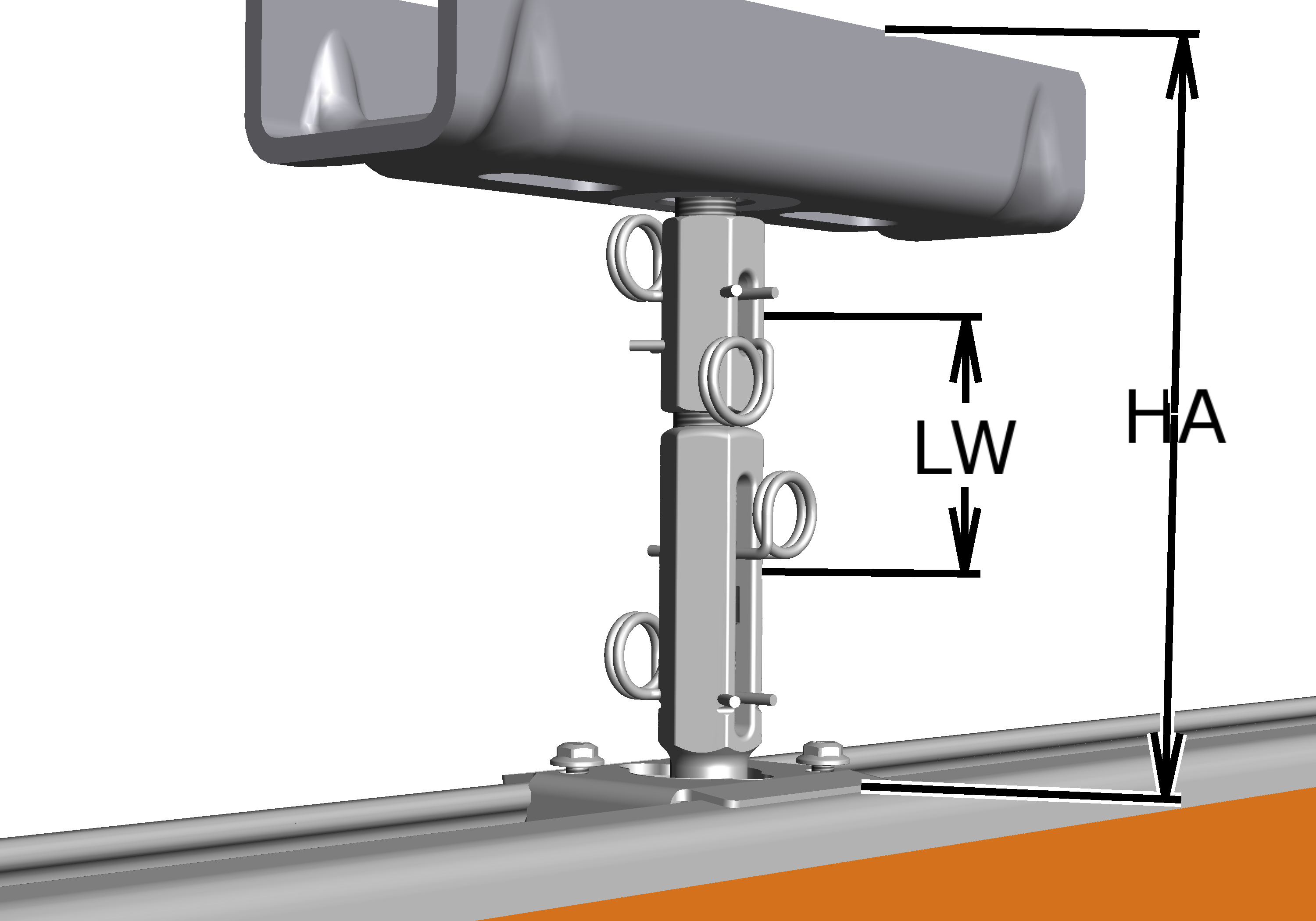
Size |
HA |
|---|---|
HB110 |
HA = LW ± 25 mm |
HB150 |
HA = LW ± 28 mm |
HB190 |
HA = LW ± 28 mm |
HB240 |
HA = LW ± 28 mm |
Installing the threaded rod on the ceiling-mounted bracket
On the ceiling-mounted bracket:
Cross-drilled holeSpring cotter
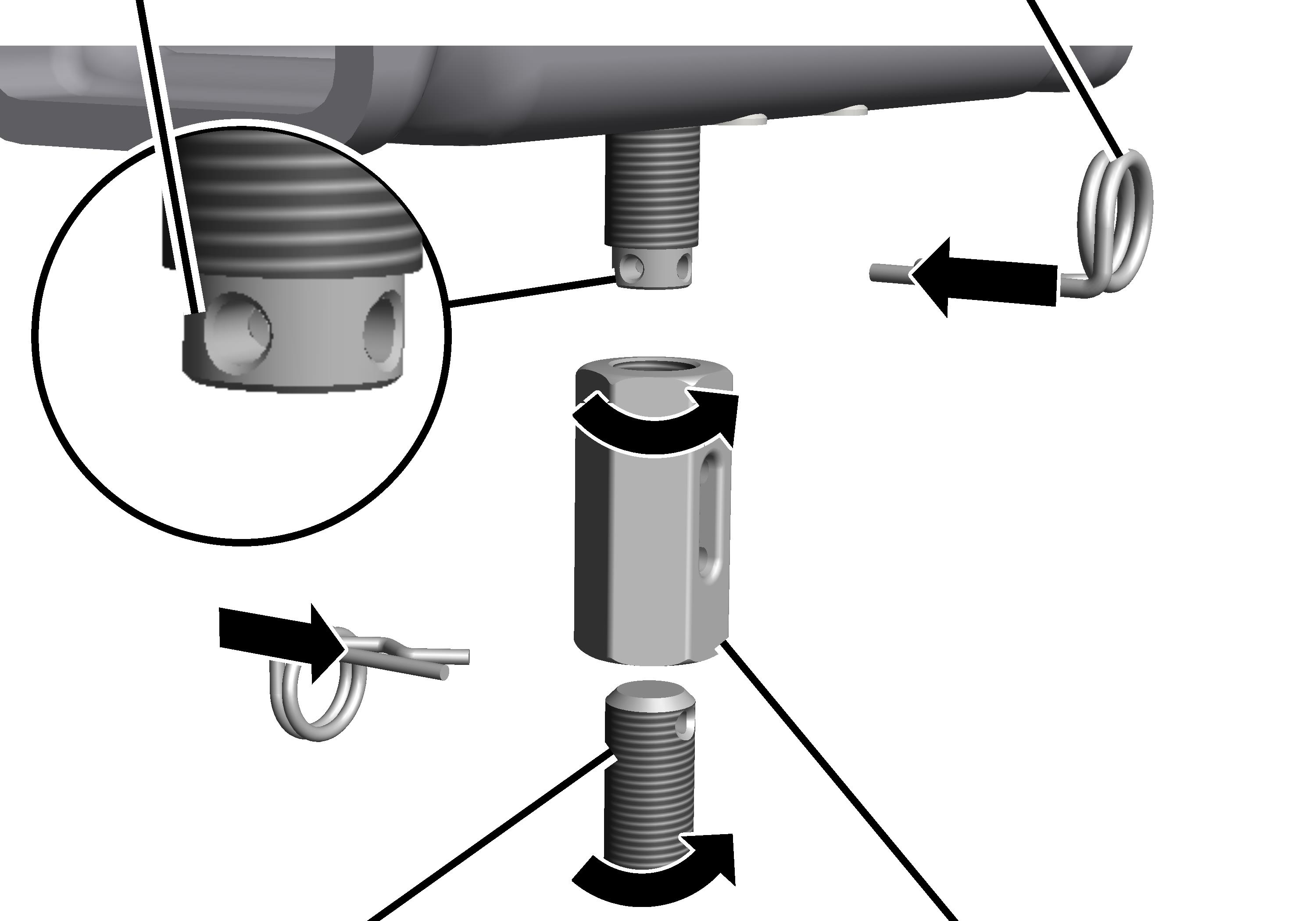
- Screw the coupling (both sides with right-hand thread) on the ceiling-mounted bracket.
- Screw the shortened or lengthened threaded rods in the coupling.
- Turn the coupling so that the boreholes are visible.
The threaded rod has a cross-drilled hole on the ceiling-mounted bracket. Turn the coupling in such a way that the hole facing across the later HB crane runway is used.
- Insert spring cotters (2x).
The HB crane runway will later be installed on the lower end of the threaded rod.
Craneway suspension M16: Installing a short suspension
The tension nuts from which the crane track will later be directly hung are now fitted on the installed ceiling-mounted bracket.
The short suspension is used for especially short clearances between ceiling-mounted bracket and crane track.
Overview of short suspension XS and S:
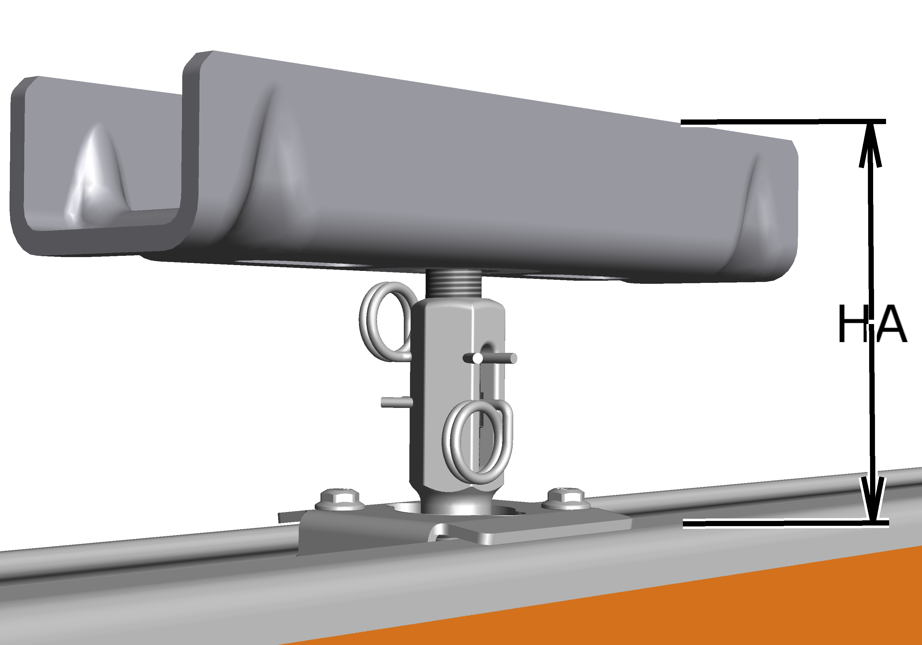
Overview of short suspension M and L:
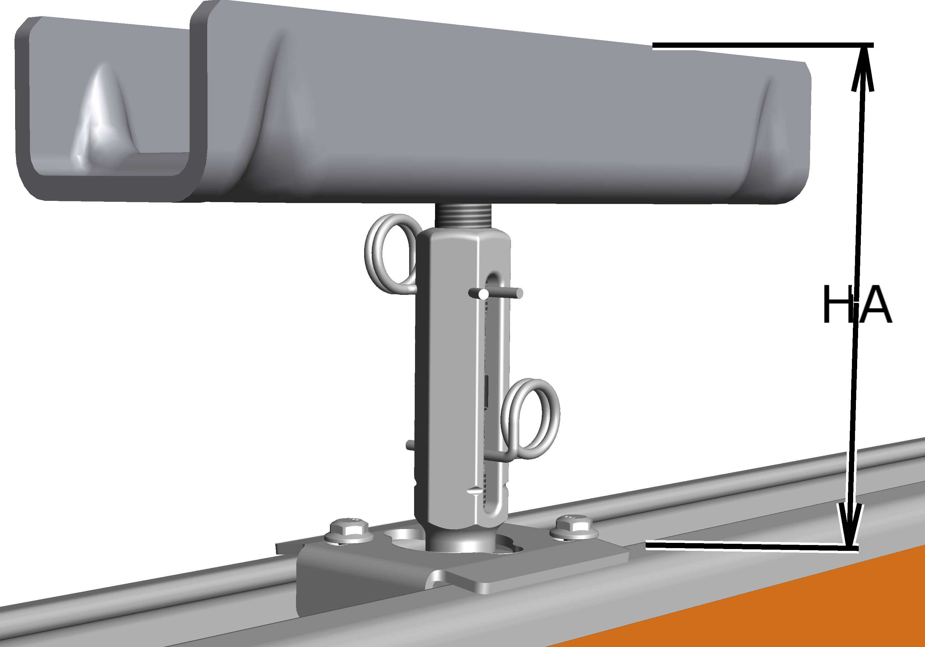
Size |
HA with short suspension XS |
HA with short suspension S |
HA with short suspension M |
HA with short suspension L |
|---|---|---|---|---|
HB110 |
105 to 125 mm |
125 to 145 mm |
135 to 175 mm |
155 to 195 mm |
HB150 |
102 to 124 mm |
122 to 144 mm |
132 to 174 mm |
142 to 194 mm |
HB190 |
102 to 124 mm |
122 to 144 mm |
132 to 174 mm |
142 to 194 mm |
HB240 |
102 to 124 mm |
122 to 144 mm |
132 to 174 mm |
142 to 194 mm |
Only for short suspension and ceiling-mounted brackets 2LP/M16 or M20 with flange clamps over a profile joint
This section only applies if a short suspension is mounted on a ceiling-mounted bracket 2LP/M16 or M20 with flange clamps and two profile rail sections are connected exactly in the area of the ceiling-mounted bracket (profile joint).
If the thread of the ceiling-mounted bracket collides with components on the profile joint (e.g. clamping plate bracket, spacer part between clamping plates):
Thread of ceiling-mounted bracketCeiling-mounted bracket
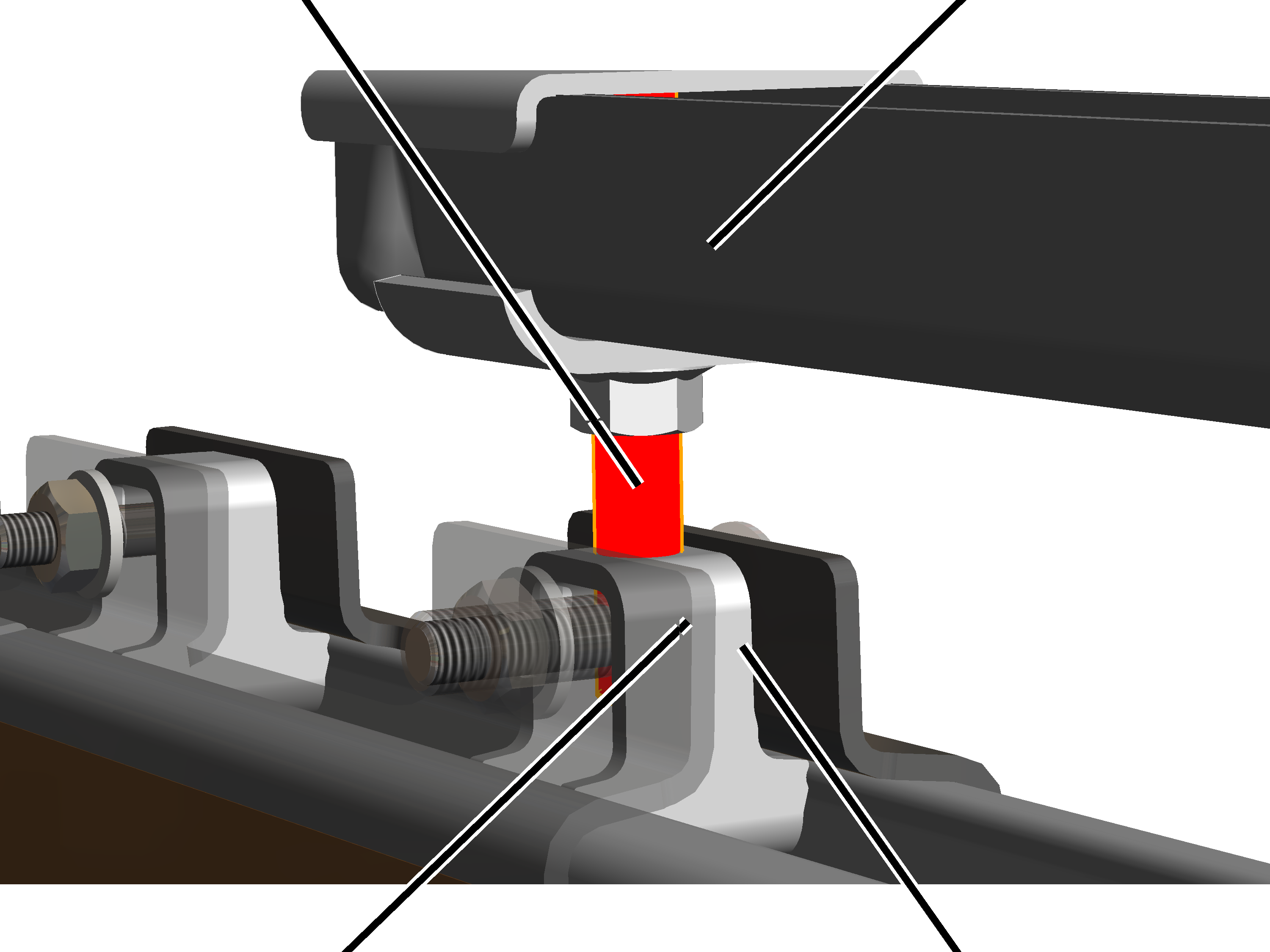
- Shorten the thread of the ceiling-mounted bracket
Preparing the ceiling-mounted bracket
On the ceiling-mounted bracket:
Ceiling-mounted bracket
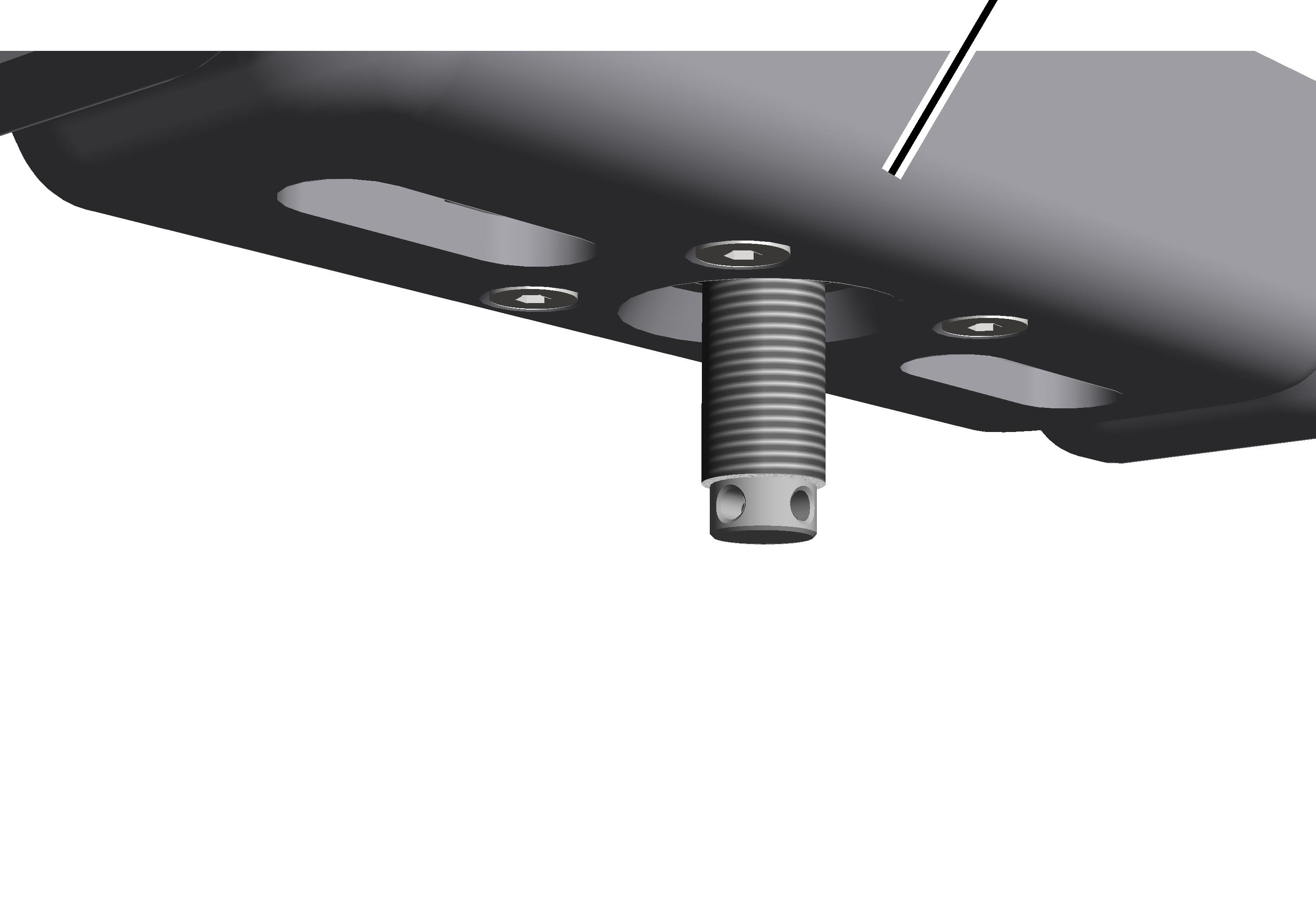
- There are no further preparations required for the ceiling-mounted bracket. The assembly of the tension nuts is described in the next sections.
The crane track will later be installed on the ceiling-mounted bracket.
Craneway suspension M16: installing an inclined suspension
The threaded rods from which the crane track will later be hung are now fitted on the installed ceiling-mounted bracket with articulated girder.
Overview:
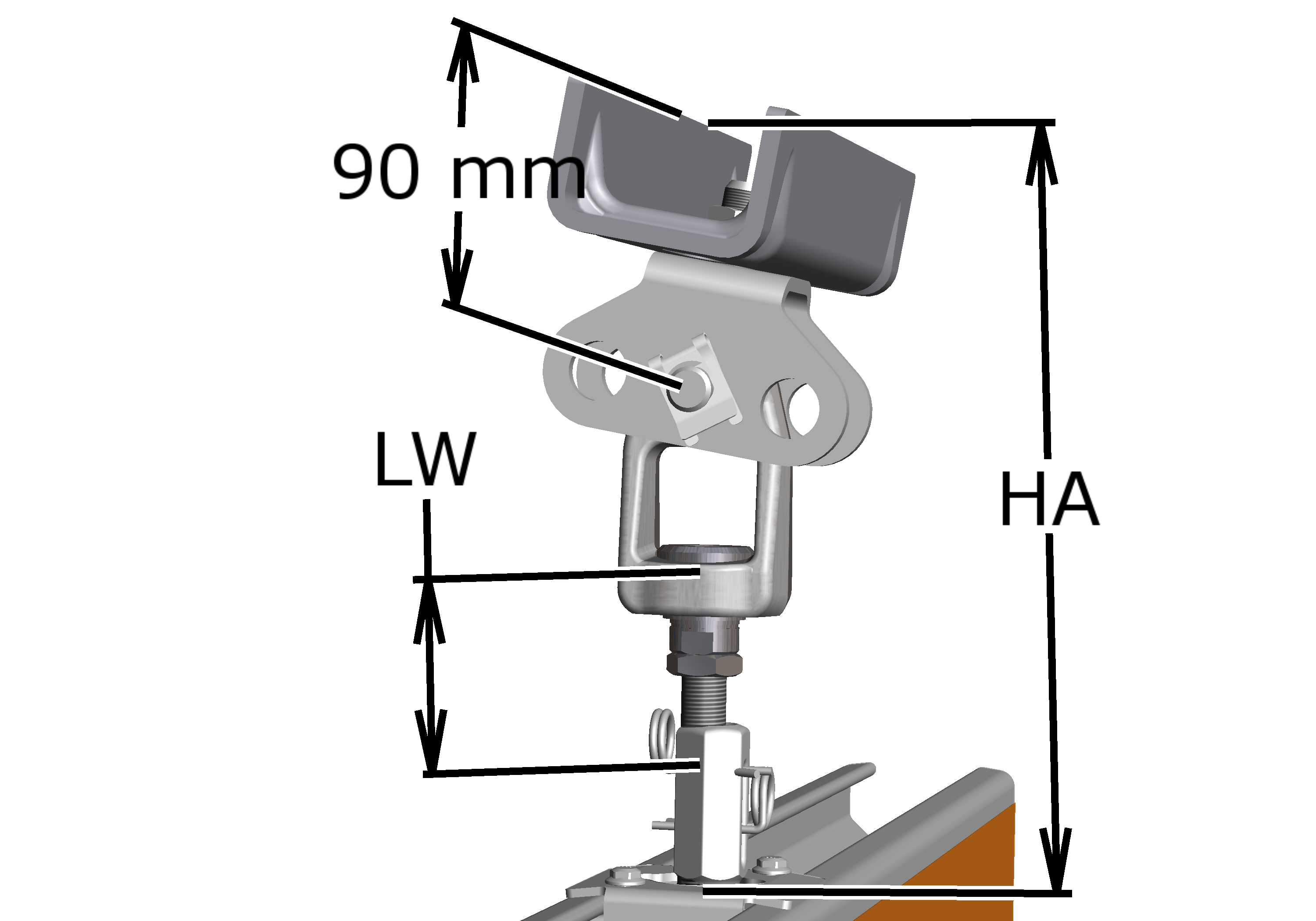
Size |
HA with LW 80 mm |
HA with LW from 100 mm |
|---|---|---|
HB110 |
HA = |
HA = |
HB150 |
HA = |
HA = |
HB190 |
HA = |
HA = |
HB240 |
HA = |
HA = |
Preparing the threaded rod
On upper end of the threaded rod:
Clamping jointTension nut
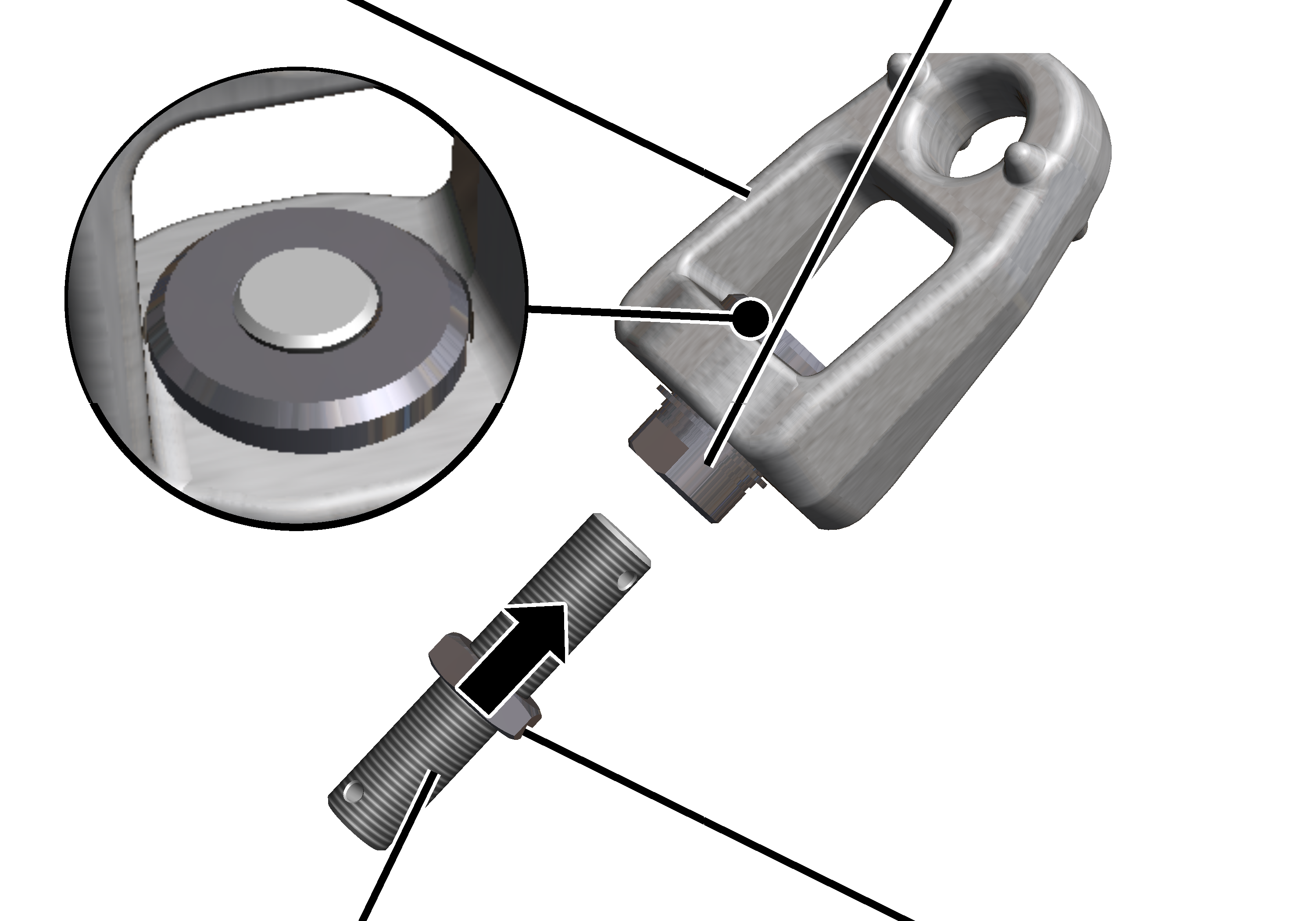
- Screw the M16x1.5 hexagonal nuts (2x) onto the shortened or lengthened threaded rod.
- Screw the threaded rod into the tension nut until the end of the threaded rod is flush with the tension nut on the inside (see enlarged section of the illustration)
- Lock with hexagonal nut.
The HB crane runway will later be installed on the lower end of the threaded rod.
Fastening the threaded rod
On the ceiling-mounted bracket:
SL safety clipArticulated girder
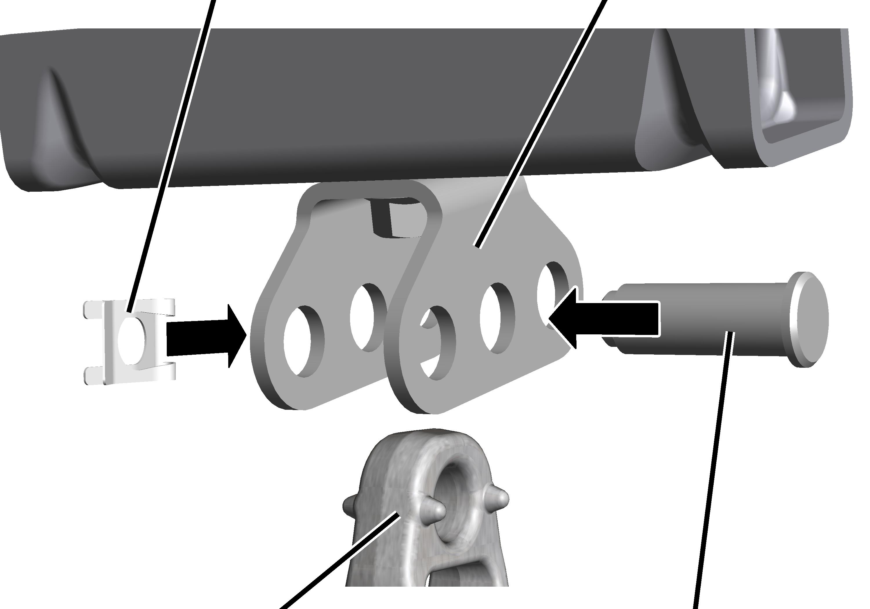
- Insert the clamping joint between the articulated girders on the ceiling-mounted bracket.
- Insert bolt through articulated girder and clamping joint.
- Secure bolt with SL safety clip.
Craneway suspension M16: installing a normal stiffener
The threaded rods from which the crane track will later be hung are now fitted on the installed ceiling-mounted bracket for the vertical load-bearing section and for the stiffener.
On the additional ceiling-mounted bracket for the stiffener, the individual parts of the stiffener are mounted and these are then connected with the vertical load-bearing section.
Overview:
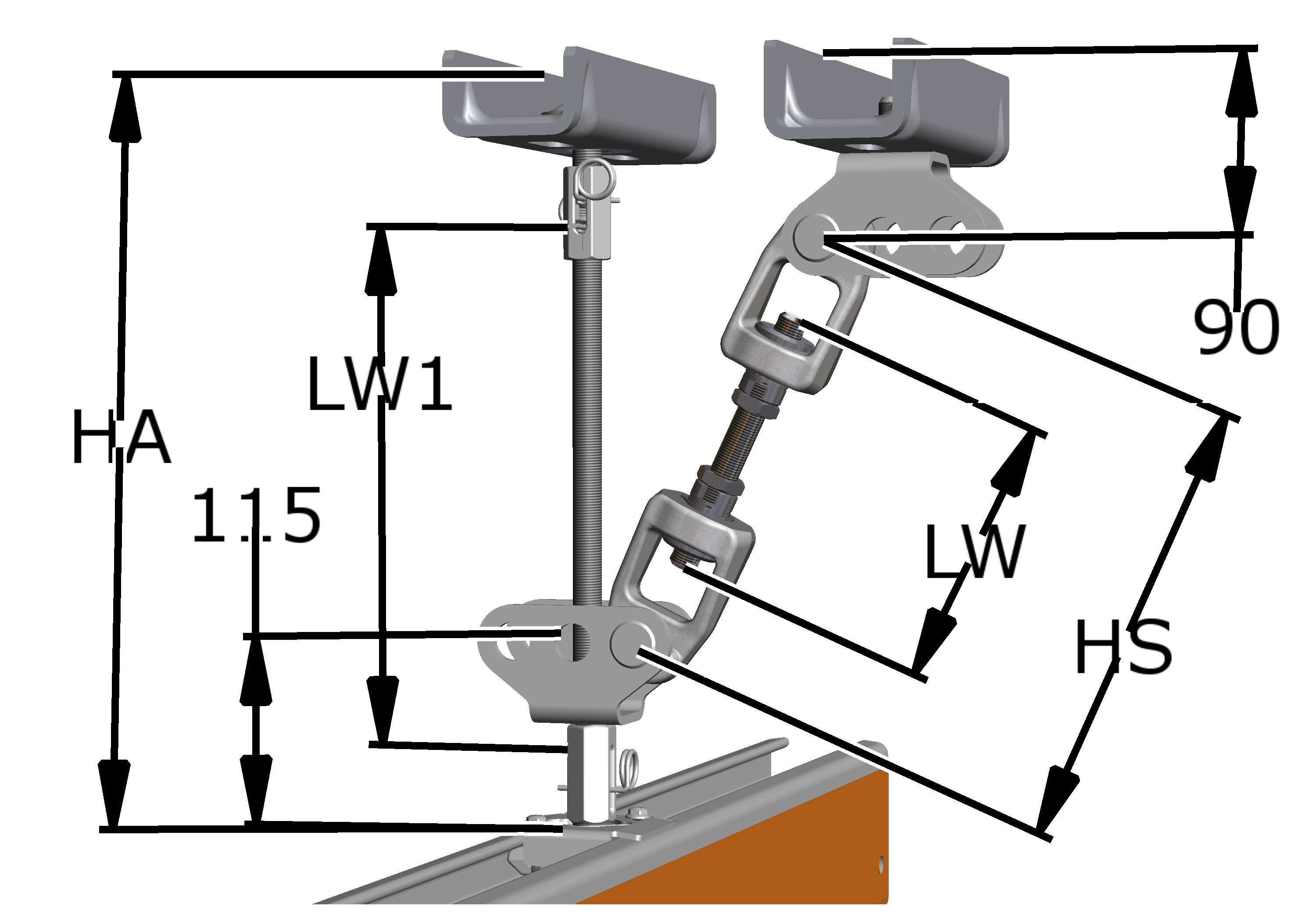
Size |
HA |
HS |
|---|---|---|
HB110 |
HA = |
HS = |
HB150 |
HA = |
HS = |
HB190 |
HA = |
HS = |
HB240 |
HA = |
HS = |
Minimum length of the threaded rod on the vertical load-bearing section (LW1) is 300 mm
Installing the vertical load-bearing section
On the ceiling-mounted bracket:
Cross-drilled holeSpring cotter
- Screw the coupling (both sides with right-hand thread) on the ceiling-mounted bracket.
- Screw the shortened or lengthened threaded rods in the coupling.
- Turn the coupling so that the boreholes are visible.
The threaded rod has a cross-drilled hole on the ceiling-mounted bracket. Turn the coupling in such a way that the hole facing across the later HB crane runway is used.
- Insert spring cotters (2x).
Fit articulated girder and tensioning nut on the vertical load-bearing section
On the lower end of the threaded rods an articulated girder is now installed. This is where the vertical load-bearing section will later be connected with the stiffener.
On lower end of the threaded rod:
Hexagonal nutsThreaded rod
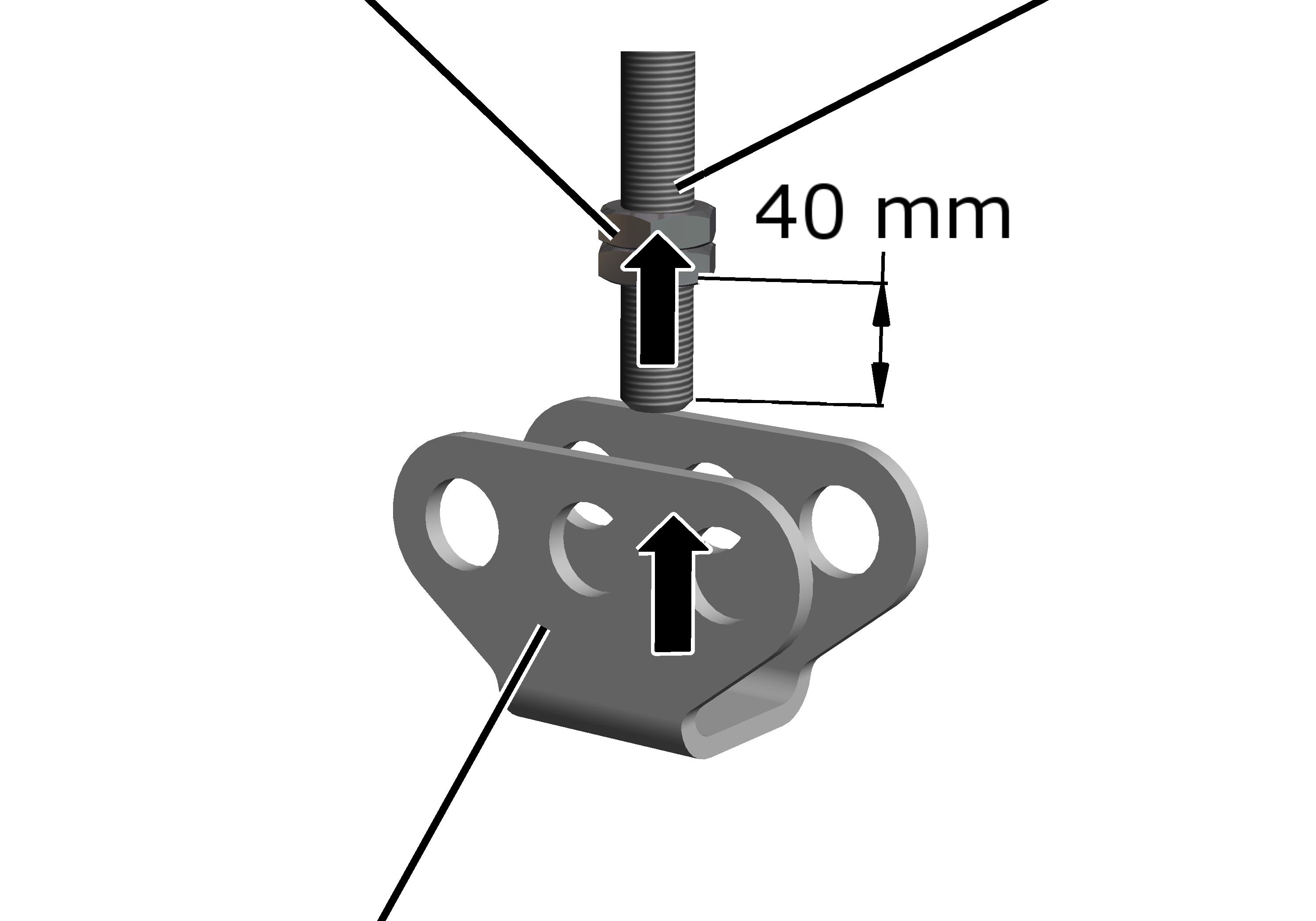
- Screw the M16x1.5 hexagonal nuts (2x) about 40 mm onto the threaded rod.
- Insert the articulated girder on the threaded rod.
Installing the stiffener
The ceiling-mounted bracket of the stiffener is now connected with the previously mounted articulated girder of the vertical load-bearing section.
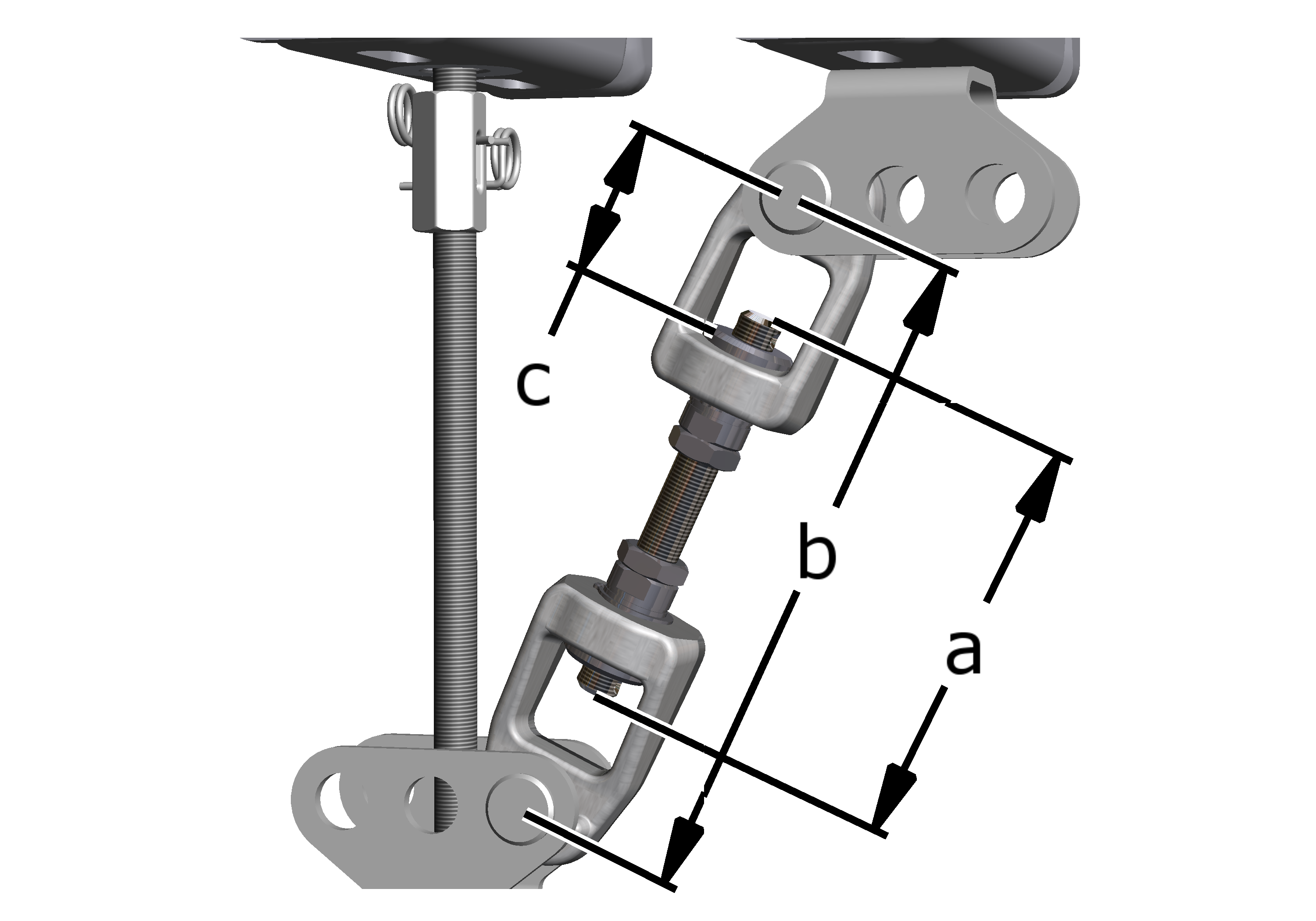
- Determine the length of the threaded rod (a) for the stiffener.
To do this, measure the distance of the two holes (b) between the articulated girders and subtract twice the inner length of the clamping joint (c = 2x 56 mm).
- Shorten the threaded rods for the stiffener to the determined length.
On both ends of the threaded rod:
Threaded rodTension nut
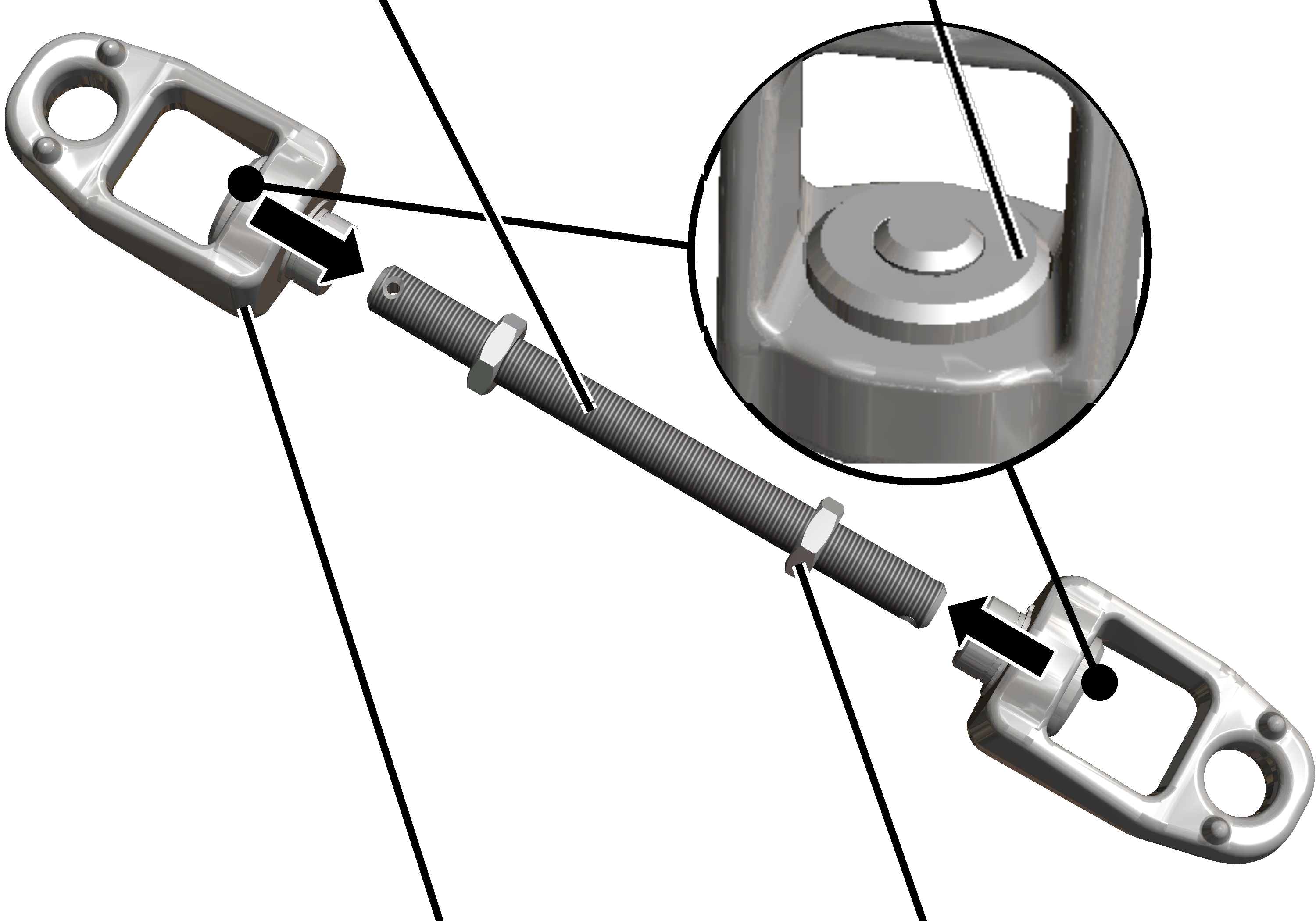
- Screw the M16x1.5 hexagonal nuts (2x) onto the shortened or lengthened threaded rod.
- Screw the threaded rod into the tension nuts (2x) until the end of the threaded rod is flush with the tension nut on the inside (see enlarged section of the illustration).
- Lock with hexagonal nut.
Fastening the stiffener
On the ceiling-mounted bracket:
Ceiling-mounted bracket of the vertical load-bearing sectionCeiling-mounted bracket of the stiffener
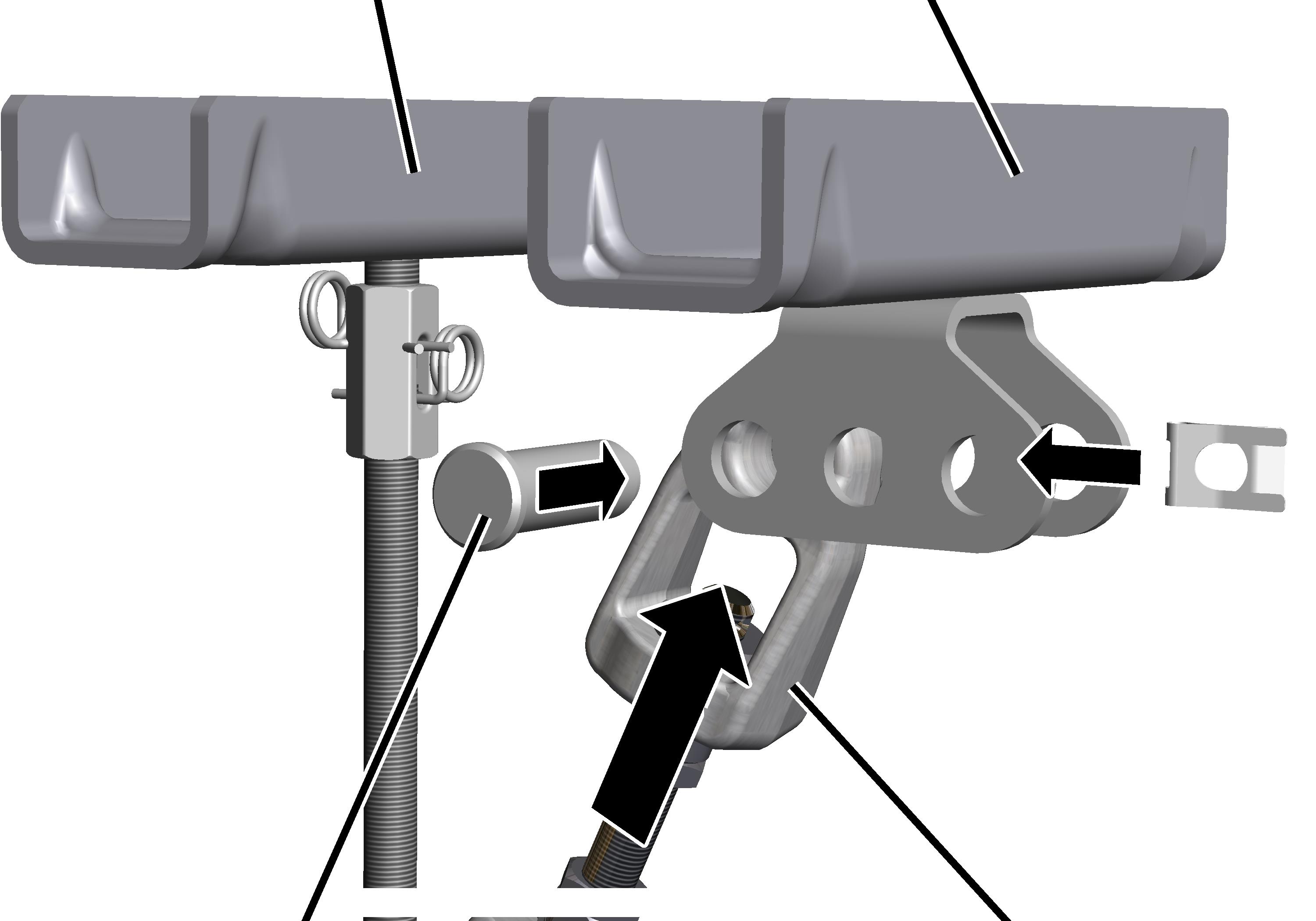
- Insert the clamping joint between the articulated girders on the ceiling-mounted bracket of the stiffener. Use the hole facing the vertical load-bearing section.
- Insert bolt through articulated girder and clamping joint.
- Secure bolt with SL safety clip.
On the threaded rod:
BoltClamping joint
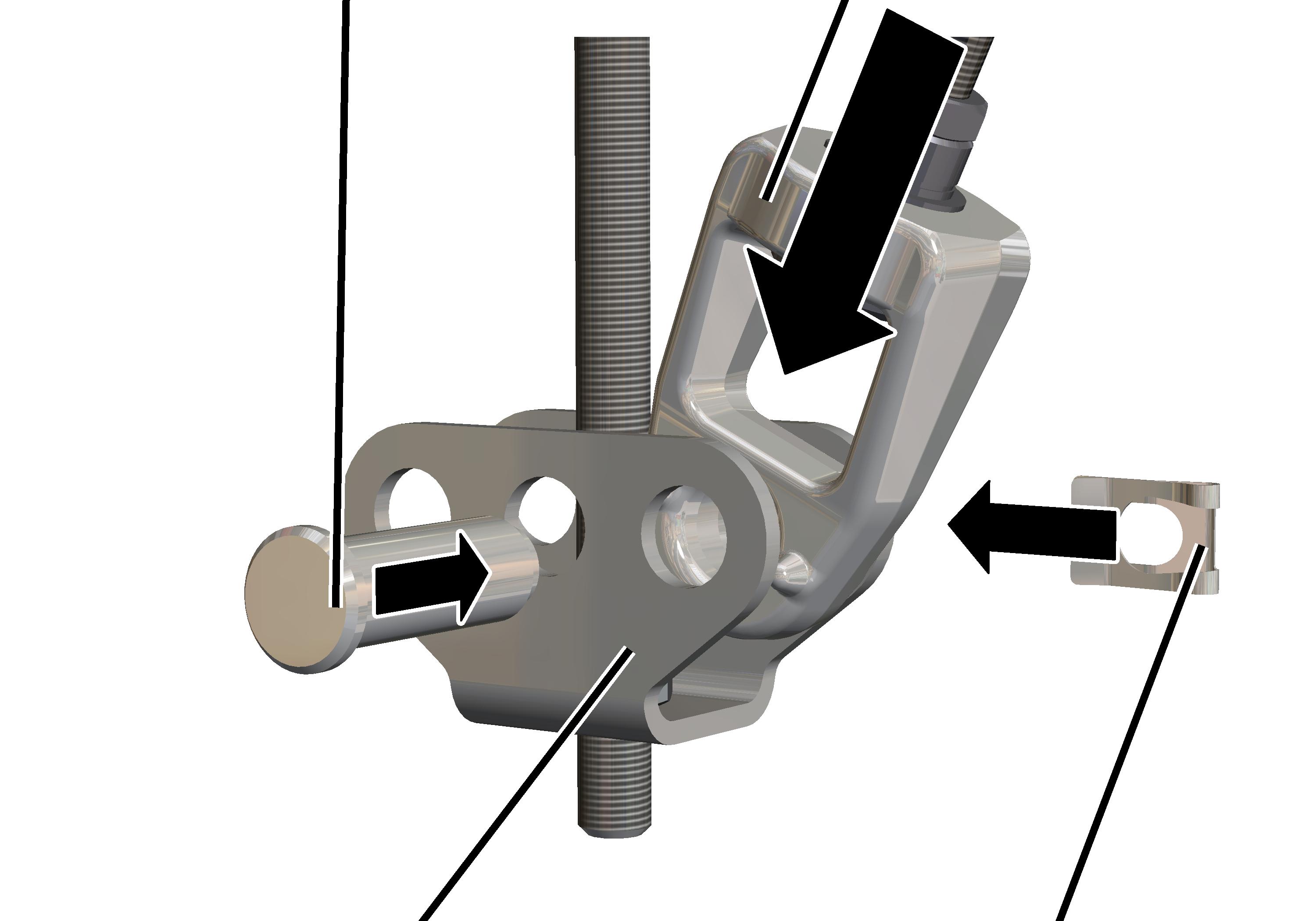
- Insert clamping joint between the articulated girder on the vertical load-bearing section. Use the hole facing the stiffener.
- Insert bolt through articulated girder and clamping joint.
- Secure bolt with SL safety clip.
The HB crane runway will later be installed on the lower end of the threaded rod.
Checking for play of the stiffener
- Check for play of the stiffener.
The stiffener should not hang loosely or wobble between the two articulated girders. It must sit firmly and without play on the articulated girders.
If the stiffener has play:
- Turn the tension nut in the clamping joint to tension the threaded rod until the stiffener lies free of play between the articulated girders.
Craneway suspension M16: installing an inclined stiffener
The threaded rods from which the crane track will later be hung are now fitted on the installed ceiling-mounted bracket for the vertical load-bearing section.
On the additional ceiling-mounted bracket for the stiffener, the individual parts of the stiffener are mounted and these are then connected with the vertical load-bearing section.
Overview:
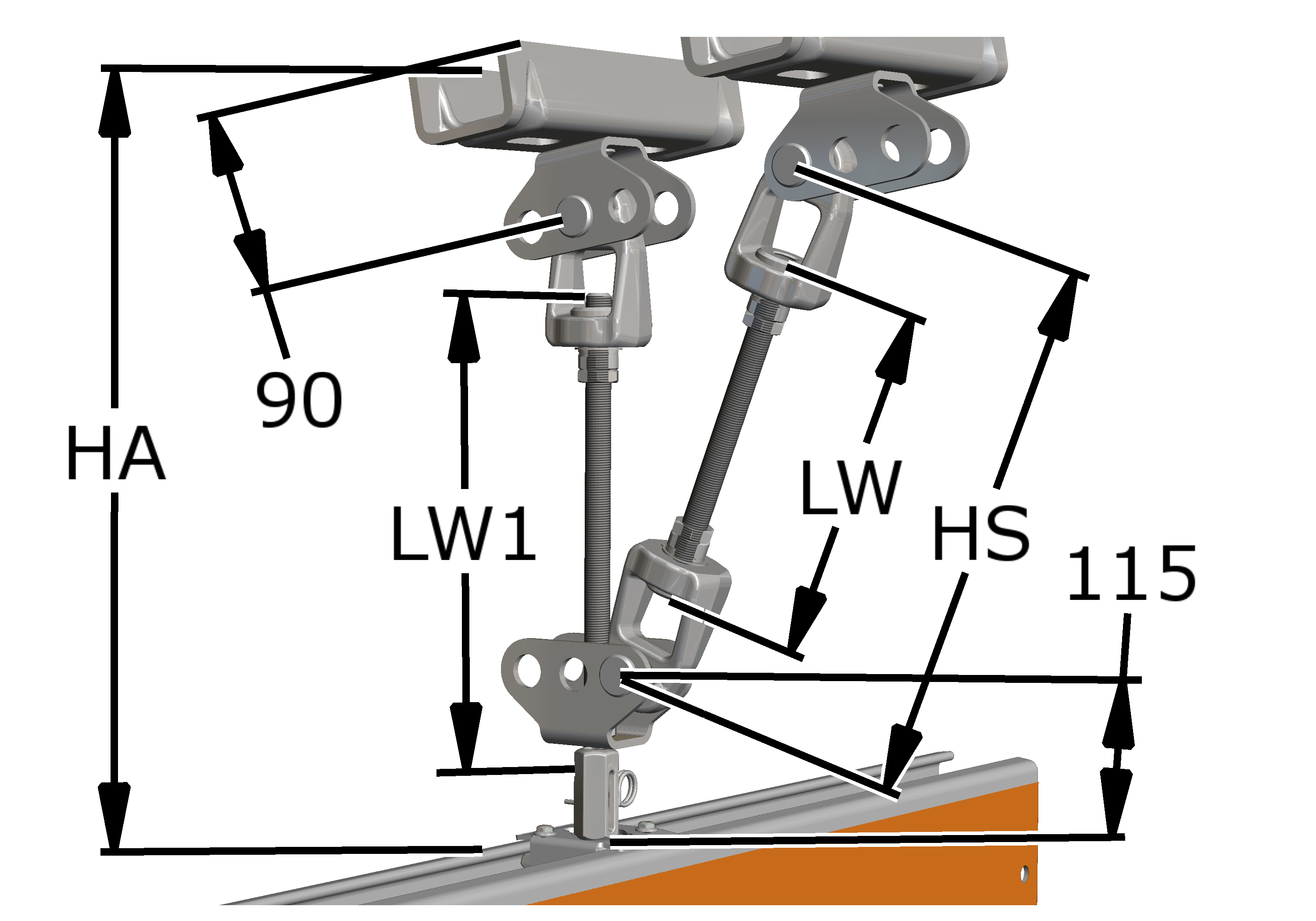
Size |
HA |
HS |
|---|---|---|
HB110 |
HA = |
HS = |
HB150 |
HA = |
HS = |
HB190 |
HA = |
HS = |
HB240 |
HA = |
HS = |
Minimum length of the threaded rod on the vertical load-bearing section (LW1) is 300 mm
Installing the vertical load-bearing section
On upper end of the threaded rod:
Clamping jointTension nut
- Screw the M16x1.5 hexagonal nuts (2x) onto the shortened or lengthened threaded rod.
- Screw the threaded rod into the tension nut until the end of the threaded rod is flush with the tension nut on the inside (see enlarged section of the illustration)
- Lock with hexagonal nut.
On the ceiling-mounted bracket:
SL safety clipArticulated girder
- Insert the clamping joint between the articulated girders on the ceiling-mounted bracket.
- Insert bolt through articulated girder and clamping joint.
- Secure bolt with SL safety clip.
Fit articulated girder and tensioning nut on the vertical load-bearing section
On the lower end of the threaded rods an articulated girder is now installed. This is where the vertical load-bearing section will later be connected with the stiffener.
On lower end of the threaded rod:
Hexagonal nutsThreaded rod
- Screw the M16x1.5 hexagonal nuts (2x) about 40 mm onto the threaded rod.
- Insert the articulated girder on the threaded rod.
Installing the stiffener
The ceiling-mounted bracket of the stiffener is now connected with the previously mounted articulated girder of the vertical load-bearing section.
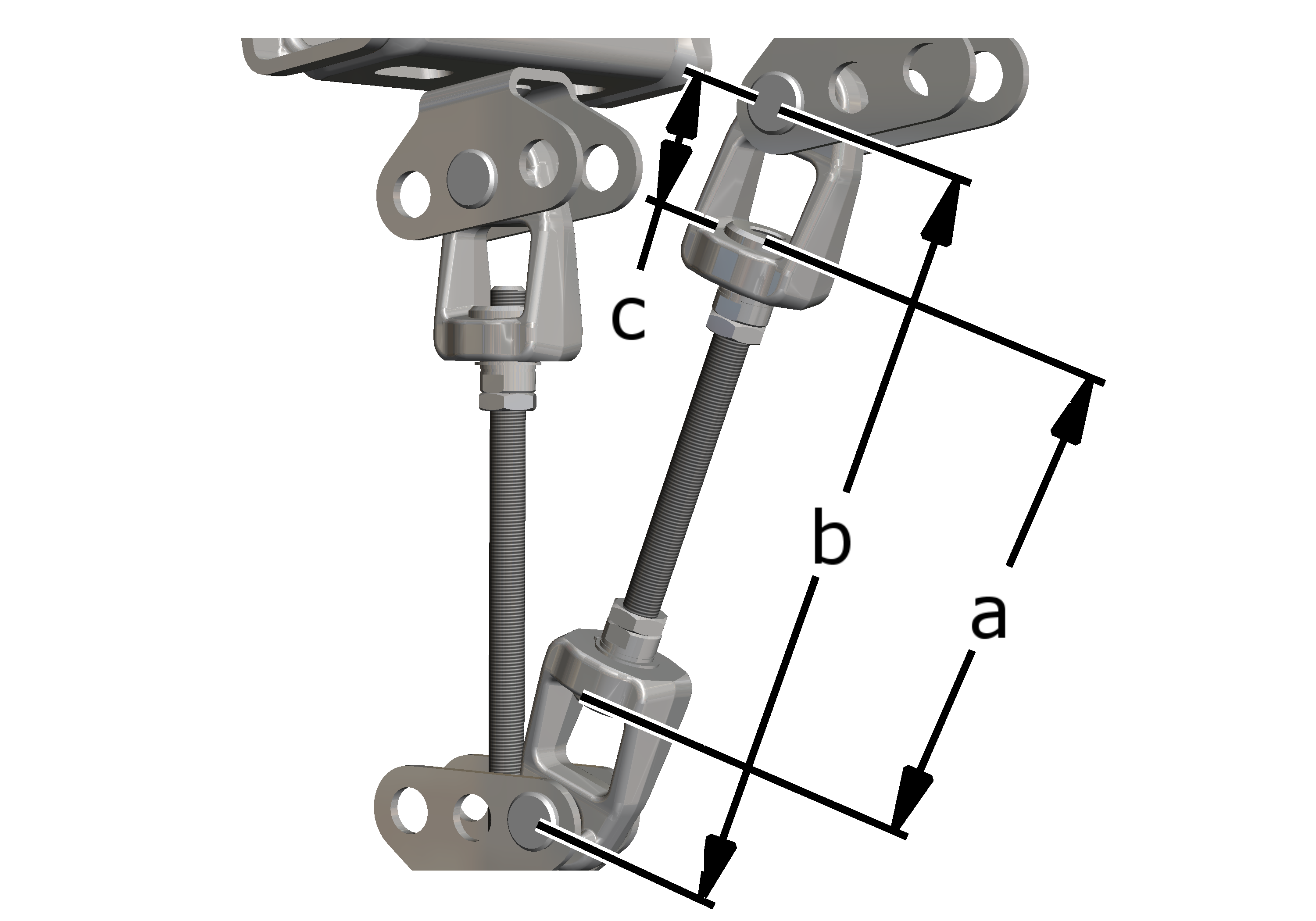
- Determine the length of the threaded rod (a) for the stiffener.
To do this, measure the distance of the two holes (b) between the articulated girders and subtract twice the inner length of the clamping joint (c = 2x 56 mm).
- Shorten the threaded rods for the stiffener to the determined length.
On both ends of the threaded rod:
Threaded rodTension nut
- Screw the M16x1.5 hexagonal nuts (2x) onto the shortened or lengthened threaded rod.
- Screw the threaded rod into the tension nuts (2x) until the end of the threaded rod is flush with the tension nut on the inside (see enlarged section of the illustration).
- Lock with hexagonal nut.
Fastening the stiffener
On the ceiling-mounted bracket:
Ceiling-mounted bracket of the stiffenerArticulated girder
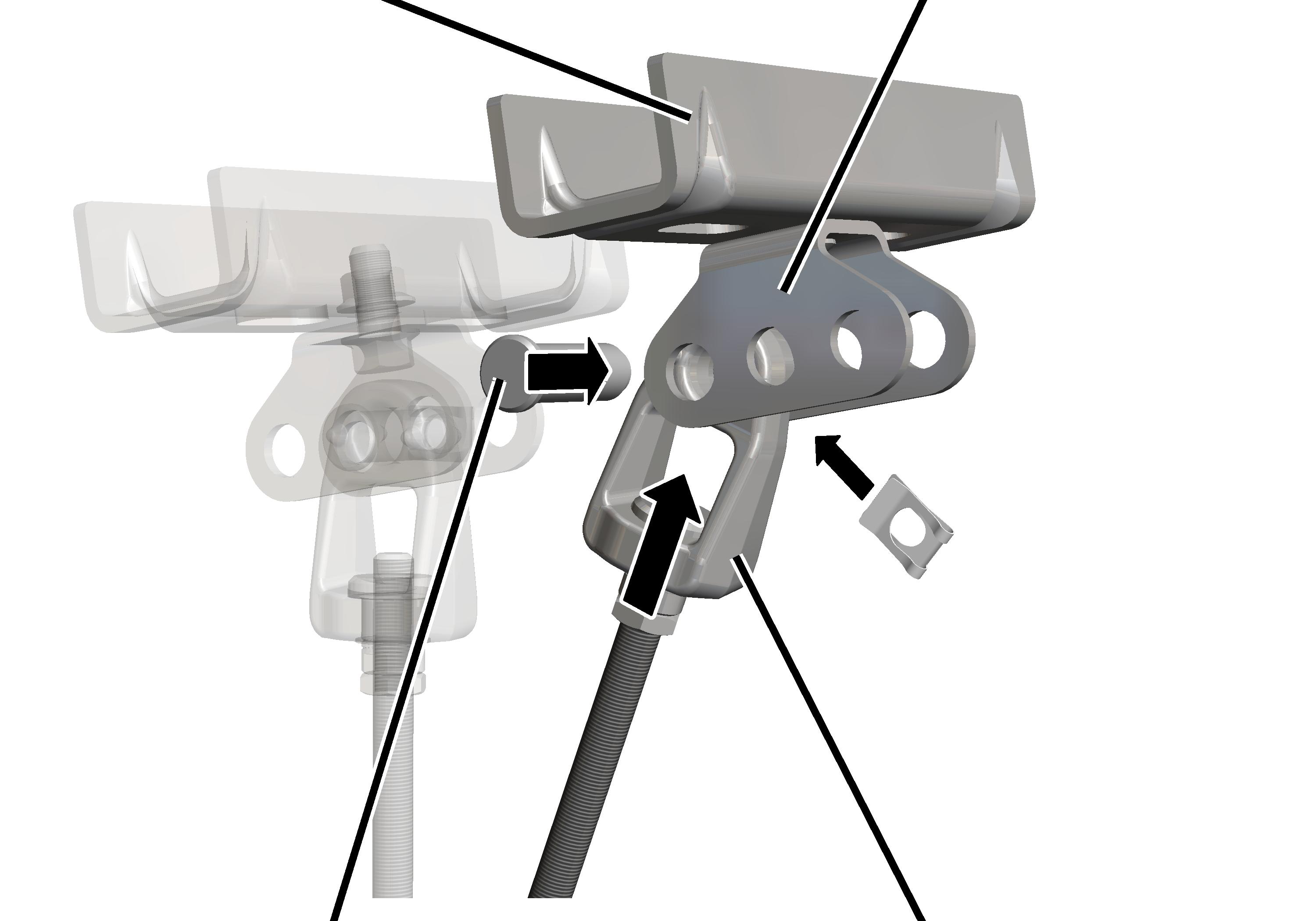
- Insert the clamping joint between the articulated girders on the ceiling-mounted bracket of the stiffener. Use the hole facing the vertical load-bearing section.
- Insert bolt through articulated girder and clamping joint.
- Secure bolt with SL safety clip.
On lower end of the stiffener:
BoltClamping joint
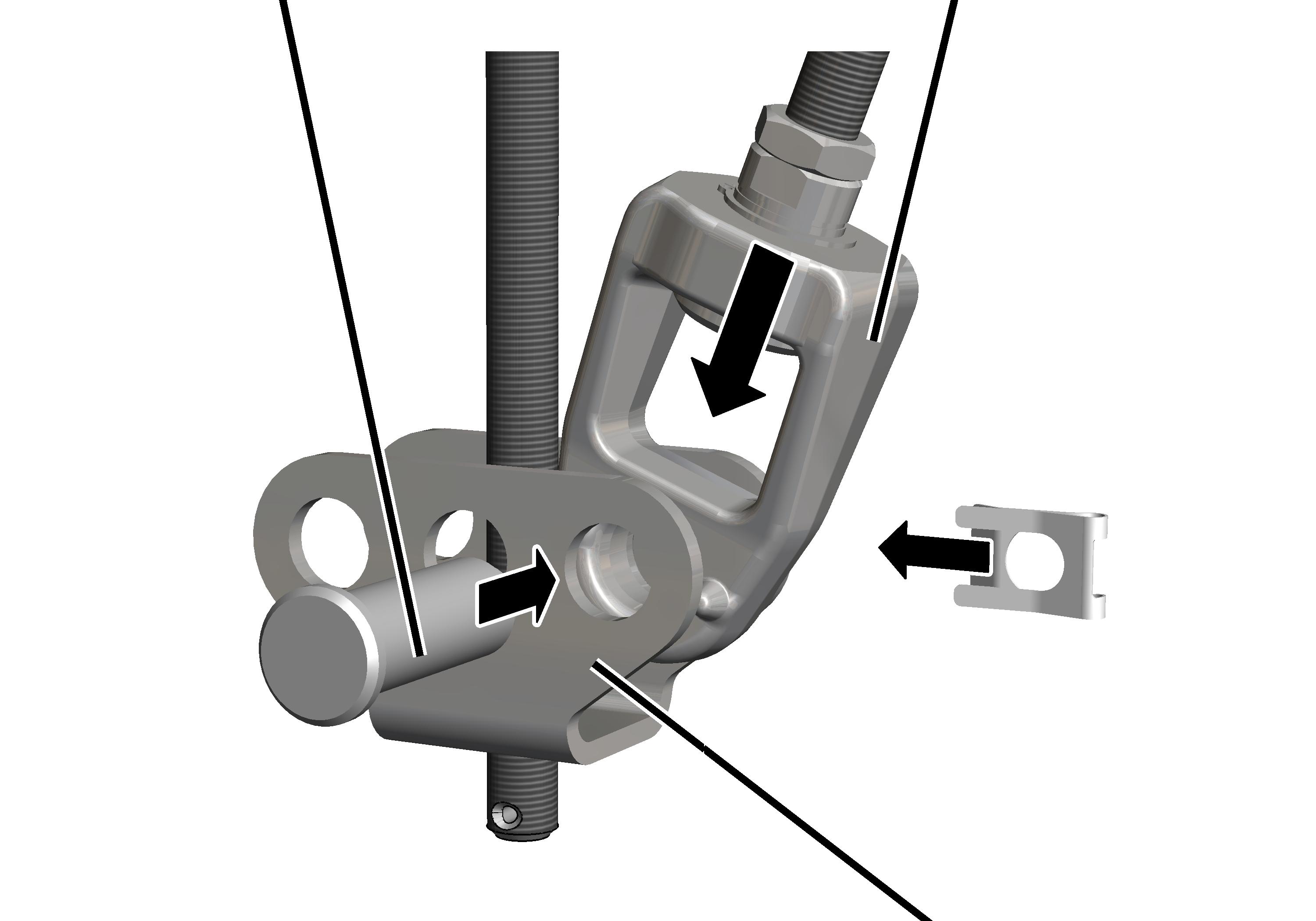
- Insert clamping joint between the articulated girder on the vertical load-bearing section. Use the hole facing the stiffener.
- Insert bolt through articulated girder and clamping joint.
- Secure bolt with SL safety clip.
The HB crane runway will later be installed on the lower end of the threaded rod.
Checking for play of the inclined stiffener
- Check for play of the stiffener.
The stiffener should not hang loosely or wobble between the two articulated girders. It must sit firmly and without play on the articulated girders.
If the stiffener has play:
- Turn the tension nut in the clamping joint to tension the threaded rod until the stiffener lies free of play between the articulated girders.
Craneway suspension M16: installing the V-suspension
The threaded rods from which the crane track will later be hung are now fitted on the installed ceiling-mounted bracket for the V-suspension.
Overview:
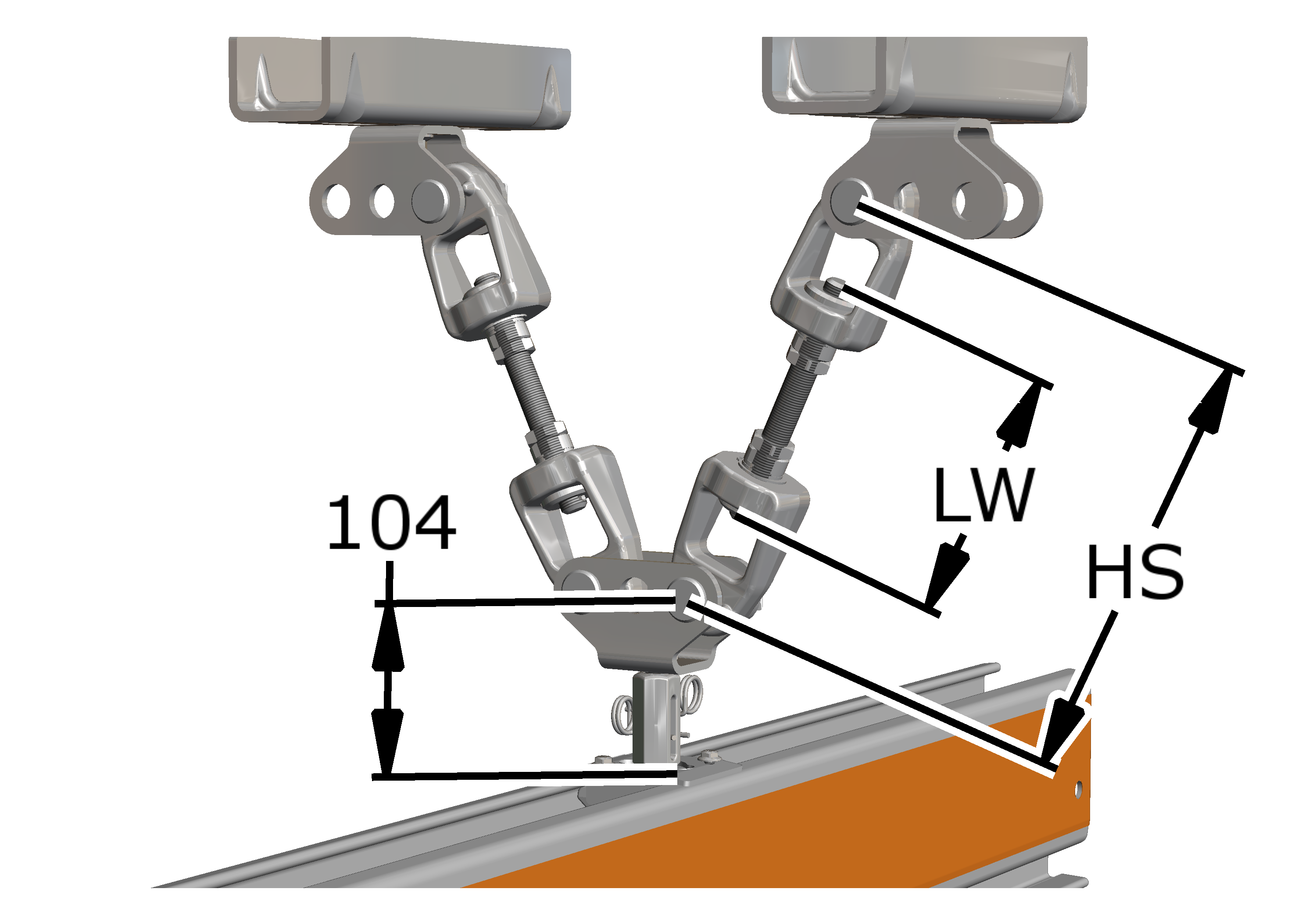
Size |
HS |
|---|---|
HB110 |
HS = 80 + LW ± 30 mm |
HB150 |
HS = 80 + LW ± 30 mm |
HB190 |
HS = 80 + LW ± 30 mm |
HB240 |
HS = 80 + LW ± 30 mm |
Installing a V-suspension
On both ends of the two threaded rods:
Threaded rod
- Screw the M16x1.5 hexagonal nuts (2x) onto the shortened or lengthened threaded rod.
- Screw the threaded rod into the tension nuts (2x) until the end of the threaded rod is flush with the tension nut on the inside (see enlarged section of the illustration).
- Lock with hexagonal nut.
On both ceiling-mounted brackets:
BoltCeiling-mounted bracket
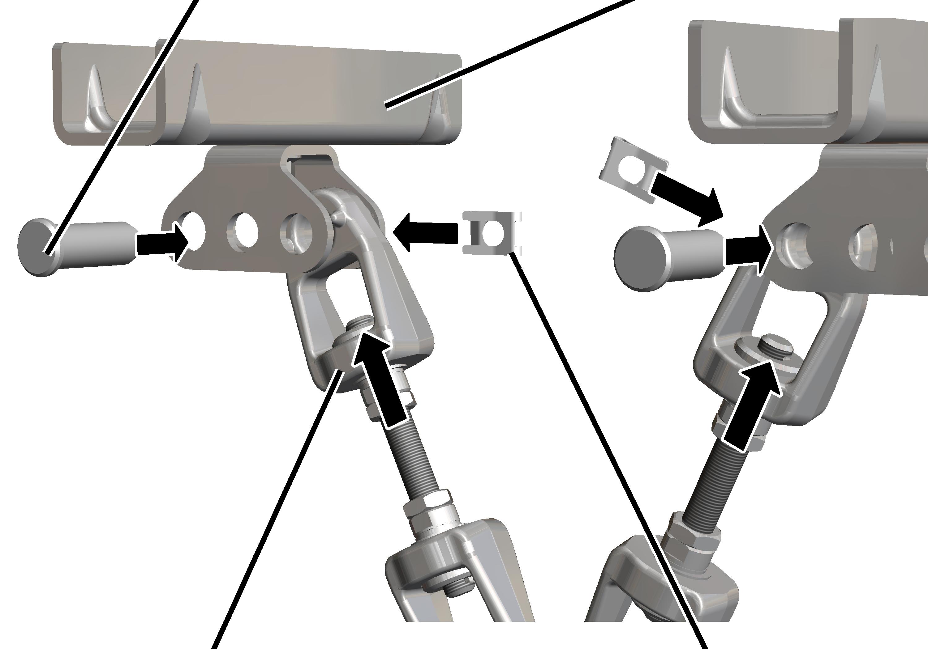
- Insert the clamping joint between the articulated girders on the ceiling-mounted bracket of the V-suspension. Always use the inner hole.
- Insert bolt through articulated girder and clamping joint.
- Secure bolt with SL safety clip.
Installing the articulated girder
A later height adjustment is not possible on the articulated girder of the V-suspension.
The height can only be altered through the length of the two inclined threaded rods.
Threaded rodArticulated girder
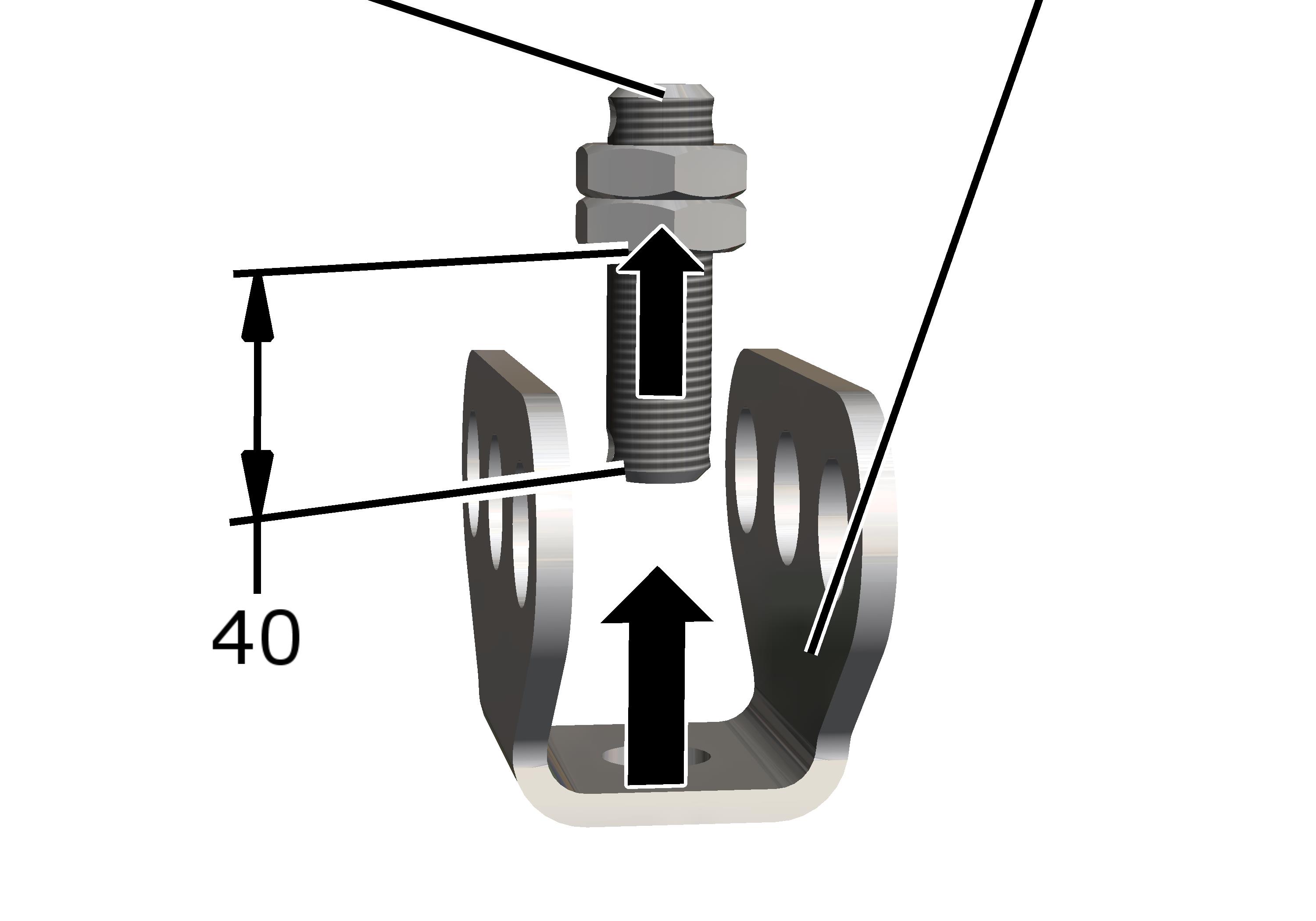
- Screw the M16x1.5 hexagonal nuts (2x) about 40 mm onto the threaded rod (80 mm long).
- Insert the articulated girder on the threaded rod.
Fixing the V-suspension
On the lower end of the threaded rods:
Clamping joints
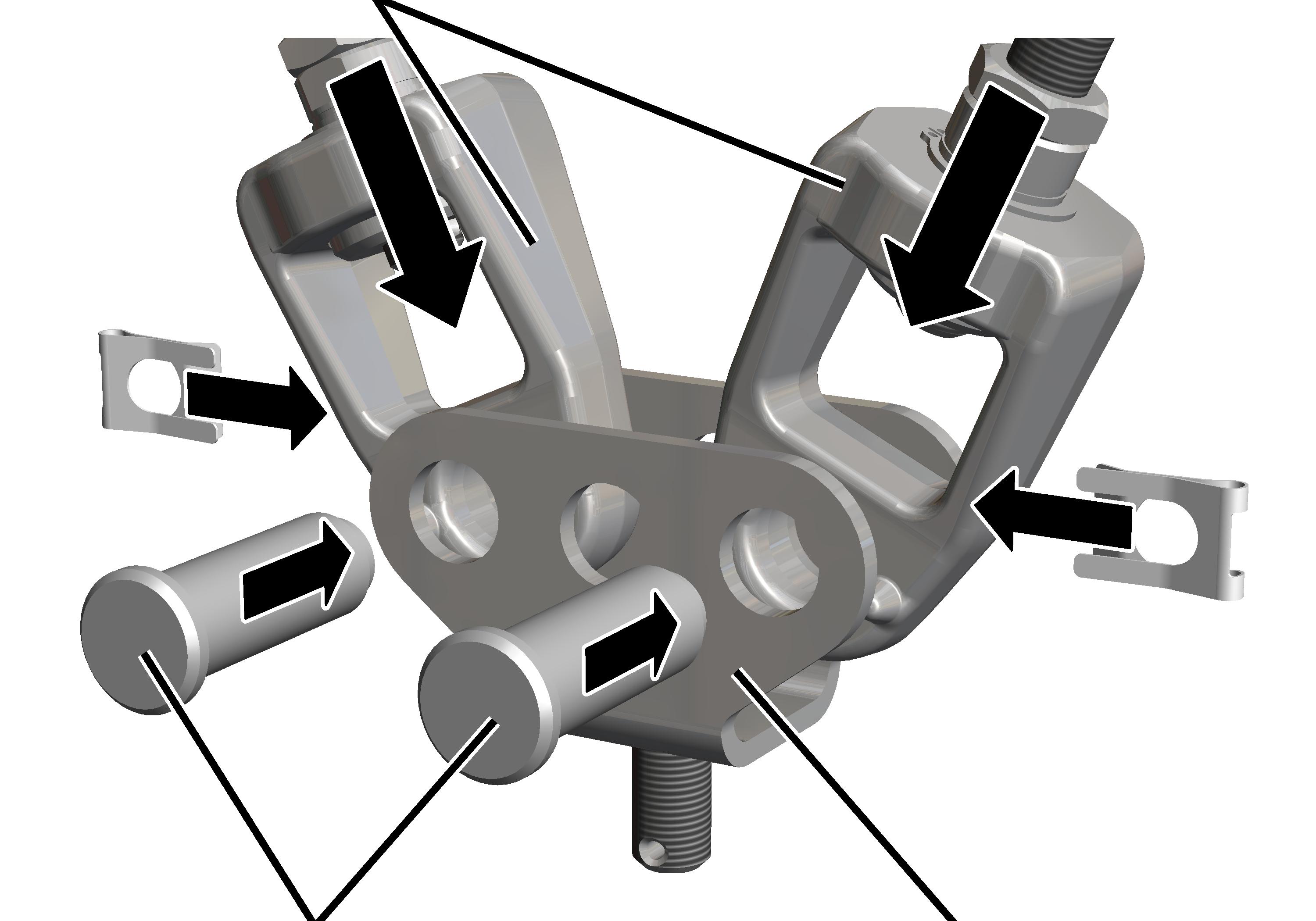
- Insert the clamping joints between the articulated girders of the V-suspension. Use the two outer holes.
- Insert bolt through articulated girder and clamping joint.
- Secure bolt with SL safety clip.
The HB crane runway will later be installed on the lower end of the threaded rod.
Connecting steel profile rail sections
Depending on the length of the individual profile rail sections, the number of suspensions, the on-site building conditions and the length of the crane track, several profile rail sections should be connected with each other on the floor if possible.
The connected profile rail sections must be able to be raised and brought underneath the suspensions safely and without posing additional hazards.
If this is not possible, the profile rail sections must first be fixed individually or as sections on the suspension and then afterward fully joined with each other. When doing this, it must be ensured that there is adequate space underneath the suspensions, especially in the case of short suspensions.
Laying out the profile rail sections
- The profile rail sections must be laid out on the building floor the way they are to be later installed.
The specified dimensions, positions and clearances must be followed exactly.
Removing the protective film
The profile rail sections are laminated at the sides. The protective film is removed before further assembly.
Protective film
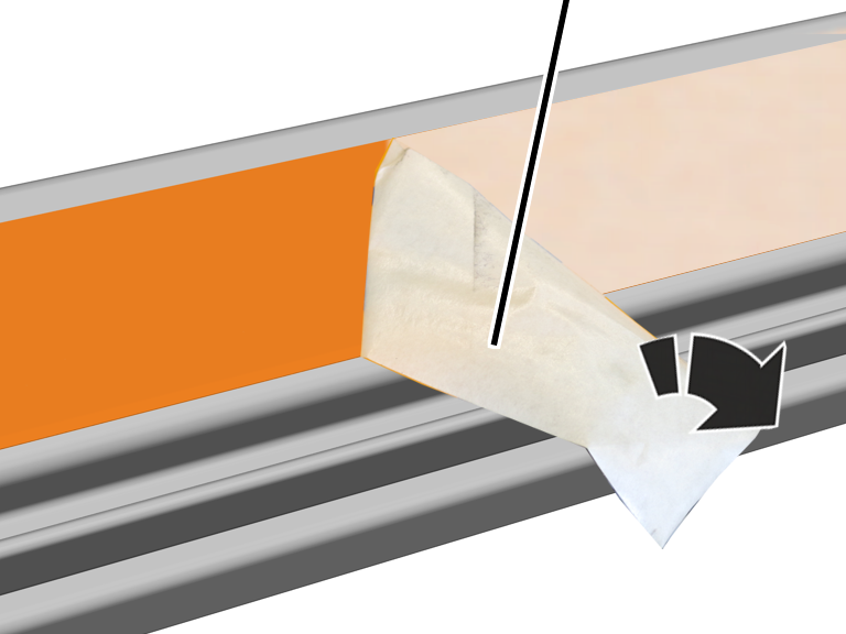
- Pull off the protective film at a sharp angle from the side lamination.
Combining profile rail sections
At each profile joint:
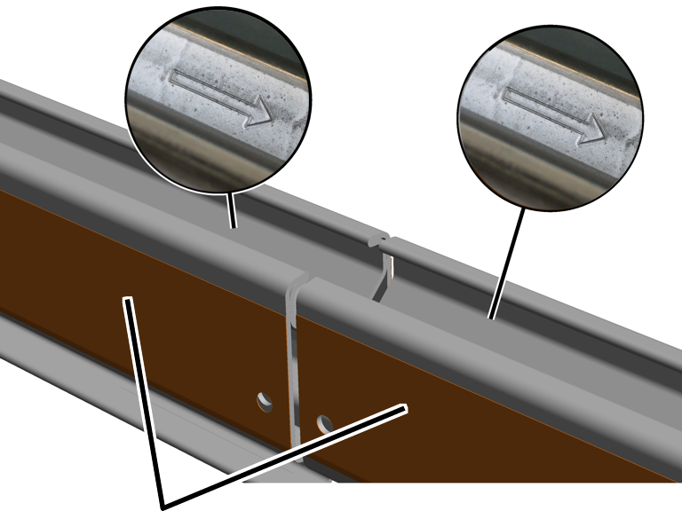
- Turn the profile rail sections so that the arrows on all of them point in the same direction.
- Lay the profile rail sections flush to one another.
The profile rail sections can be directly flush to one another. The must not be more than 2 mm apart.
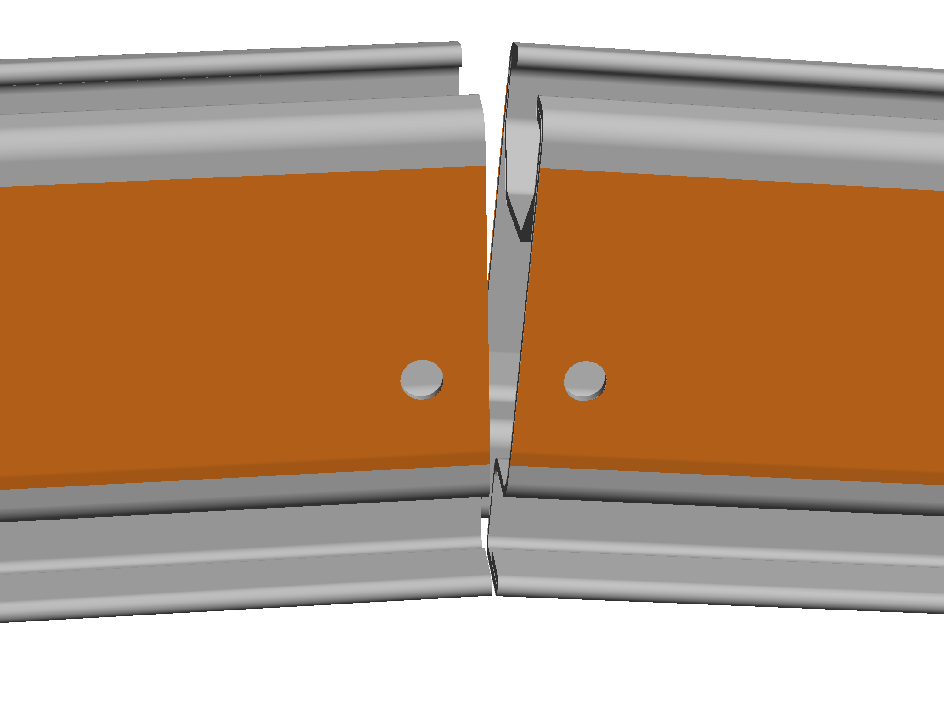
- Raise the profile rail sections just in front of the profile joint by about 5 cm (e.g. on the floor with a wooden beam or, with suspended assembly, by slightly lowering the unassembled profile rail section).
- In this way, the profile rail sections join at a slight angle to one another. This ensures that despite the camber (the profile rail sections are arched upward slightly) the distance at the bottom between the profile rails is as small as possible.
Inserting the spacer parts
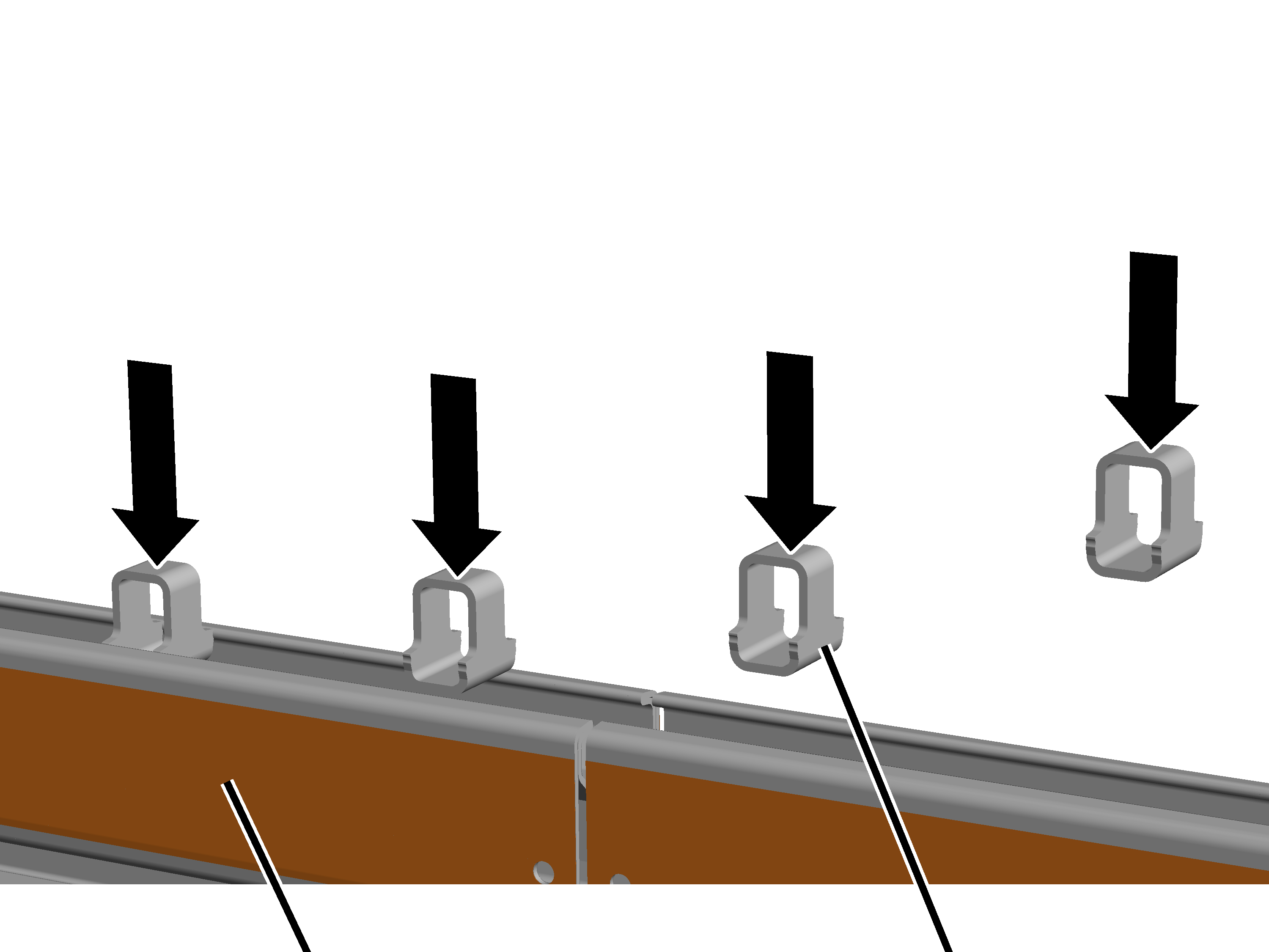
- Insert spacer parts from above in the left and right profile rail sections and, if necessary, knock them slightly into place.
- The spacer parts are clamped in the profile head but can still slide back and forth.
Inserting the clamping plate
Only with HB240
There are two different clamping plates available (with brackets or joining rib).
- If the distance from a suspension to the profile joint is maximally 600 mm, use the clamping plate with brackets (length 700 mm):
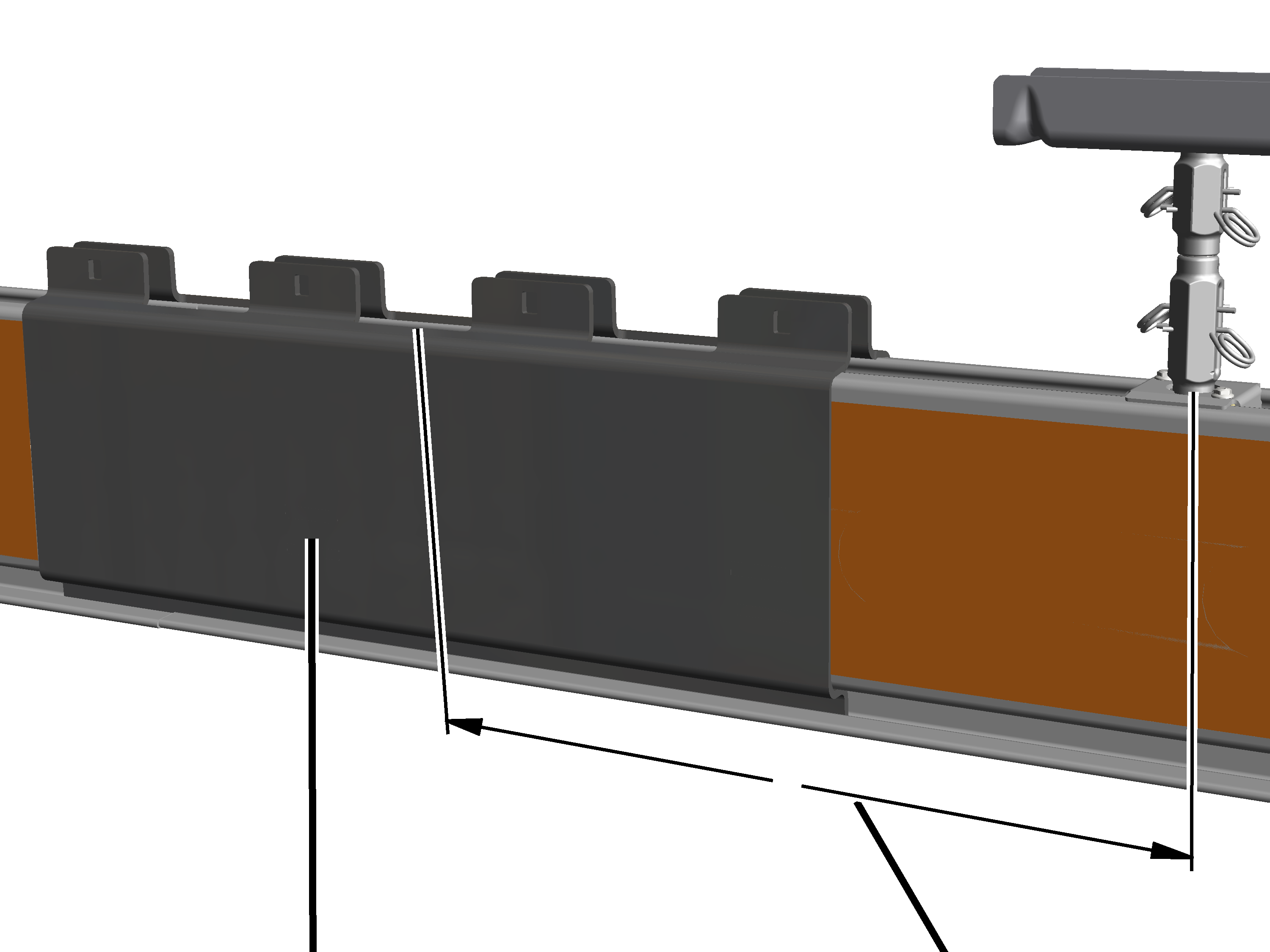
- If the distance from a suspension to the profile joint is greater than 600 mm, use the clamping plate with joining rib (length 1100 mm):
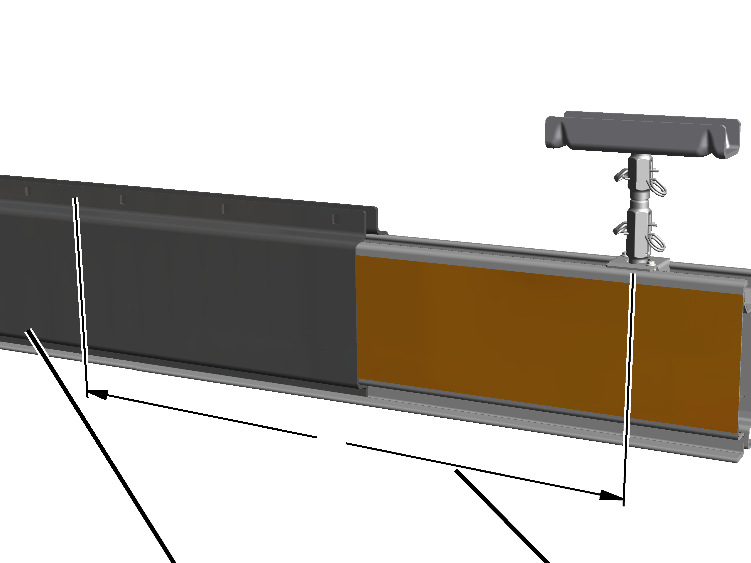
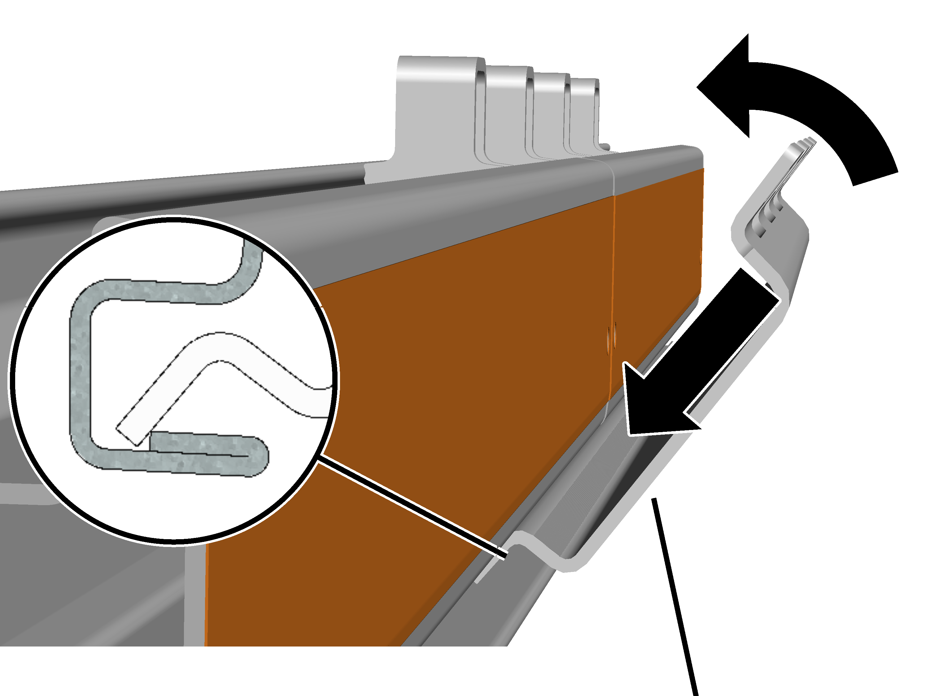
- Tilt the clamping plate slightly and insert it below in the profile rail section.
When doing this, insert the bottom of the clamping plate behind the edge on the profile rail section.
- Position the clamping plate so that it is exactly centred between the two profile rail sections.
- Press the top of the clamping plate against the profile rail section.
Bolting on the assembly aid
An assembly aid can now be bolted on at the top. It will make it easier to screw the clamping plates together.
On the clamping plate:
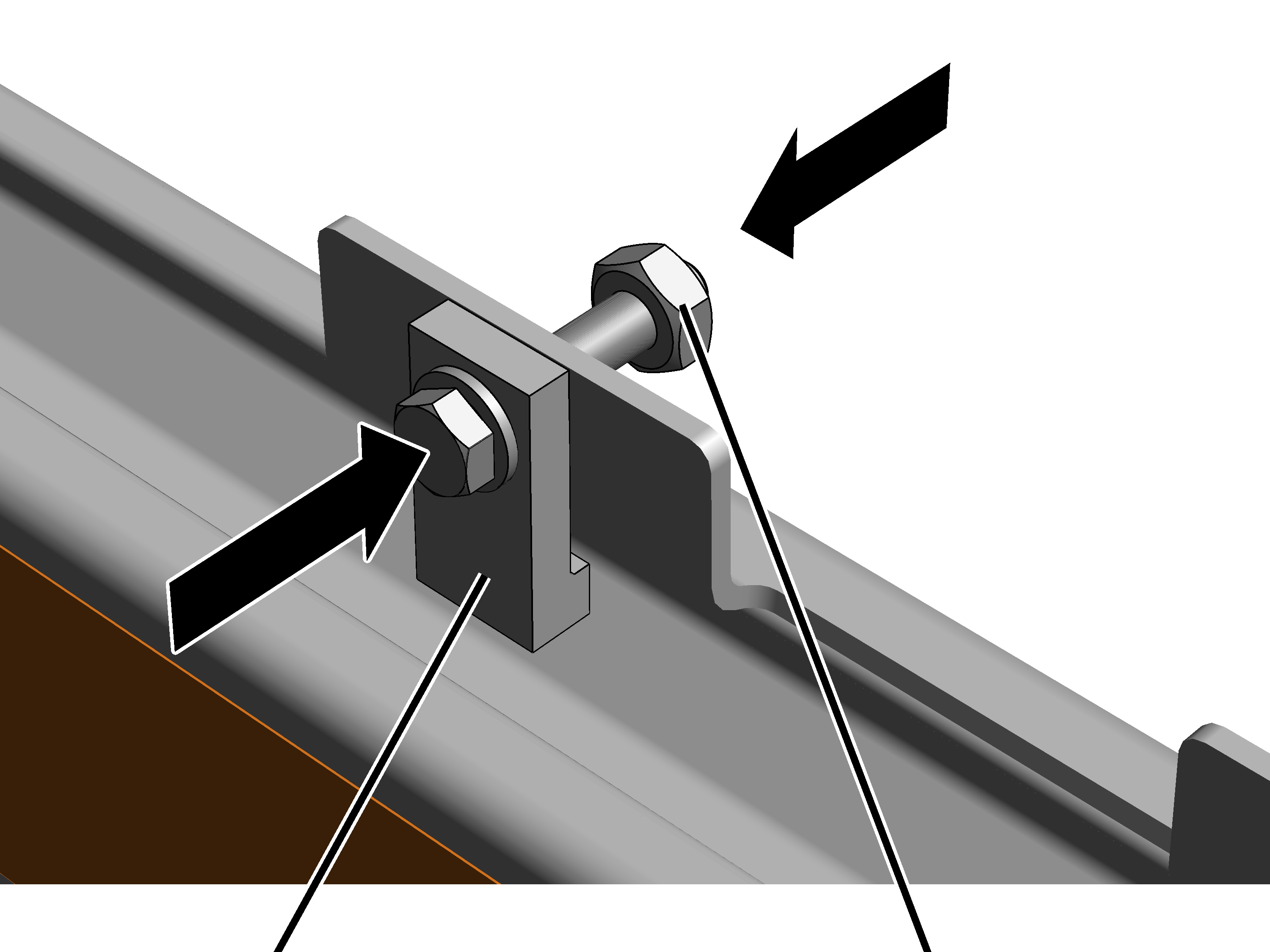
- Bolt the assembly aid on the outer lug with an M12 rib nut.
- The clamping plate is held by the assembly aid and can no longer fall down.
Bolting on a second clamping plate
- Insert the second clamping plate as described above on the opposite side and secure it with the assembly aid.
Only with a craneway suspension in the area of a clamping plate
This work step only applies if a suspension will be installed in the area of a profile joint.
Inserting the profile link
After both clamping plates have been inserted and secured with the assembly aids:
Bearing shell
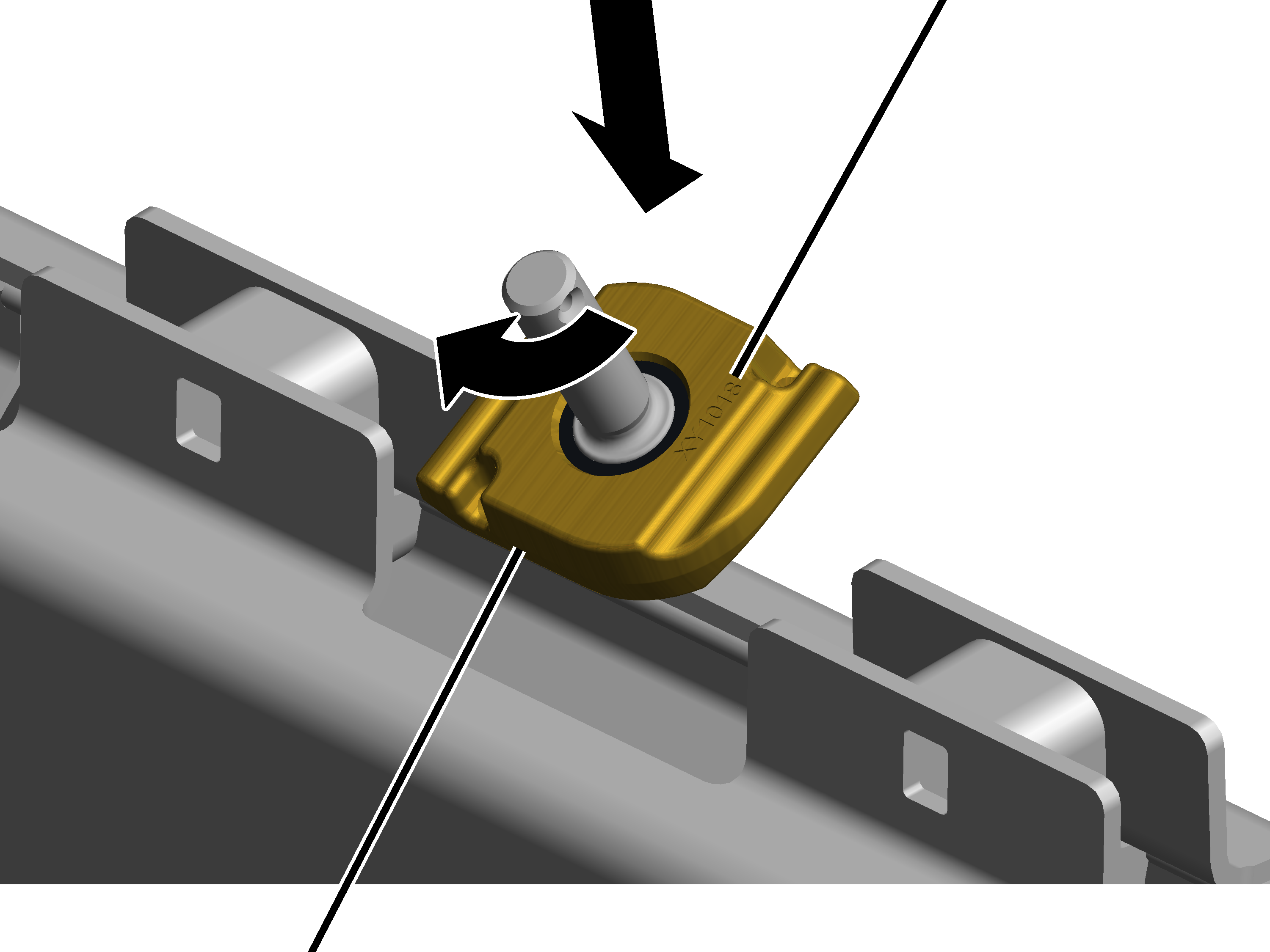
- Tilt the profile link and insert it from above at the required point in the profile head.
Once the clamping plate is installed, the profile link can no longer be shifted to a different lug.
The bearing shell in the ceiling-mounted bracket and on the profile link must always have the same colouring (silver or yellowish). Ceiling-mounted brackets and profile links with differently coloured bearing shells should not be installed together.
- Turn the profile link 90 .
Sliding the clamping plate
Only with a craneway suspension in the area of a clamping plate: the clamping plates do not need to be inserted exactly centred on the profile joint. The clamping plates can be shifted up to 100 mm to the left or right so that the profile link for the suspension is always at the preferred point.
Note:
For a profile joint without a suspension, the clamping plates must be installed exactly centred!
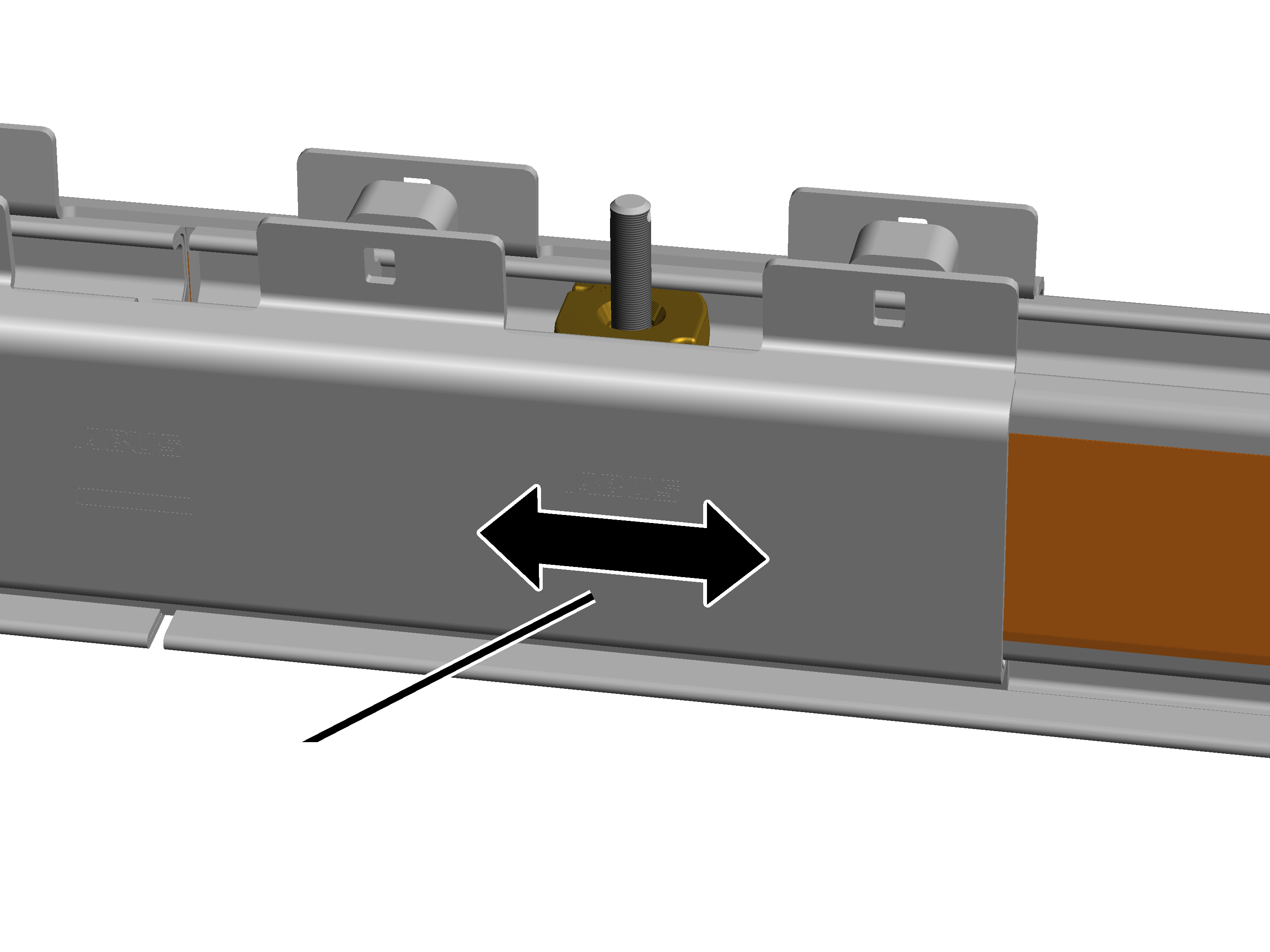
- Only with a craneway suspension in the area of a clamping plate: the clamping plates can be shifted up to 100 mm.
Screwing in the assembly screw
The assembly screw (which is longer than the actual screws) is used to pull the clamping plates to the HB profile rail so that the actual screws can be inserted.
- Check the spacing of the profile rail sections again.
The profile rail sections can be directly flush to one another. The must not be more than 2 mm apart.
Assembly aids
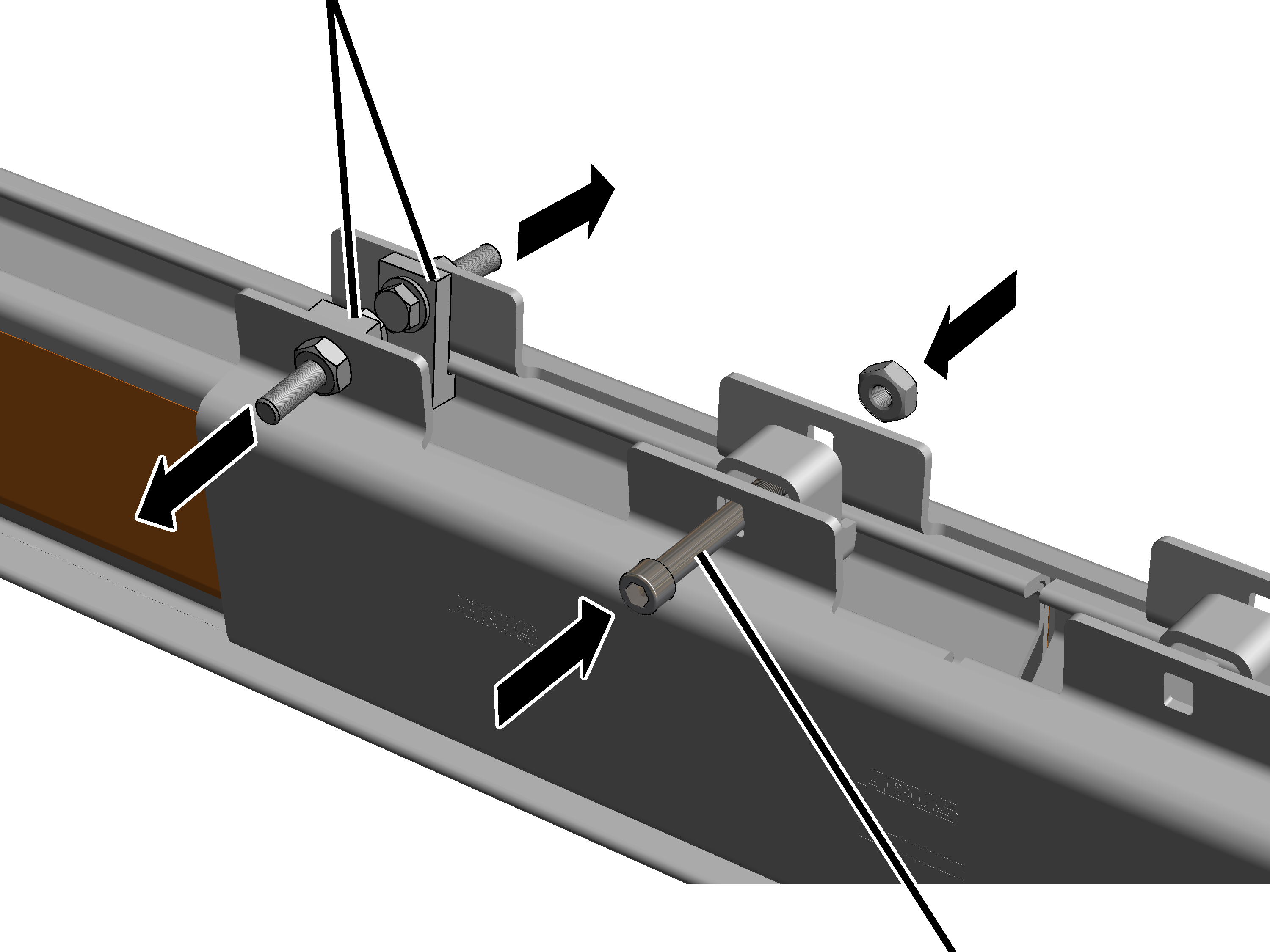
- Insert the M12x95 assembly screw through two opposite-lying brackets of the clamping plate.
- Screw a hexagonal nut onto the assembly screw.
- Continue screwing the assembly screw and hexagonal nut together to pull the clamping plates to the HB profile rail from both sides.
- Once the assembly screw is screwed on: remove the assembly aids (2x).
Screwing the clamping plates tight
On all spacer parts:
Assembly screwHexagonal nut
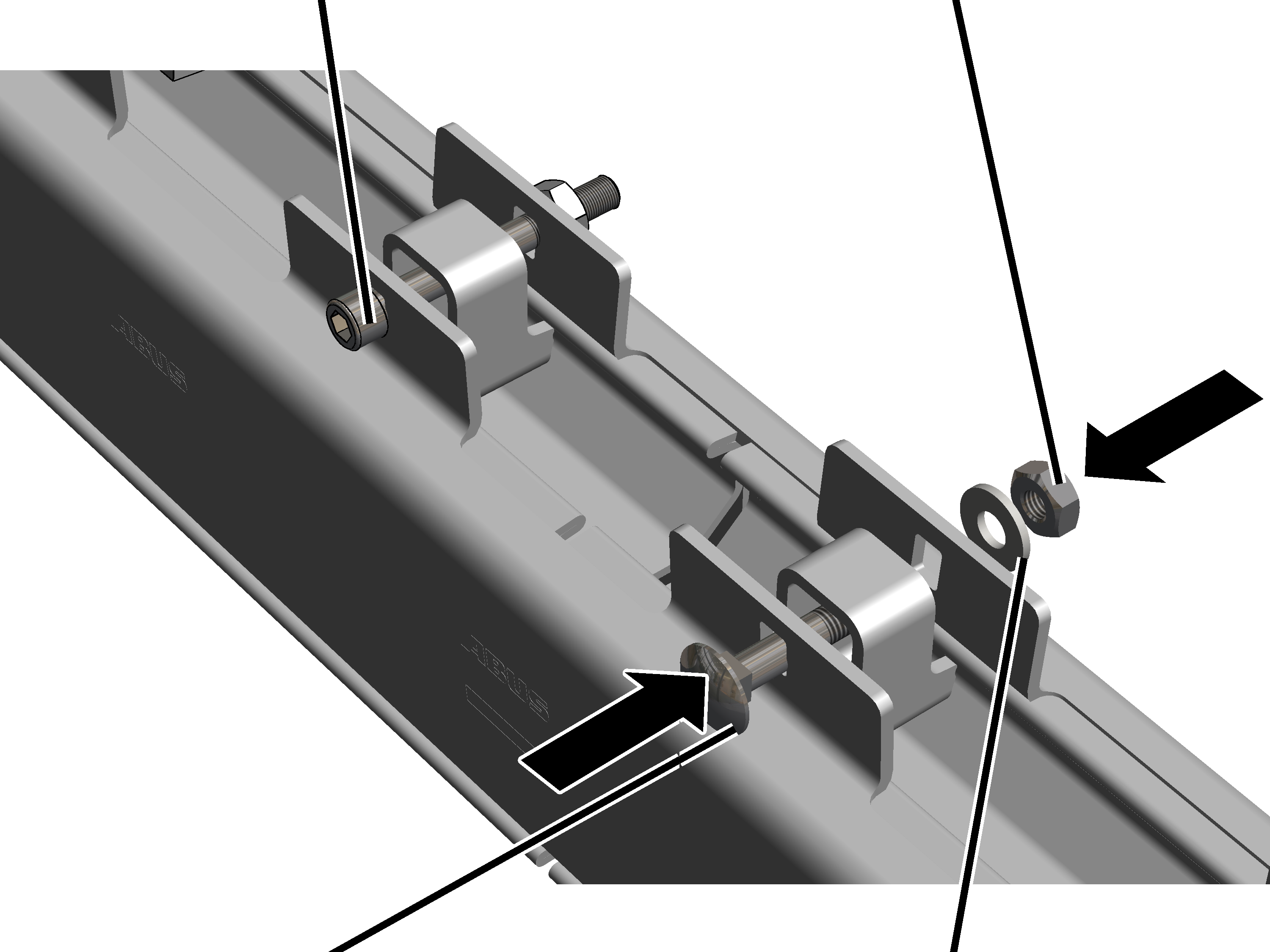
- Push the cup square bolts through the clamping plates and the spacer parts.
Size |
Cup square bolt |
Rating |
|---|---|---|
HB110 |
M12x40 |
12.9 |
HB150 |
M12x60 |
12.9 |
HB190 |
M12x60 |
12.9 |
HB240 |
M12x60 |
12.9 |
- The square end of the cup square bolt locks in the clamping plate and therefore cannot turn.
- Insert spring washer.
- Loosely screw the M12 hexagonal nut onto the cup square bolt.
- Screw the hexagonal nuts on. Tighten to 120 Nm.
The U-shaped plates included do not have to be installed yet. They are only required if the travel gap is too wide.
Checking the travel gap and distance apart
After the assembly of the clamping plates, check whether the profile rail sections have bent apart.
Travel gap
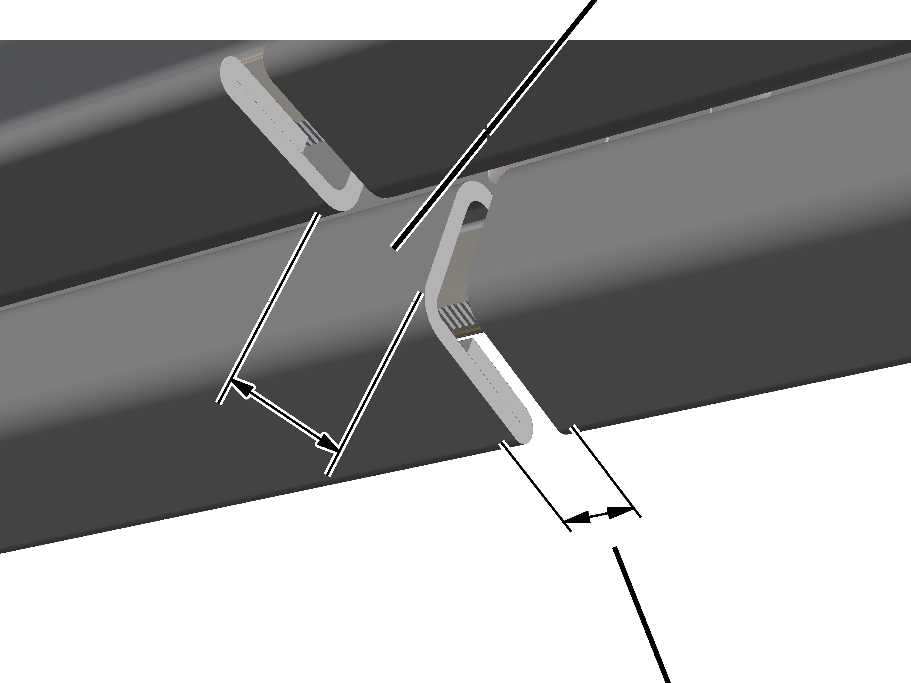
- Check the travel gap in the area of the profile joint:
- The travel gap is permitted to be maximally 25 mm wide.
- The travel gap must be at least 19 mm wide.
- If the travel gap is too wide or too narrow: press the profile rail section together with a screw clamp or use a suitable lever to press it apart.
- Check the spacing of the profile rail sections.
The profile rail sections can be directly flush to one another. The must not be more than 2 mm apart.
Only with HB110, HB150 and HB190
If the travel gap is still wider than 25 mm:
The enclosed U-shaped plates can be inserted in addition to the spacer parts to reduce the travel gap.
Spacer part
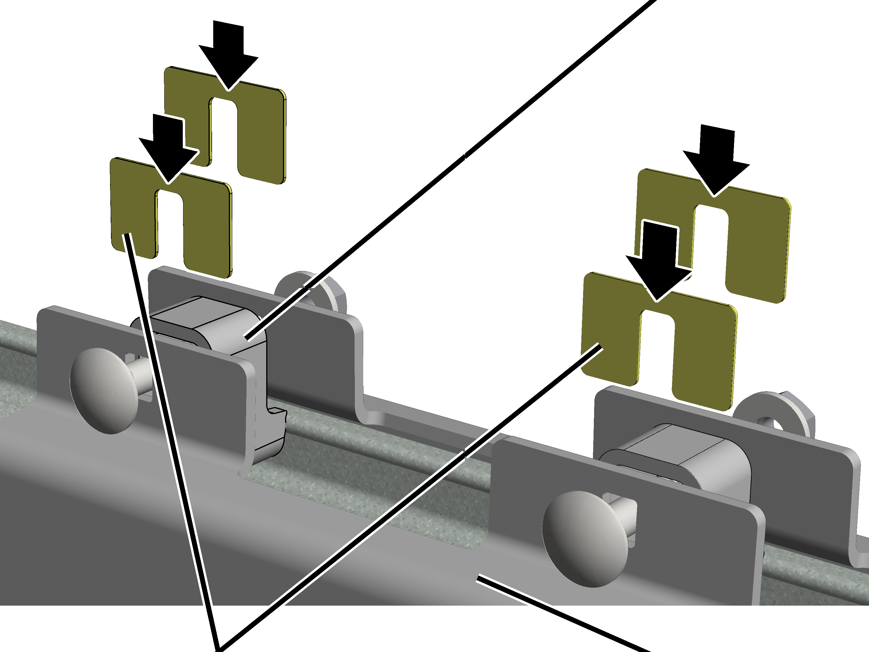
- Slightly loosen all hexagonal nuts on the cup square bolts.
- The clamping plates (2x) move apart at the top at the spacer parts.
- Insert a U-shaped plate from above on the left and right next to all spacer parts.
The plates always have to be inserted on the left and right and always on all four spacer parts.
The plates must be inserted until they are flush with the top edge of the spacer parts.
- Screw the hexagonal nuts on. Tighten to 120 Nm.
- The plates keep the clamping plates on the profile head somewhat further apart. Thus the profile rail sections at the travel gap will not bend as far apart.
- Check the travel gap again.
Connecting aluminium profile rail sections
Depending on the length of the individual profile rail sections, the number of suspensions, the on-site building conditions and the length of the crane track, several profile rail sections should be connected with each other on the floor if possible.
The connected profile rail sections must be able to be raised and brought underneath the suspensions safely and without posing additional hazards.
If this is not possible, the profile rail sections must first be fixed individually or as sections on the suspension and then afterward fully joined with each other. When doing this, it must be ensured that there is adequate space underneath the suspensions, especially in the case of short suspensions.
Laying out the profile rail sections
- The profile rail sections must be laid out on the building floor the way they are to be later installed.
The specified dimensions, positions and clearances must be followed exactly.
Removing the protective film
The profile rail sections are laminated at the sides. The protective film is removed before further assembly.
Protective film
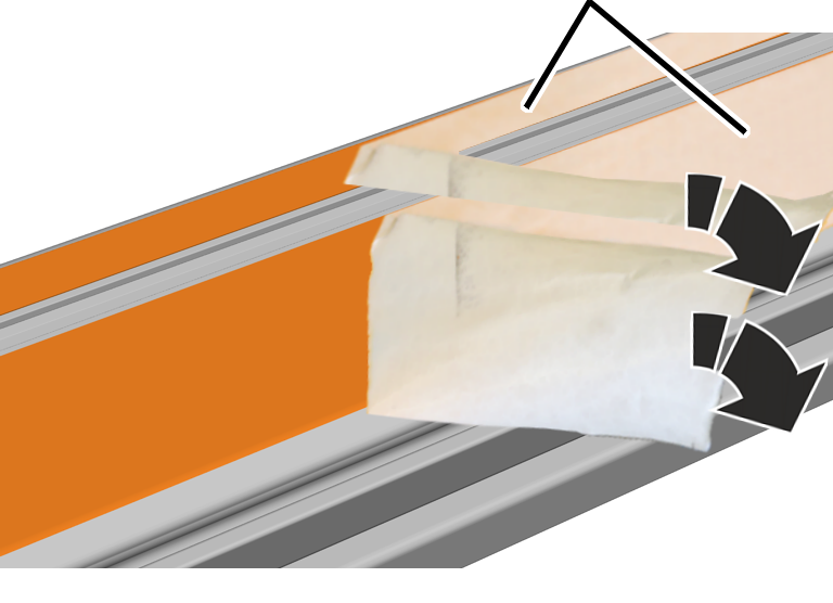
- Pull off the protective film at a sharp angle from the side lamination.
Inserting head nuts
Head nut
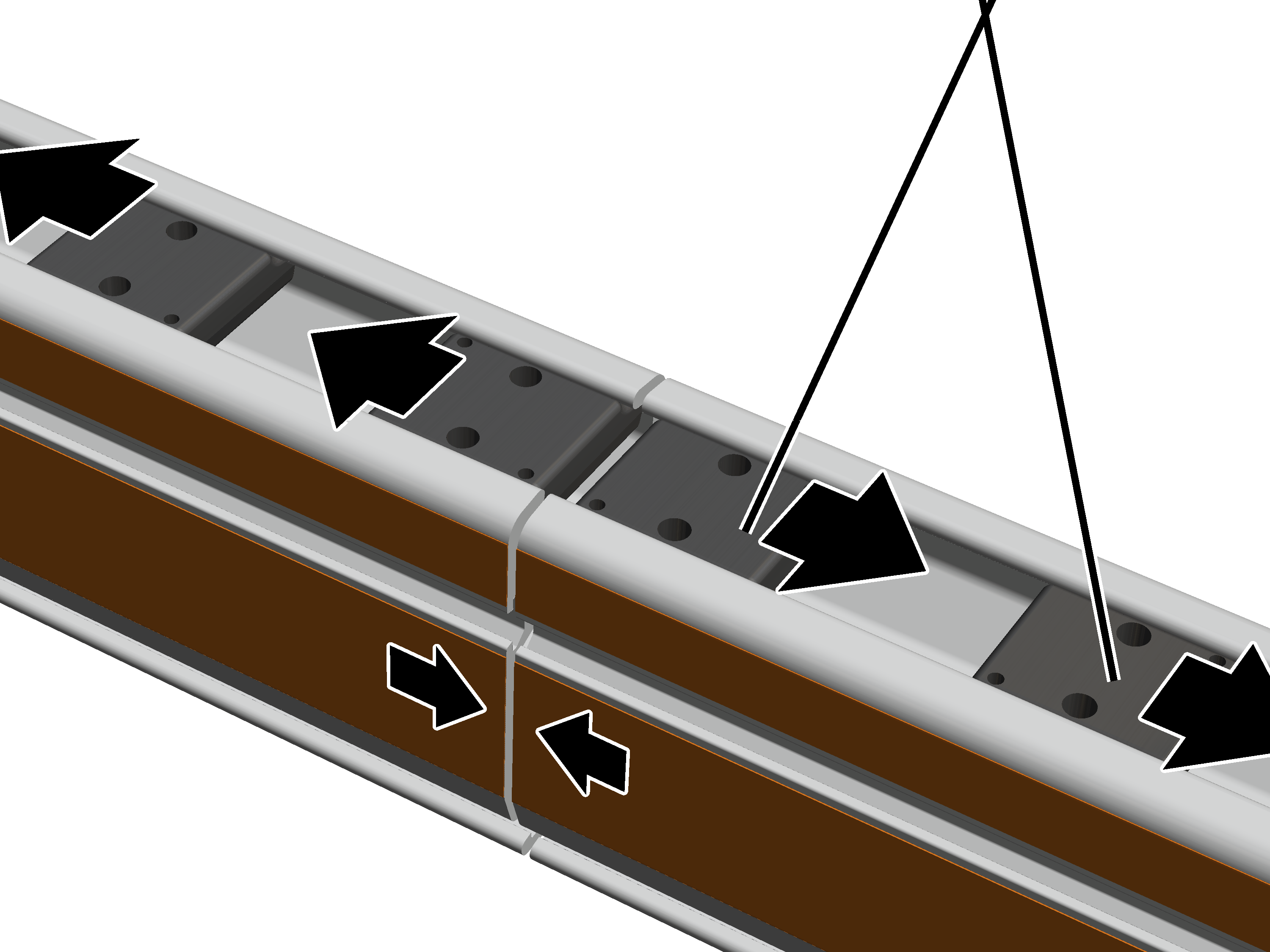
- Insert two head nuts each in the left and right profile rail sections.
In the case of connection with one curved section: only one head nut each is inserted into the left and right profile rail section.
- Lay the profile rail sections together.
The profile rail sections can be directly flush to one another. The must not be more than 2 mm apart.
Only with a craneway suspension in the area of a profile joint
This work step only applies if a suspension will be installed in the area of a profile joint.
Inserting the profile link
Before the clamping plates are inserted:
Profile jointBearing shell
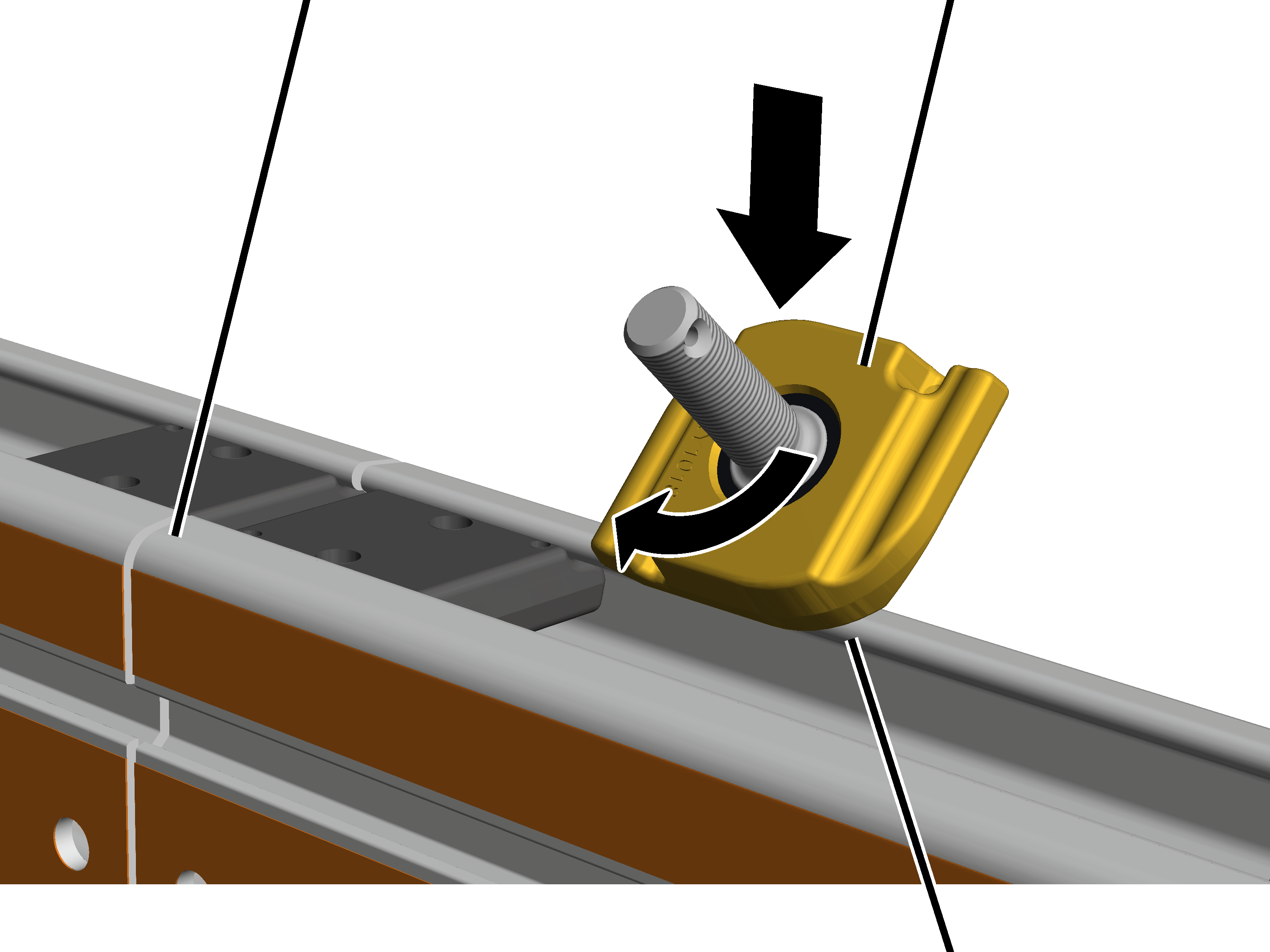
- Tilt the profile link and insert it from above at the required point in the profile head.
Once the clamping plate is installed, the profile link can no longer be shifted at will.
The bearing shell in the ceiling-mounted bracket and on the profile link must always have the same colouring (silver or yellowish). Ceiling-mounted brackets and profile links with differently coloured bearing shells should not be installed together.
- Turn the profile link 90 .
Inserting the clamping plate
Clamping plates
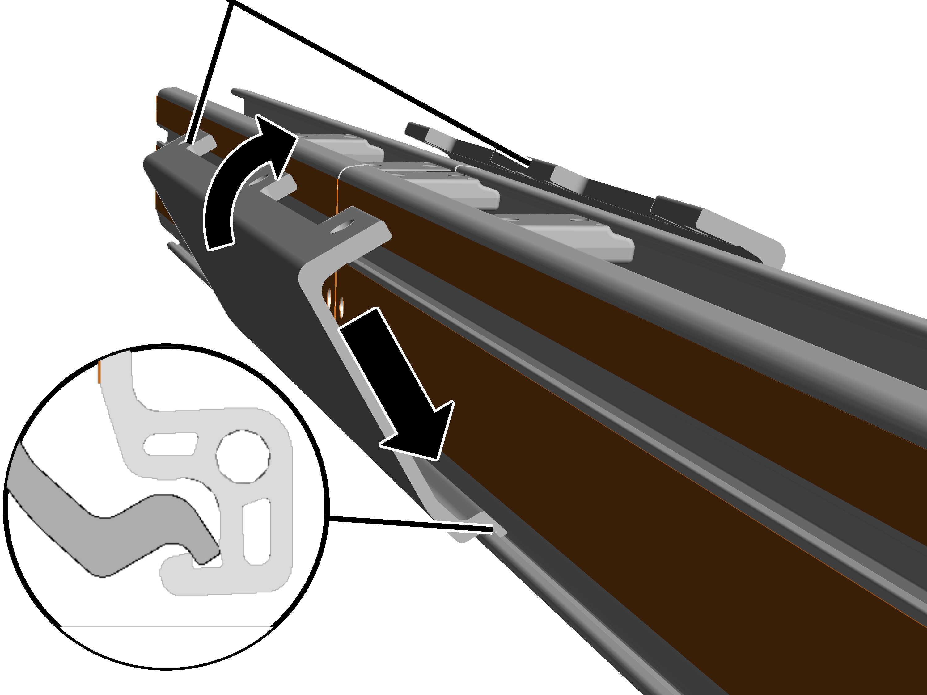
- Tilt the clamping plate slightly and insert it below in the profile rail section.
When doing this, insert the bottom of the clamping plate behind the edge on the profile rail section.
- Position the clamping plate so that it is exactly centred between the two profile rail sections.
- Press the clamping plate together at the top.
- At the bottom the clamping plate presses from the inside against the edge of the profile rail section.
Only with a craneway suspension in the area of a clamping plate
This work step only applies if a suspension will be installed in the area of a profile joint.
Positioning the clamping plate
Only with a craneway suspension in the area of a clamping plate: the clamping plates do not need to be inserted exactly centred on the profile joint. The clamping plates can be shifted up to 100 mm to the left or right so that the profile link for the suspension is always at the preferred point.
Note:
For a profile joint without a suspension, the clamping plates must be installed exactly centred!
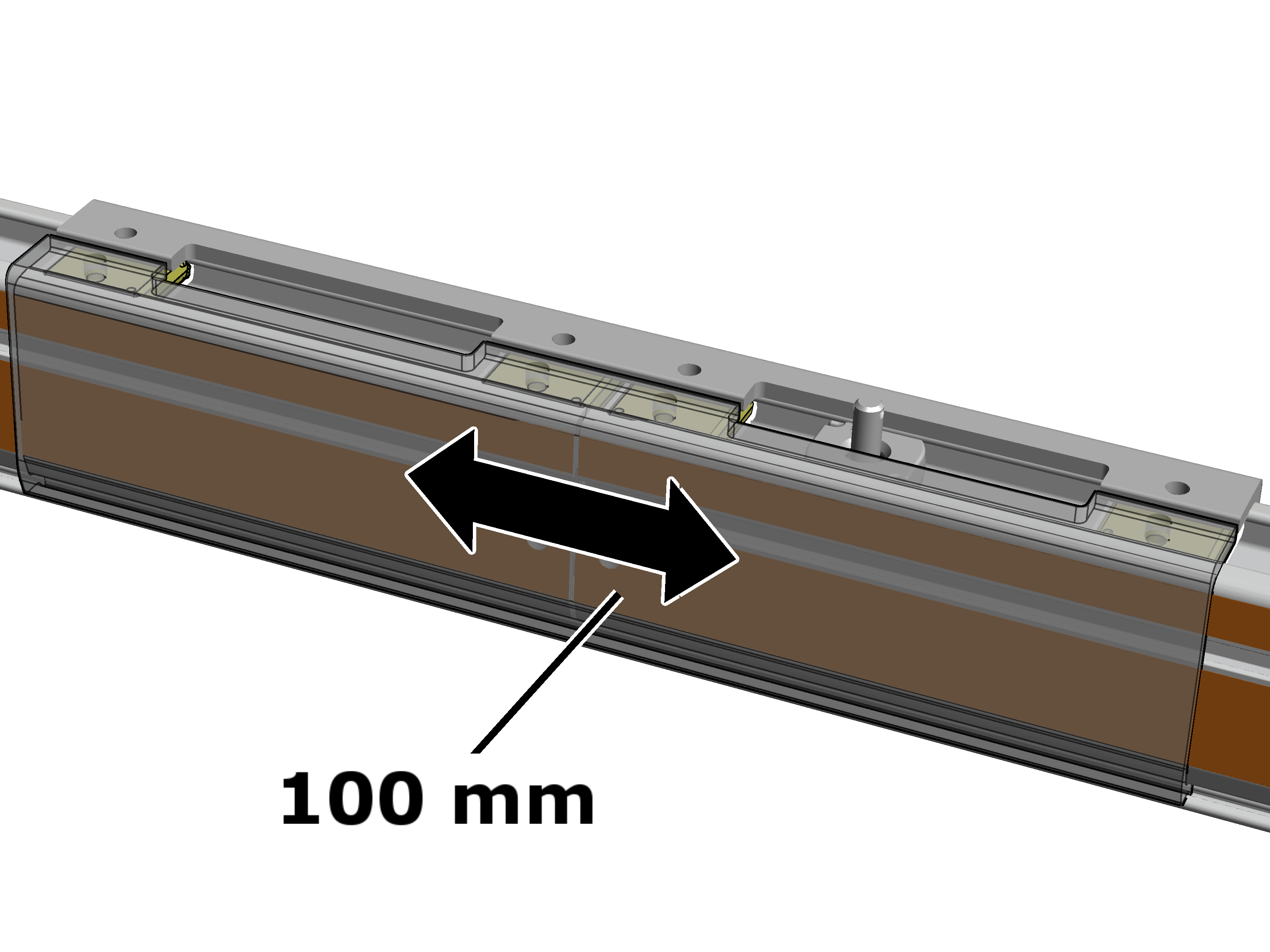
- Only with a craneway suspension in the area of a clamping plate: the clamping plates can be shifted up to 100 mm.
Assembly aid
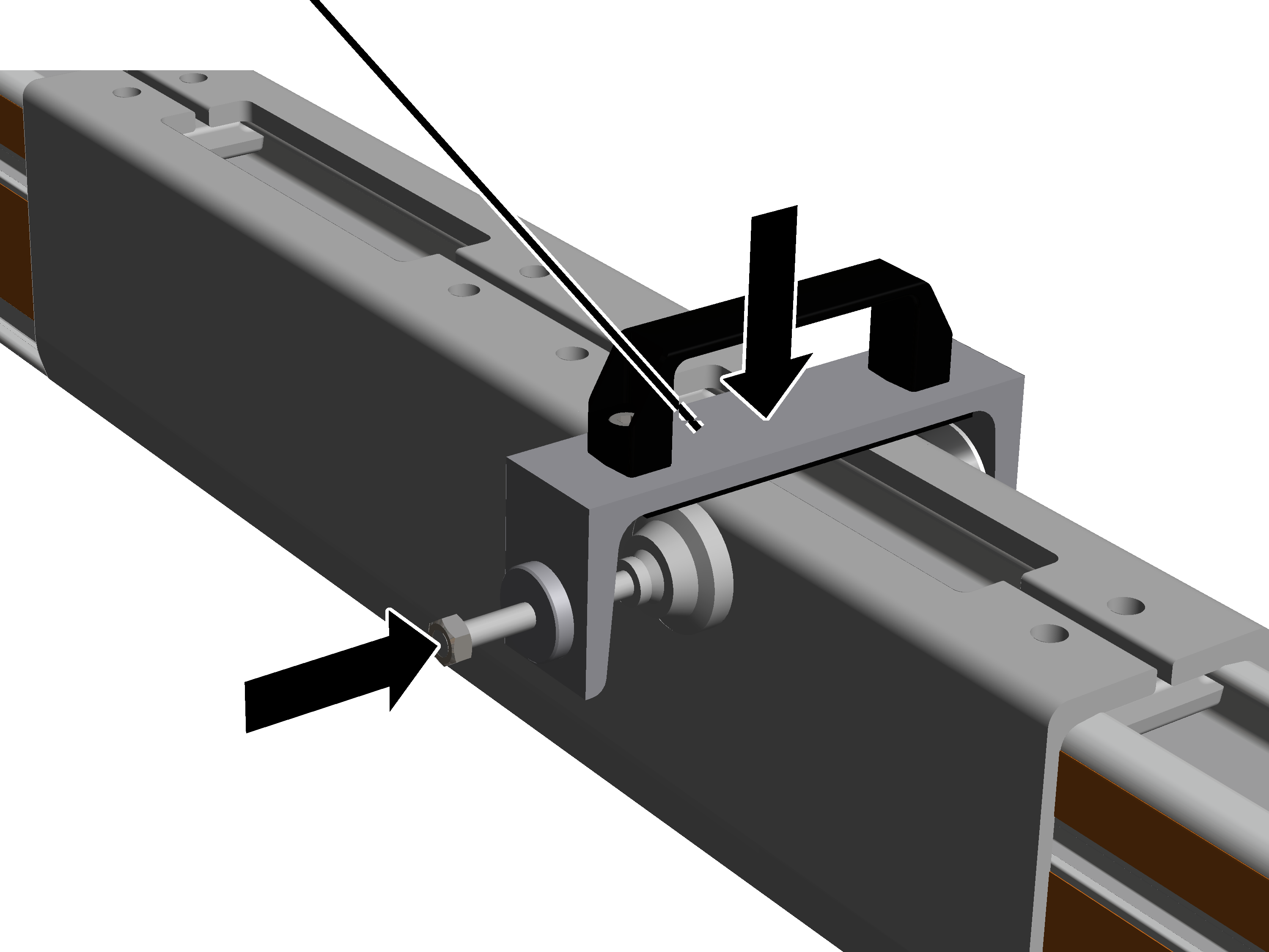
- Press the clamping plates together to such an extent that the assembly aid can be set in place.
- Place the assembly aid on the clamping plate.
The assembly aid can be obtained from ABUS Service. AN 316469.
Alternatively, a screw clamp with suitable base (e.g. rubber mat) can be used.
- Screw the assembly aids together until the clamping plates can clearly be heard to latch into place at the sides.
The clamping plates must be clearly heard to latch in place on both sides and at both profile rail sections.
If necessary: use the assembly aid to press the clamping plates together at the other end as well until they can clearly be heard to latch into place.
Screwing the clamping plates tight
At all four head nuts:
Rib screw M12x50Plate
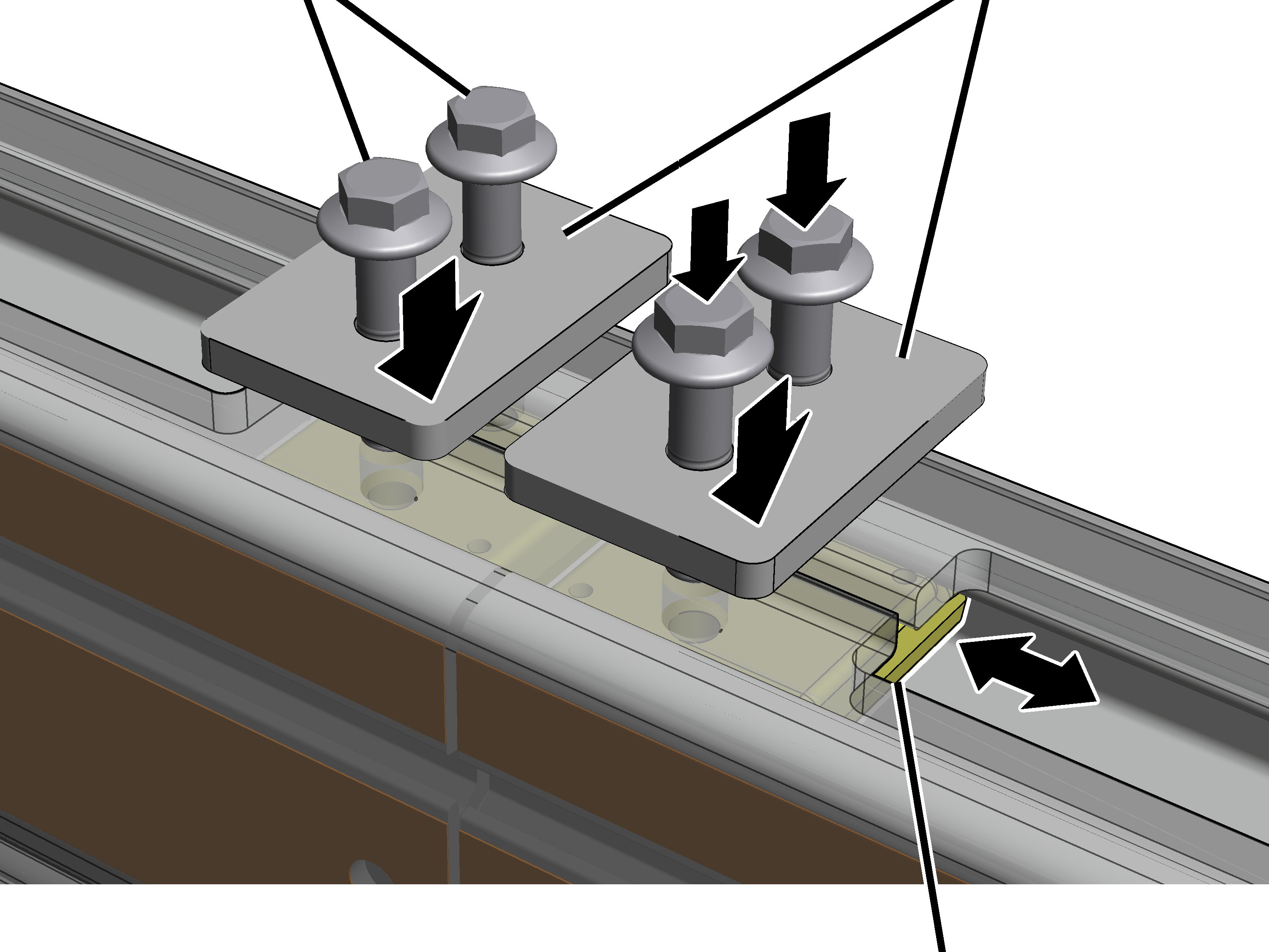
- Position the head nut until it is exactly underneath the clamping plate bracket.
- Place the plate on the drilled holes in the clamping plate.
- Insert the rib screws M12x50 (2x per profile holder) through the plate and the clamping plate and screw into the head nut.
- Screw in the rib screws. 130 Nm.
Sawing profile rail sections
Normally the profile rail sections are cut to the corresponding length for the specific order. This eliminates the need to cut the profile rail sections on-site.
Especially with reconstructions, it may be necessary to shorten the profile rail sections on-site.
Note:
In order for the HB crane or the trolley to later run smoothly and without jolts in the area of a profile joint, high accuracy is required when sawing the profile rail sections. This accuracy can only be achieved with a special sawing fixture.
For this reason, it is only permitted to saw profile rail sections which are mounted at the end of the crane track/crane girder. Profile rail sections may not be cut at a profile joint on-site.
If an existing HB crane installation is expanded, a saw-cut profile rail section at the end of the crane track / crane girder must be disassembled and replaced by a full-length profile rail section. The saw-cut profile rail section can be reinstalled at the end of the expanded HB crane installation.
Only with HB240
Removing crosswise screw fittings
If the profile rail section is to be sawed off near a crosswise screw fitting, the crosswise screw fitting must first be removed.
Crosswise screw fitting
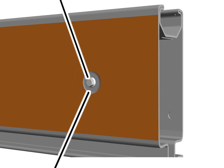
- Check if the saw cut is in the area of a transverse screw connection.
If sawing must be performed near the level inner surface of the bead, the crosswise screw fitting must be removed.
If sawing is performed in the inclined area of the bead, the crosswise screw fitting can remain mounted.
Rib nut M8
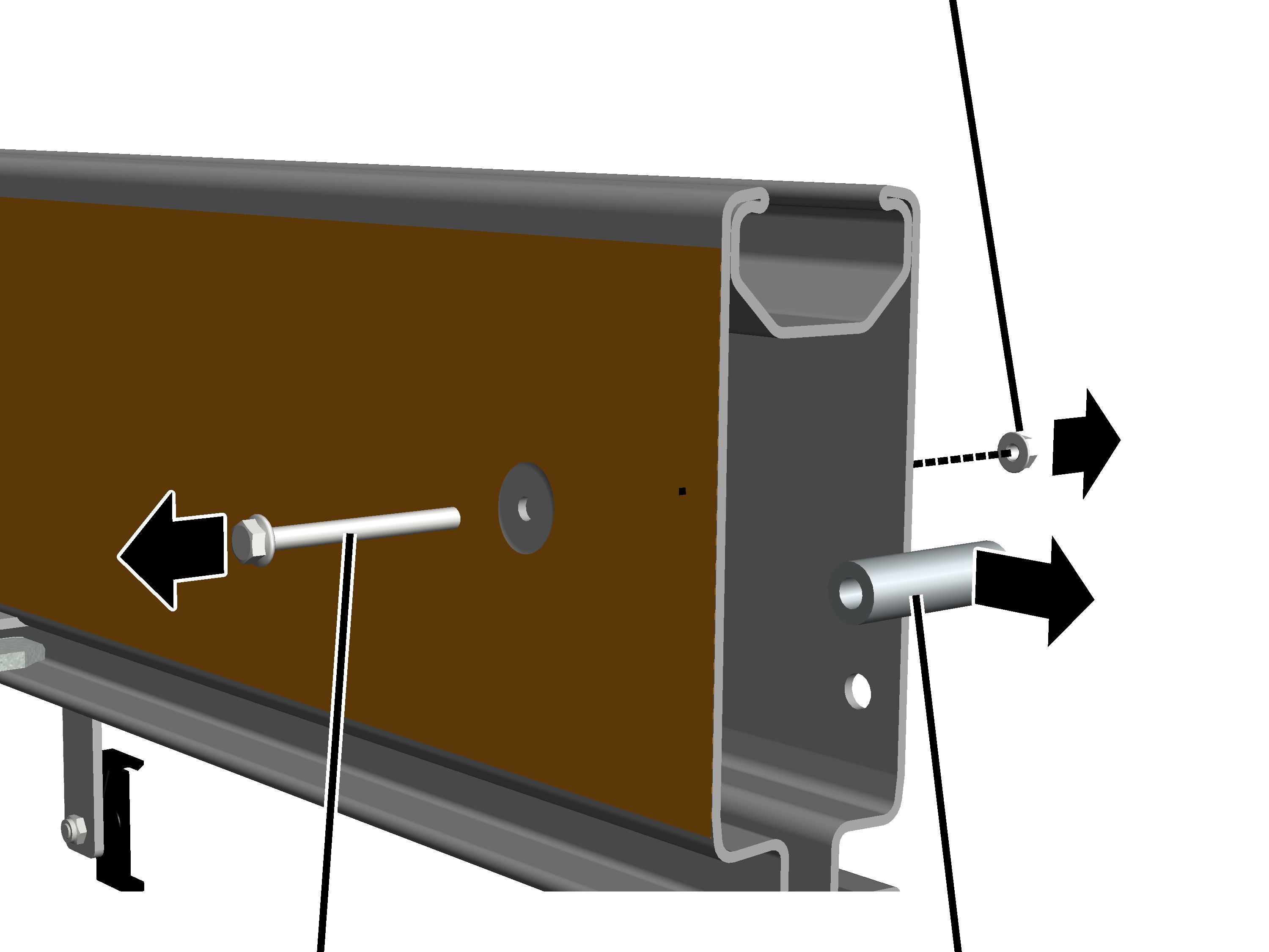
- Remove the film on both sides of the bead to reach the rib screws and rib nuts.
- Release rib screw M8x80 and rib nut M8.
- Remove the spacer sleeve from the HB profile rail.
Rib screw, rib nut and spacer sleeve are no longer needed.
Sawing the profile rail section
Sawing a profile rail section at the beginning or end:
Distance to cut edge 20 mm
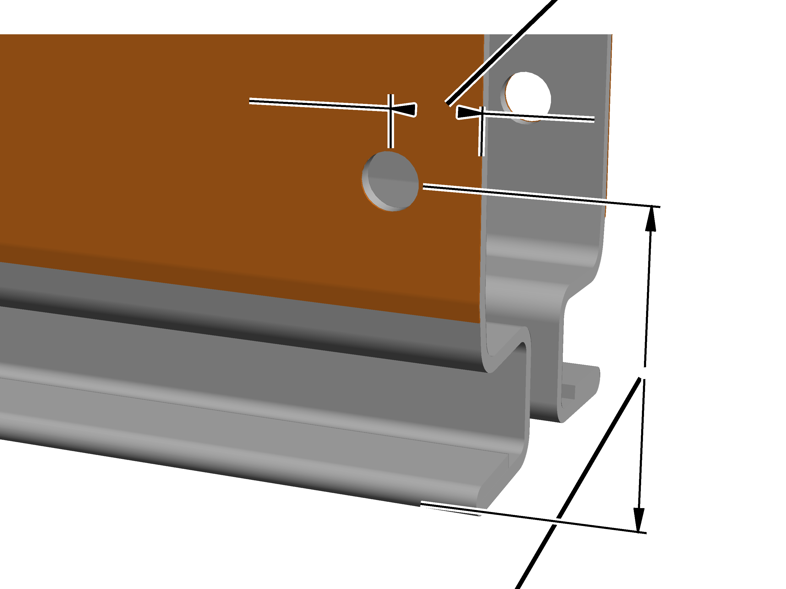
- Turn the profile rail section so the opening is facing down.
This allows shavings to fall out of the profile rail section so they do not accumulate inside it.
- Saw off the profile rail section at a perpendicular angle at the desired point.
- Drill a hole in the profile rail section on both sides for the end cap.
- Diameter 13 mm.
- 20 mm from the sawed edge
- Distance to lower edge
Size |
Distance |
|---|---|
HB110 |
48 mm |
HB150 |
73 mm |
HB190 |
73 mm |
HB240 |
73 mm |
- Deburr the drilled holes.
Running surface
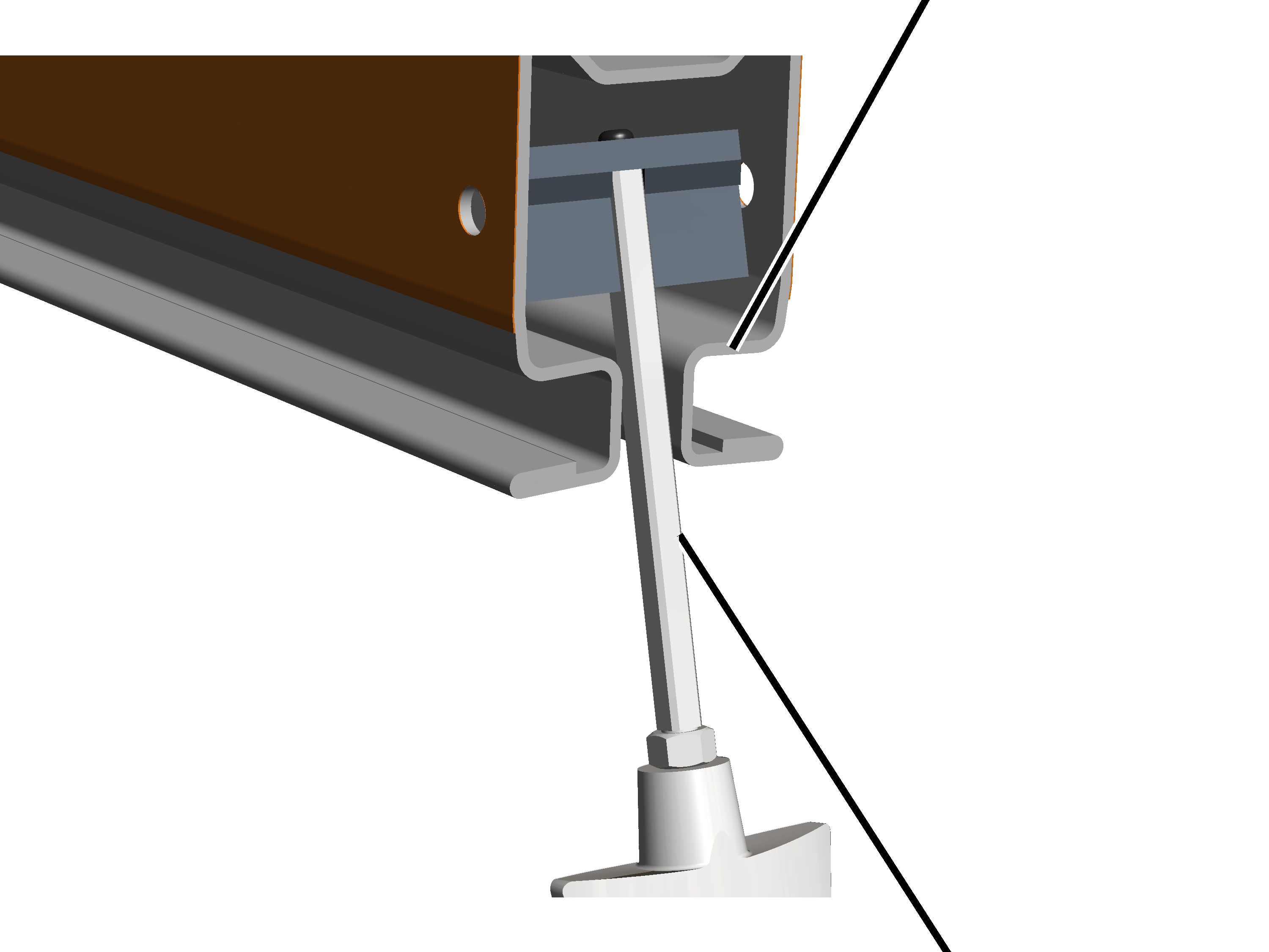
- Remove any saw or drill shavings on the inside; particularly from the running surface at the travel gap.
Otherwise the shavings can clog the castors of the trolleys and impair their running.
A special brush can be used for the simple and effective cleaning of the running surface. The brush can be obtained from ABUS Service. AN 315909. See “ABUS Service”.
Installing profile connections for craneway suspension M16
Now the profile connections are mounted in the profile head. The profile connections are used to later hang the crane track on the suspensions.
Installing the profile connection
For every suspension:
- Refer to the planning documents for the points intended for the profile connections. The specified dimensions, positions and clearances must be followed exactly.
Only with a suspension on a free profile rail section
This work step only applies if a suspension is to be installed in the free running area of the HB profile rail. This is the most common case.
Profile connectionTension nut
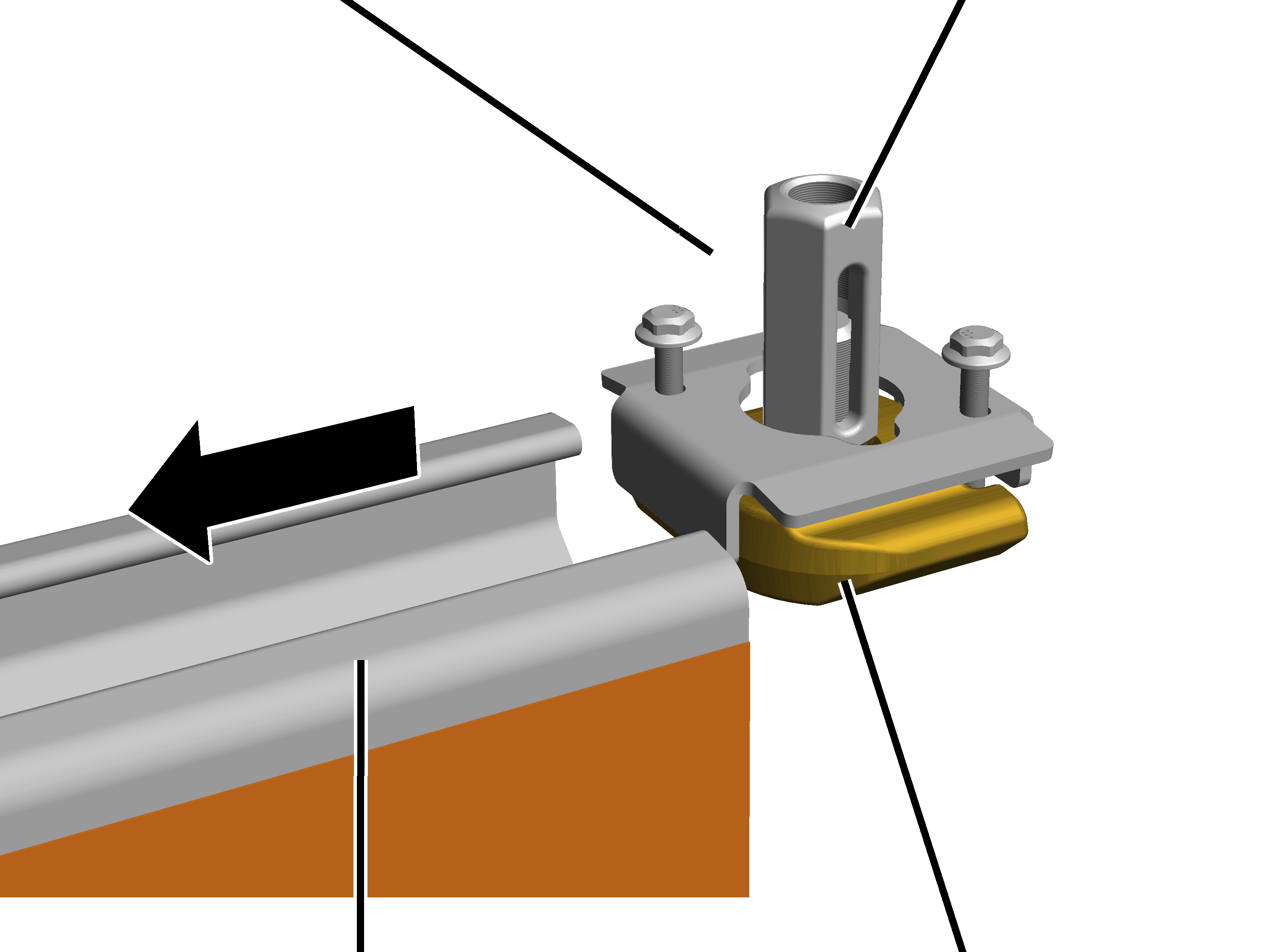
- Insert the profile connections in the profile head and move them up to the points specified in the planning documents.
The bearing shell in the ceiling-mounted bracket and on the profile link must always have the same colouring (silver or yellowish). Ceiling-mounted brackets and profile links with differently coloured bearing shells should not be installed together.
Rib screw M6x40
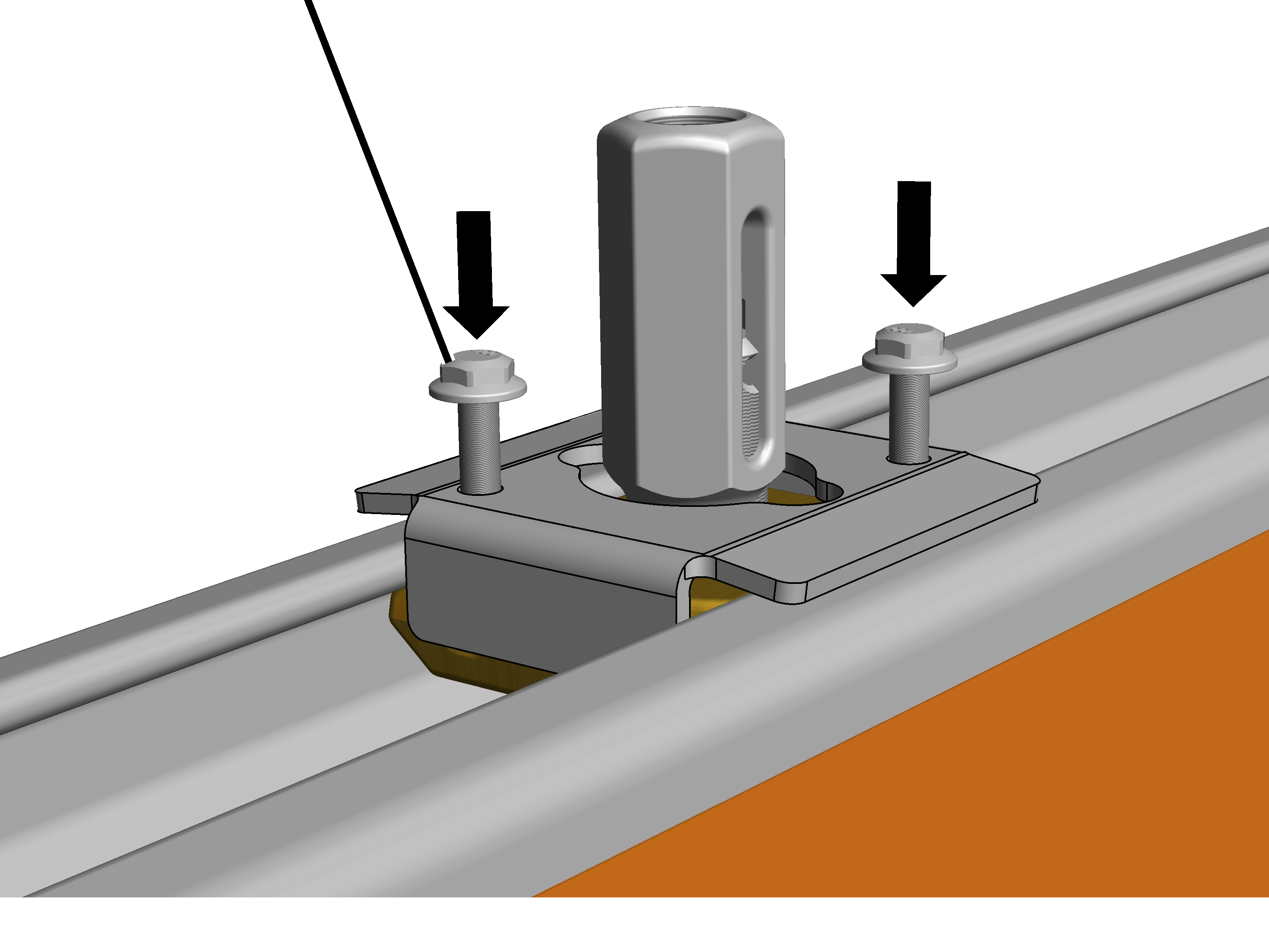
- Screw in the M6x40 rib screws (2x) two to three revolutions. Do not yet screw them tight.
Only with a craneway suspension in the area of a clamping plate
This work step only applies if a suspension will be installed in the area of a profile joint.
Rib screws M6x40
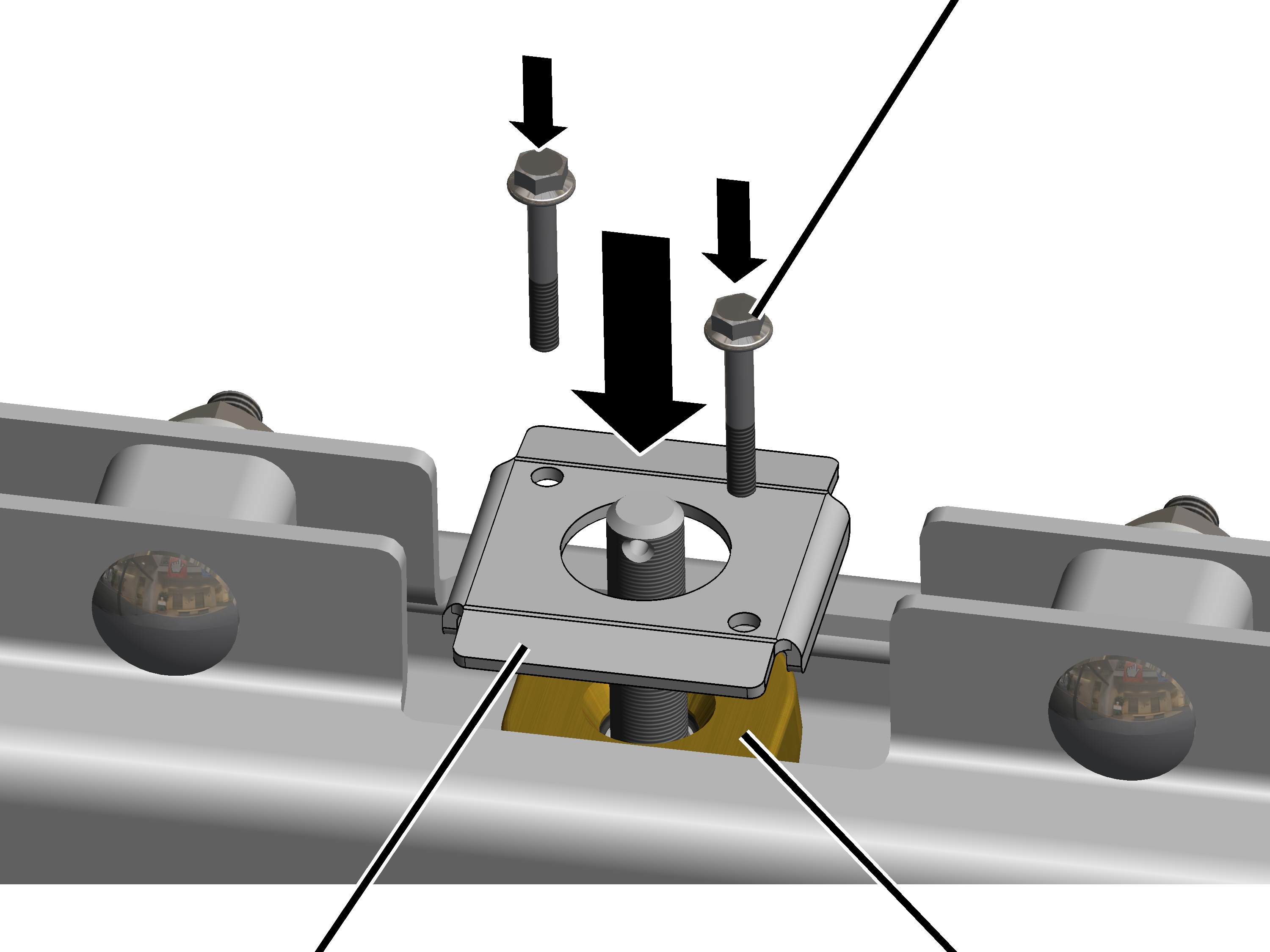
- Place the retaining cap on the profile link.
- Insert the M6x40 rib screws (2x) through the retaining cap and screw them in two to three revolutions. Do not yet screw them tight.
Releasing tension nuts
Only with normal suspension
In order for the profile connection to later be easily mounted on the suspension, the tension nuts must be released.
Tension nut
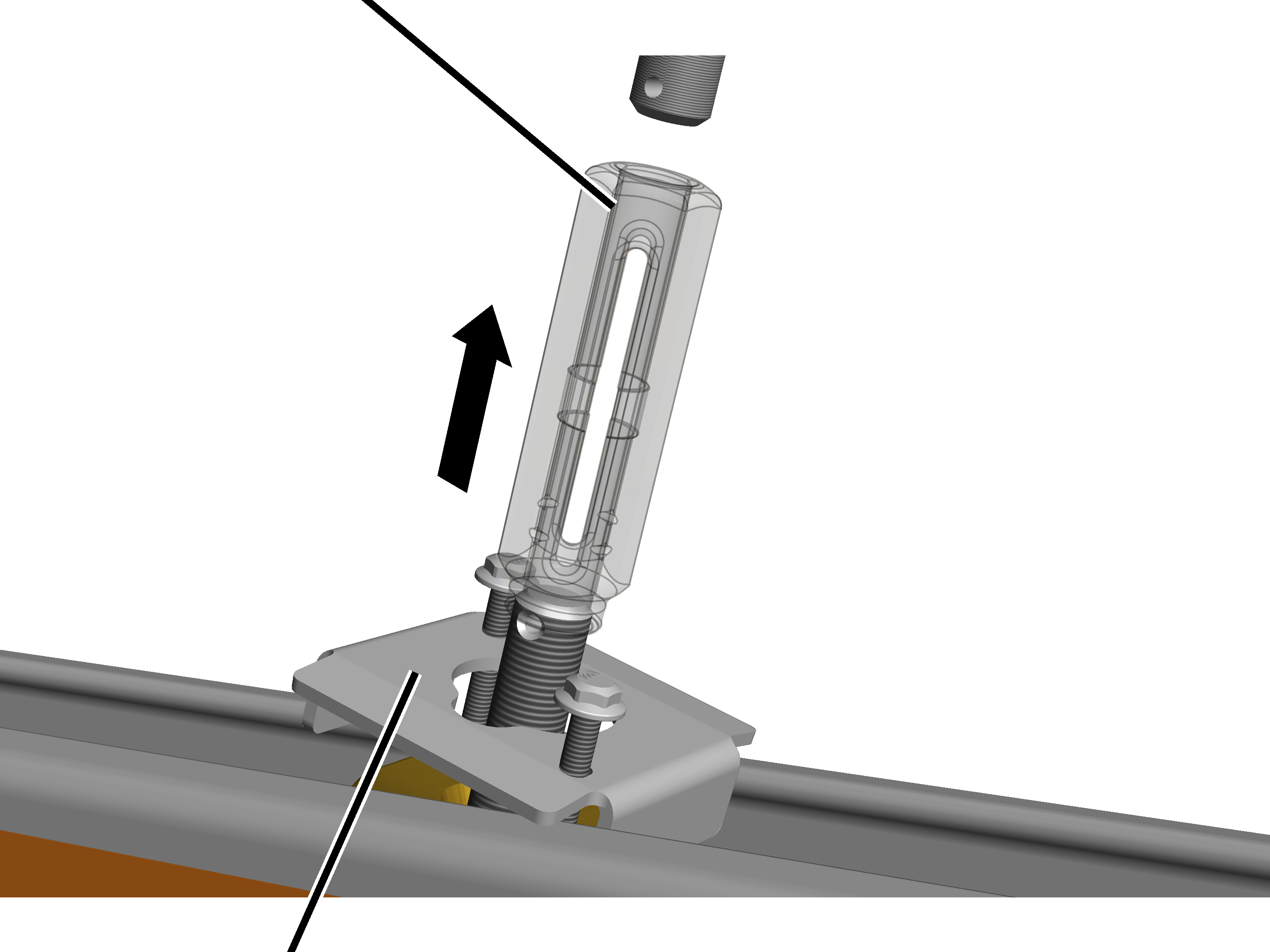
- Unscrew the tension nut almost completely from the threaded rod of the profile connection.
Leave the tension nut screwed on the profile connection by one or two thread turns.
The undercut on the long tension nut does not need to be heeded in combination with the normal suspension.
- Do not yet tighten the rib screws M6x40 (2x).
Only for short suspension XS and S
In order for the profile connection to later be easily mounted on the suspension, the tension nuts must be released.
Tension nut
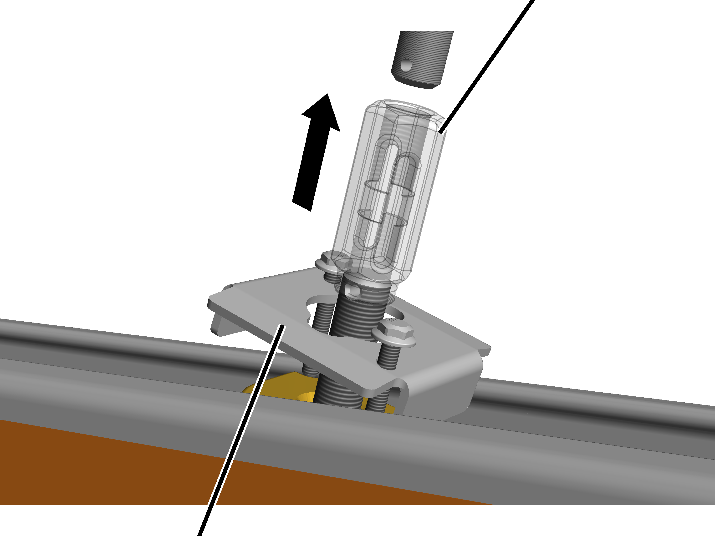
- Unscrew the tension nut almost completely from the threaded rod of the profile connection.
Leave the tension nut screwed on the profile connection by one or two thread turns.
- Do not yet tighten the rib screws M6x40 (2x).
Only for short suspension M and L
In order for the profile connection to later be easily mounted on the suspension, the tension nuts must be released.
The long tension nut should not be unscrewed too far on the threaded rod of the profile connection.
Tension nutUndercut
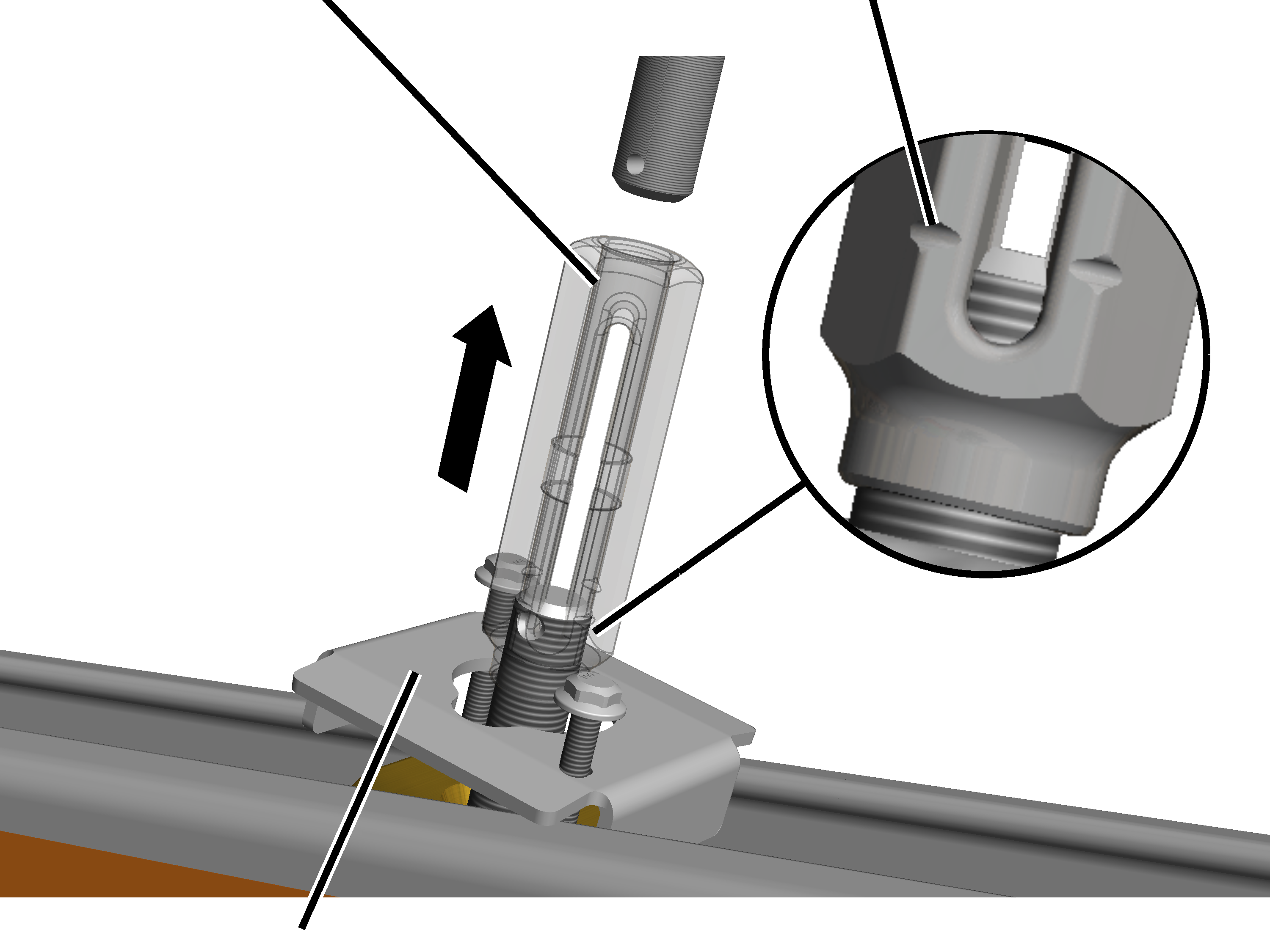
- Screw the long tension nut onto the threaded rod of the profile connection until it is at the undercut.
Attaching ABUS manufacturer labels
Before installing the HB crane runway on the craneway suspensions, stick the ABUS manufacturer labels on the HB crane runway HB profile rails.
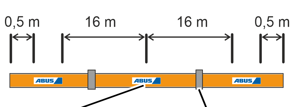
- On each profile rail section an ABUS manufacturer label is provided on each side.
- For the ABUS manufacturer labels at both ends of the HB crane runway, measure a distance of 0.5 m for both. Position all other ABUS manufacturer labels at a 16 m distance along the HB crane runway on both sides of the HB profile rails.
The layout should be symmetrical to the length of the runway.
- Depending on the on-site conditions in the building (e.g. length of the entire HB crane runway, visibility of the profile rail sections, length of sections), the exact position of the ABUS manufacturer labels can be optimised individually.
ABUS manufacturer label
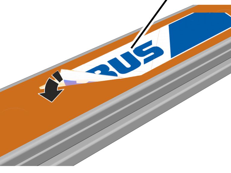
- Pull off the protective foil and adhere the ABUS manufacturer label horizontally on the HB profile rail.
Only on HB240 without lamination:
The beads in the HB profile rail can be covered over when doing this. Each ABUS manufacturer label covers two beads.
Installing the HB crane runway on the M16 craneway suspension
Now the prepared crane track can be fitted to the already installed suspensions.
Depending on the length of the individual profile rail sections, the number of suspensions, the on-site building conditions and the length of the crane track, the crane track can be installed complete or in sections, and then connected up on the suspensions in a hanging position.
Dependent on this, the mains power supply can also be installed before or after the installation of the crane track.
Raising the crane track under the suspensions
Threaded rod of the suspension
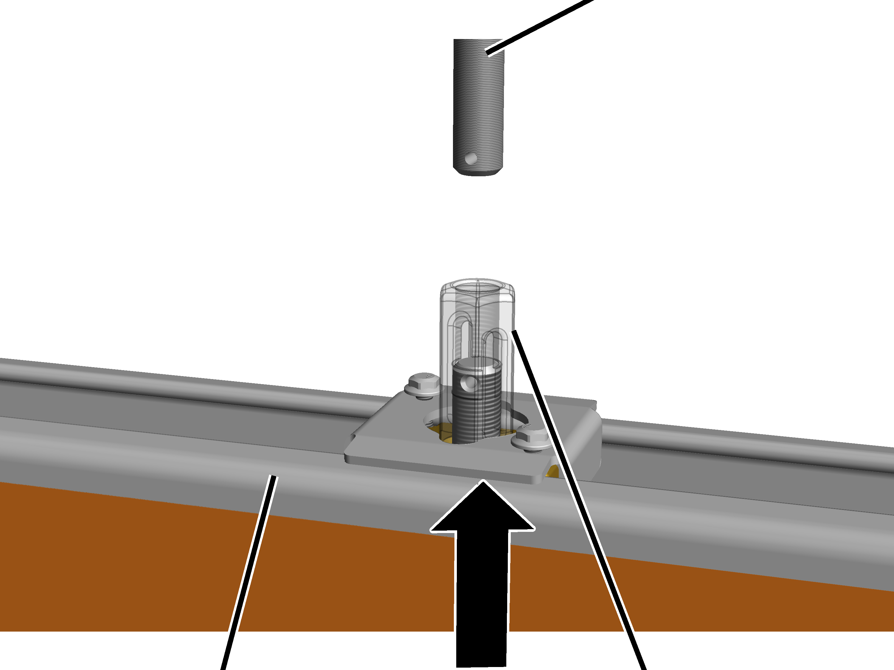
- Fasten the preassembled crane track or sections of crane track to the hoist (e.g. forklift, crane, etc.).
The crane track must be secured against tilting and slipping.
- Observe occupational health and safety requirements and lift the crane track.
- Raise the crane track with the tension nuts under the suspension. Do not press the tension nuts into the threaded rod while doing this!
Fixing the crane track
Tension nut
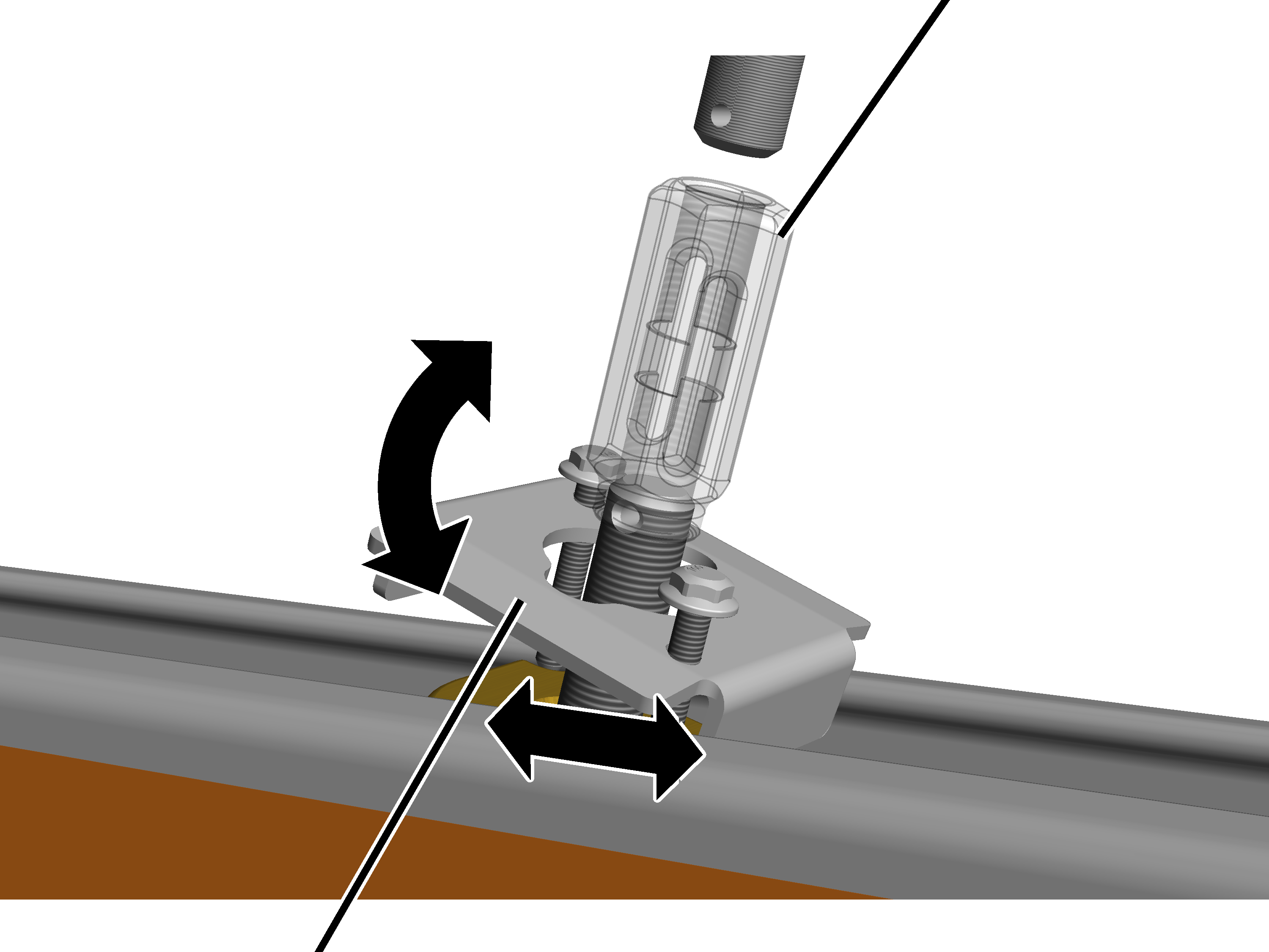
- Bring the tension nut exactly under the suspension.
Since the profile connection is not yet screwed tight, it can be shifted for precise alignment in the profile head. If necessary, the profile connection can also be tilted in the profile head.
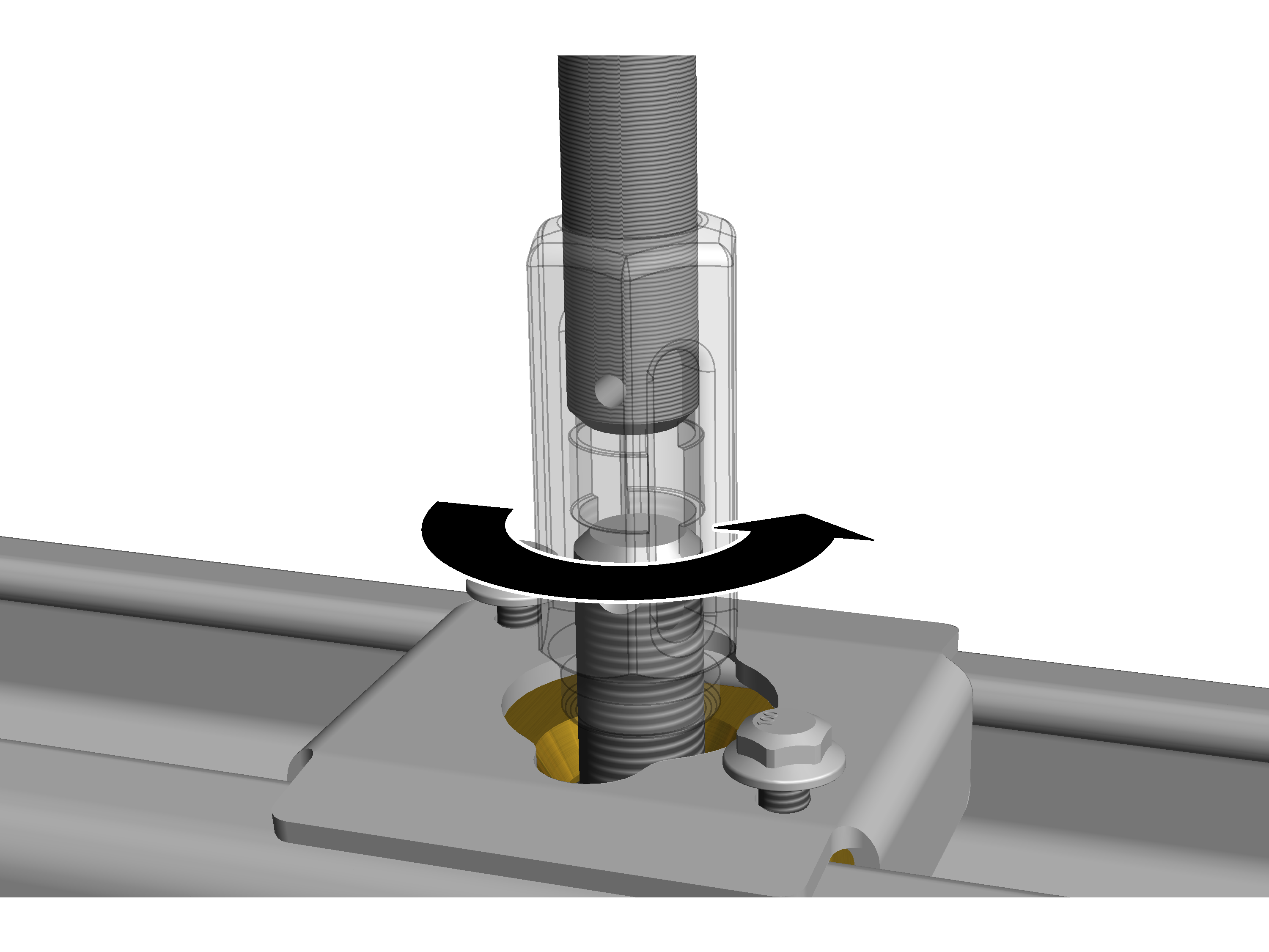
- Screw the suspension and profile connection together with the tension nut.
The tension nut has a left-hand/right-hand thread. This enables the crane track to be pulled toward the suspension.
Aligning the crane track
Now the crane tracked will be aligned. The better the alignment of the crane track, the longer the service life of the trolleys and the better the running characteristics of the HB crane.
Checking the position of the crane track
- Check the alignment of the crane track using a spirit level or hydrostatic level.
The tolerance of the crane track must meet the following criteria:
Height of a crane track runway:
Maximum height differenceSuspension
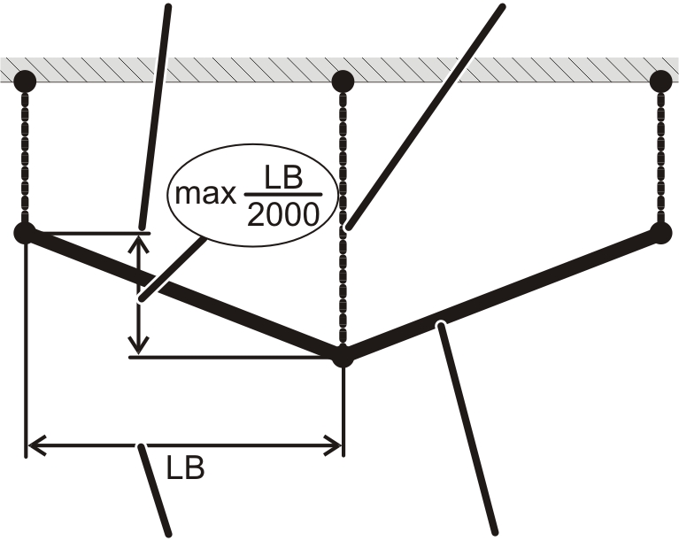
- Suspension distance LB in mm.
- Maximum height difference between two suspensions = LB / 2000
Deviation of span:
Maximum spanMinimum span
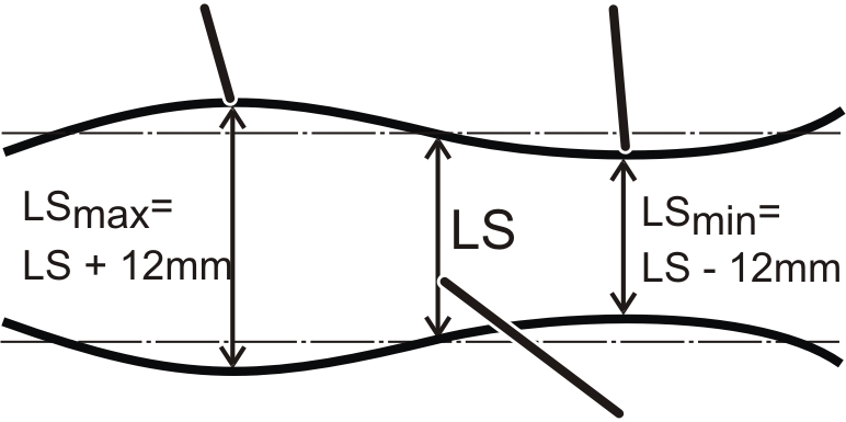
- Span LS in mm.
- Maximum span (LSmax) = LS + 12 mm.
- Minimum span (LSmin) = LS − 12 mm.
Height difference between two tracks:
Span LS
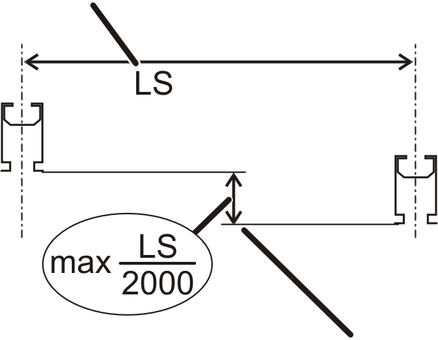
- Span LS in mm.
- Maximum height difference between two tracks = LS / 2000
Setting the position of the crane track
Correcting the height:
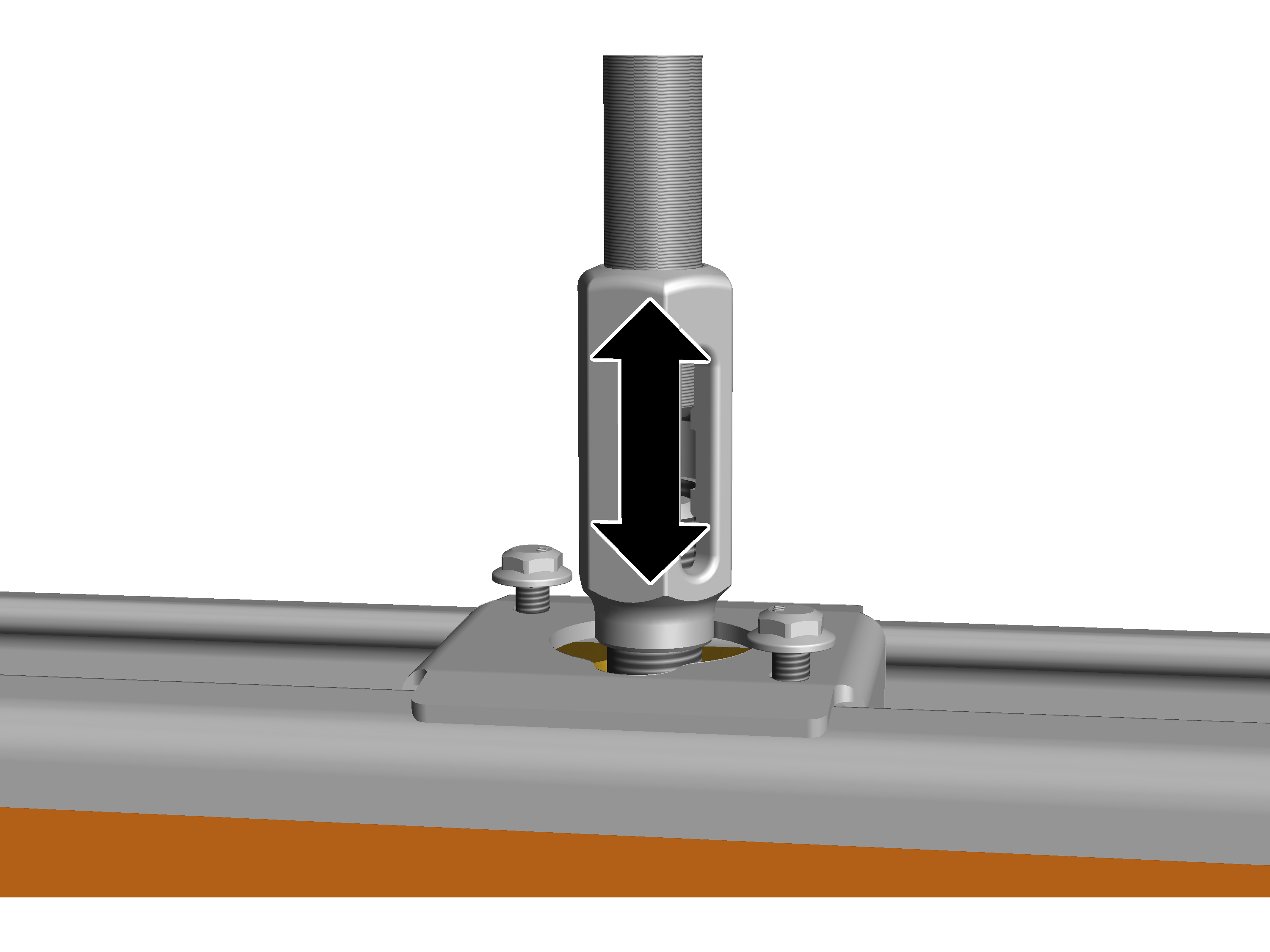
- Turn the tension nut to adjust the height.
The tension nut can be used to alter the height by maximally 20 mm (+/- 10 mm).
Adjusting the span:
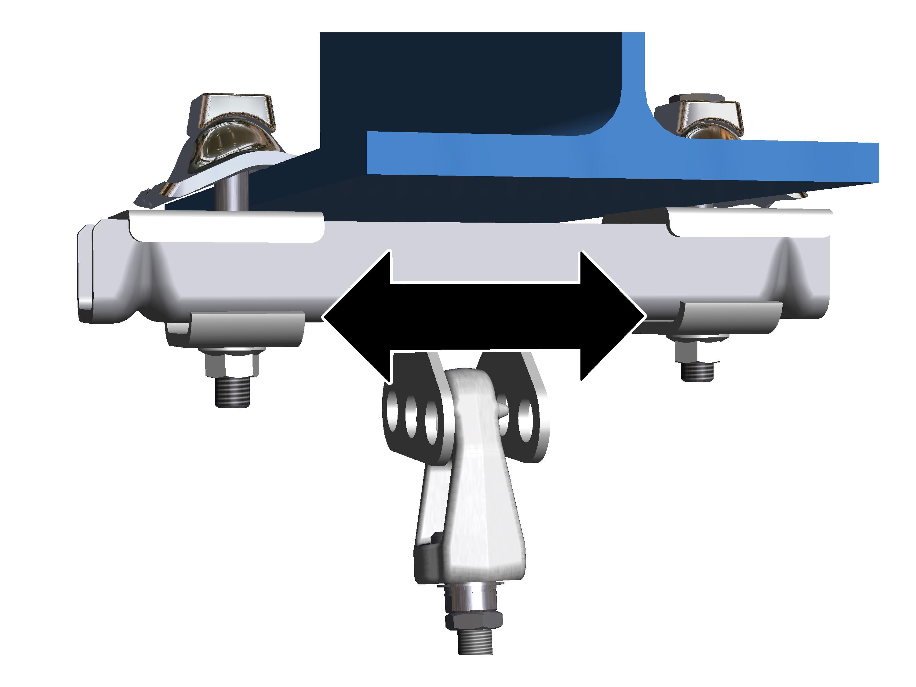
- To adjust the span, shift the ceiling-mounted bracket 2LP/M16 or M20 to the left or the right in the elongated holes.
Inspecting craneway suspensions
- Check all threaded rods.
The position of the threaded rods must meet the following criteria:
Threaded rod plumb-vertical
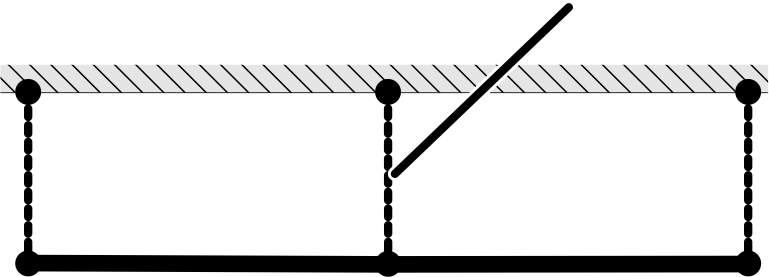
- The threaded rods must be aligned plumb-vertical.
Gap in profile head
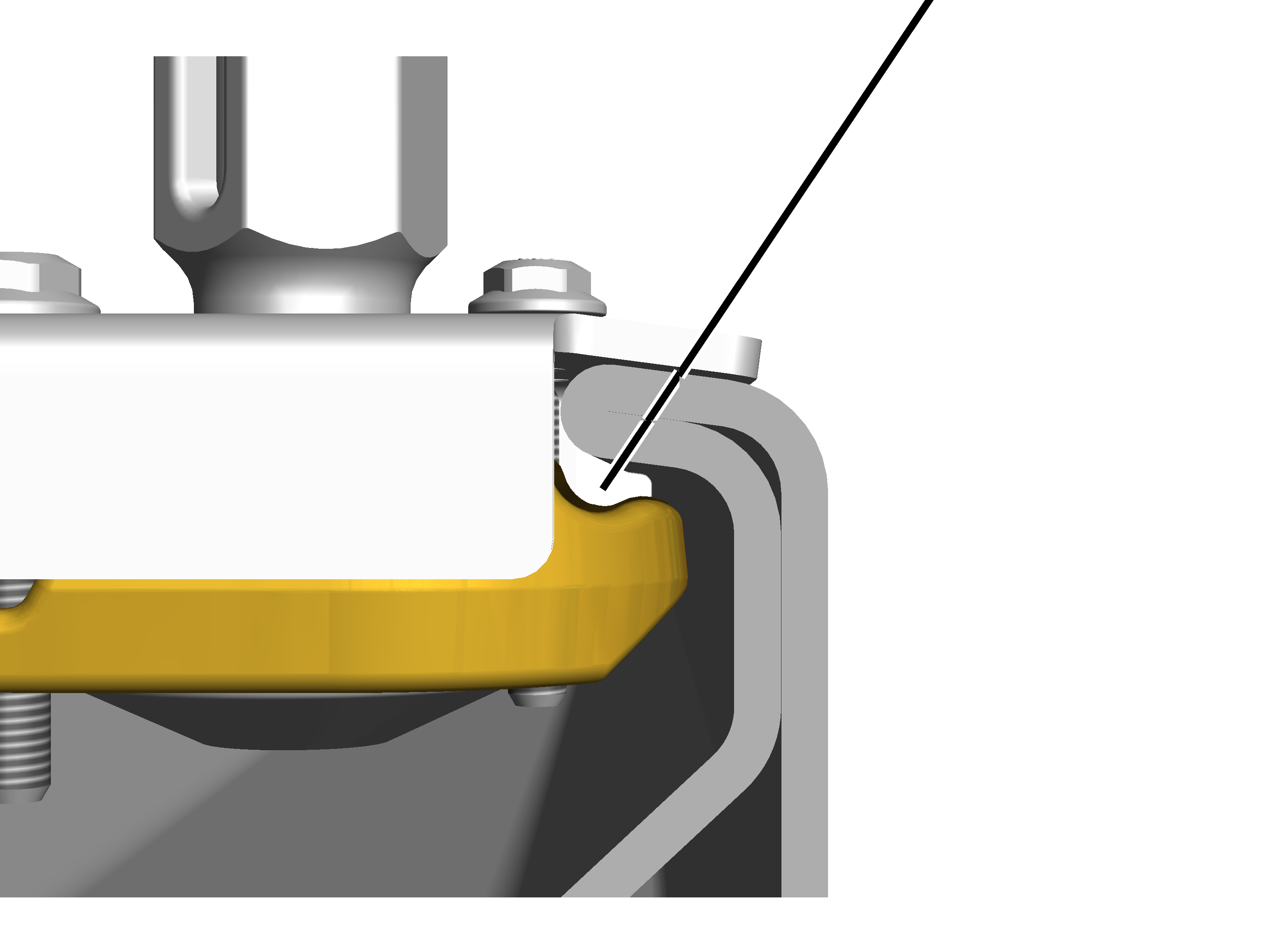
- The profile link and the profile head must have direct contact.
- Between the profile link and the profile head no gap should be visible.
Adjusting the craneway suspension
To adjust the slant of the threaded rods:
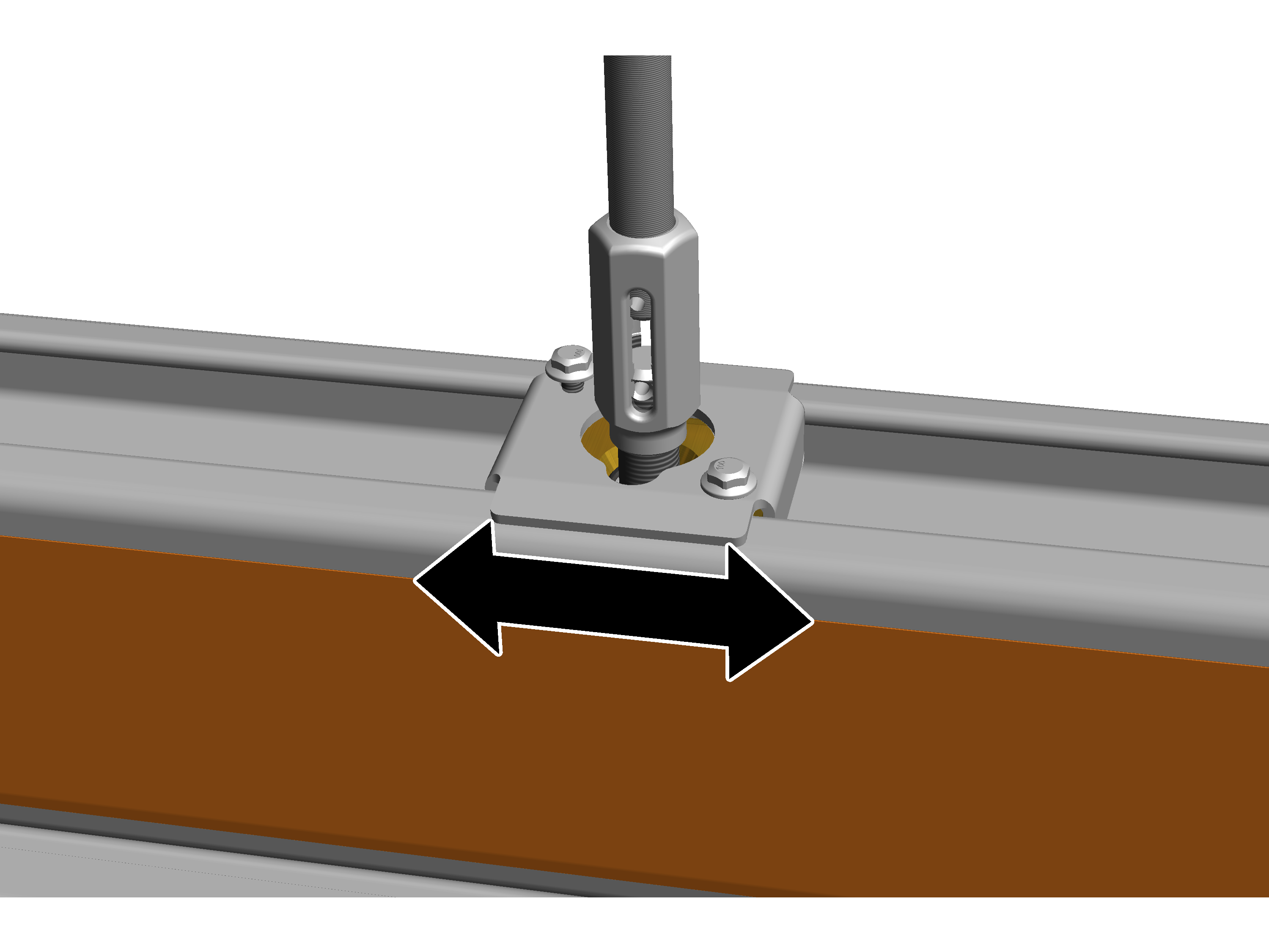
- Position the profile connection in the profile head to adjust the slant of the threaded rods.
To set the contact surface between profile link and profile head:
- Turn the tension nut to bring the profile link and profile head into direct contact.
Bolting on and securing the crane track to the craneway suspension
Securing the craneway suspension
On all craneway suspensions:
Threaded rodTension nut
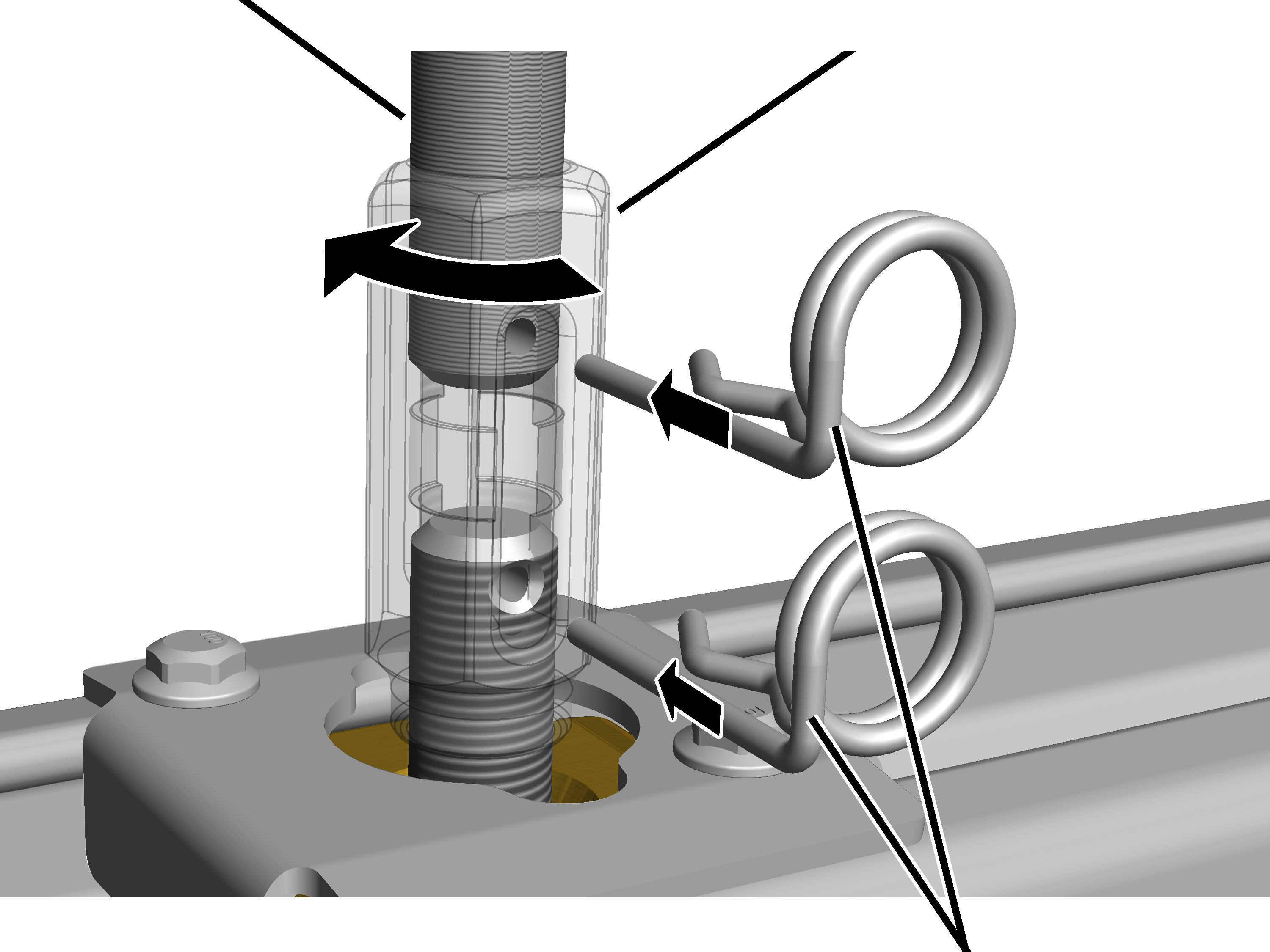
- Turn the tension nut and the threaded rod so far that the rectangular hole of the tension nut and the bore in the threaded rod are facing the same way (aligned with the HB crane runway).
If the two holes are not to be visible at the same time, the wrong hole of the cross-drilled hole on the ceiling-mounted bracket 2LP/M16 or M20 may have been used (see "Craneway suspension M16: installing a normal suspension"), or the hole in the threaded rod was not drilled in alignment with the existing hole after shortening (see "Shortening or lengthening threaded rods").
If necessary, e.g. to compensate for inaccuracies, the hole in the threaded rod can be enlarged to a diameter of 5 mm.
- Insert the spring cotter at the bottom through the tension nut into the hole of the profile connection.
- Insert the spring cotter at the top through the tension nut into hole in the threaded rod.
Final tightening of the ceiling-mounted bracket 2LP/M16 or M20
On all ceiling-mounted brackets 2LP/M16 or M20:
Rib screws (2x) or rib nuts (2x)
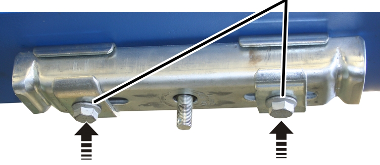
- Tighten the rib screws (2x) or rib nuts (2x) on the ceiling-mounted bracket 2LP/M16 or M20.
Suspension |
Tightening torque |
|---|---|
Flange clamp |
200 Nm |
Weld-on block |
200 Nm |
Anchor rod |
200 Nm |
Anchor connection |
90 Nm |
Anchor bar |
200 Nm |
Wooden beams |
90 Nm |
Rib nut |
e.g. 200 Nm (*) |
Rib screw |
e.g. 200 Nm (*) |
Example: 200 Nm for M16, bolt quality grade 8.8 and friction coefficient 0.12.
Final tightening of the profile connections
On all profile connections:
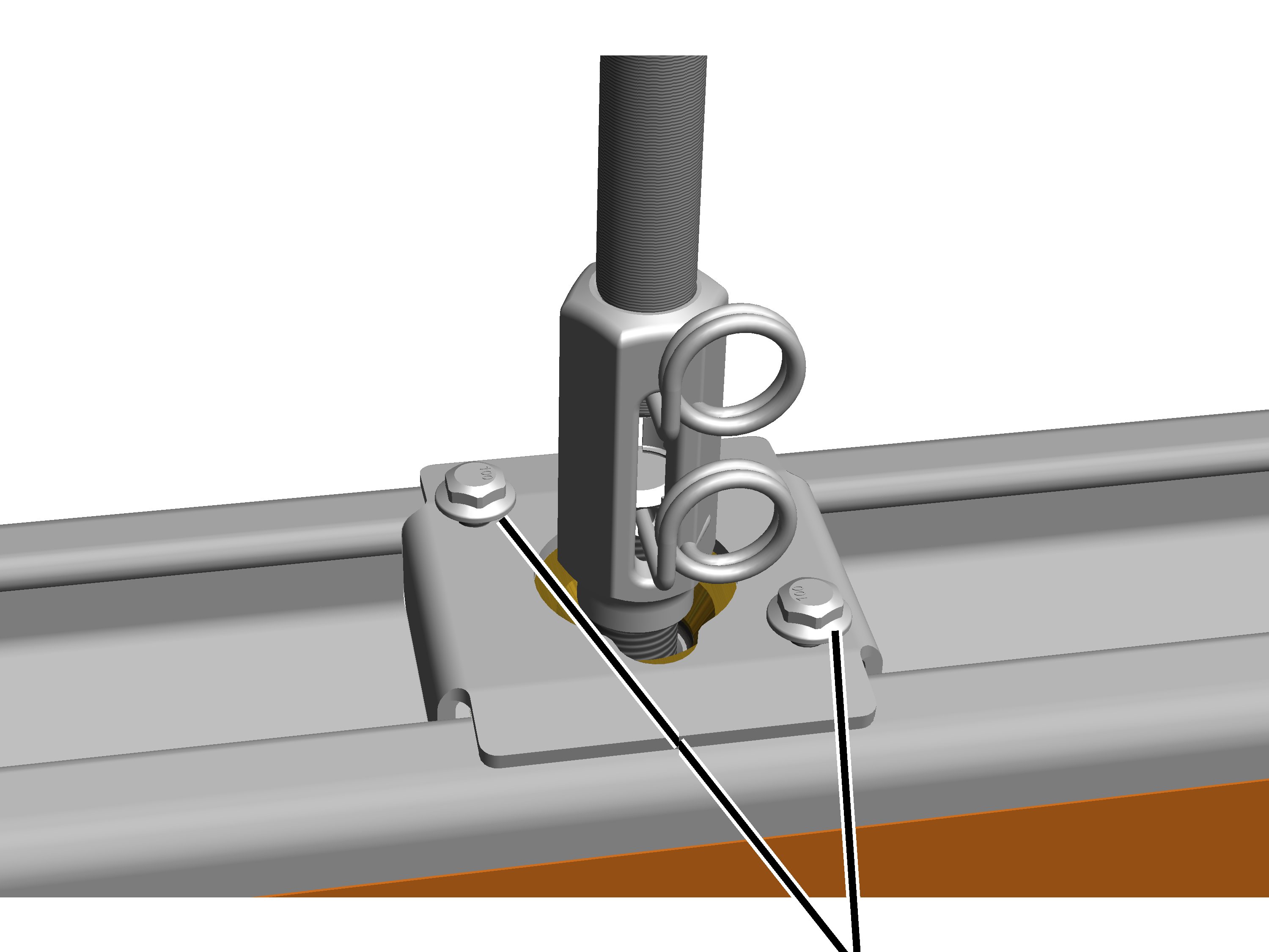
- Tighten the rib screws (2x) on the profile connection.
Size |
Rib screw |
Tightening torque |
|---|---|---|
HB110 |
M5x30 |
11 Nm |
HB150 |
M6x40 |
20 Nm |
HB190 |
M6x40 |
20 Nm |
HB240 |
M6x40 |
20 Nm |
Tip:
For the profile connections on the HB110, M5x30 fillister-head screws are used. The screws lie quite close to the tension nuts. To screw them easily, use a bit with a spherical head.
Only with normal stiffener, inclined stiffener and V-suspension
Final tightening of the articulated girder
Hexagonal nuts
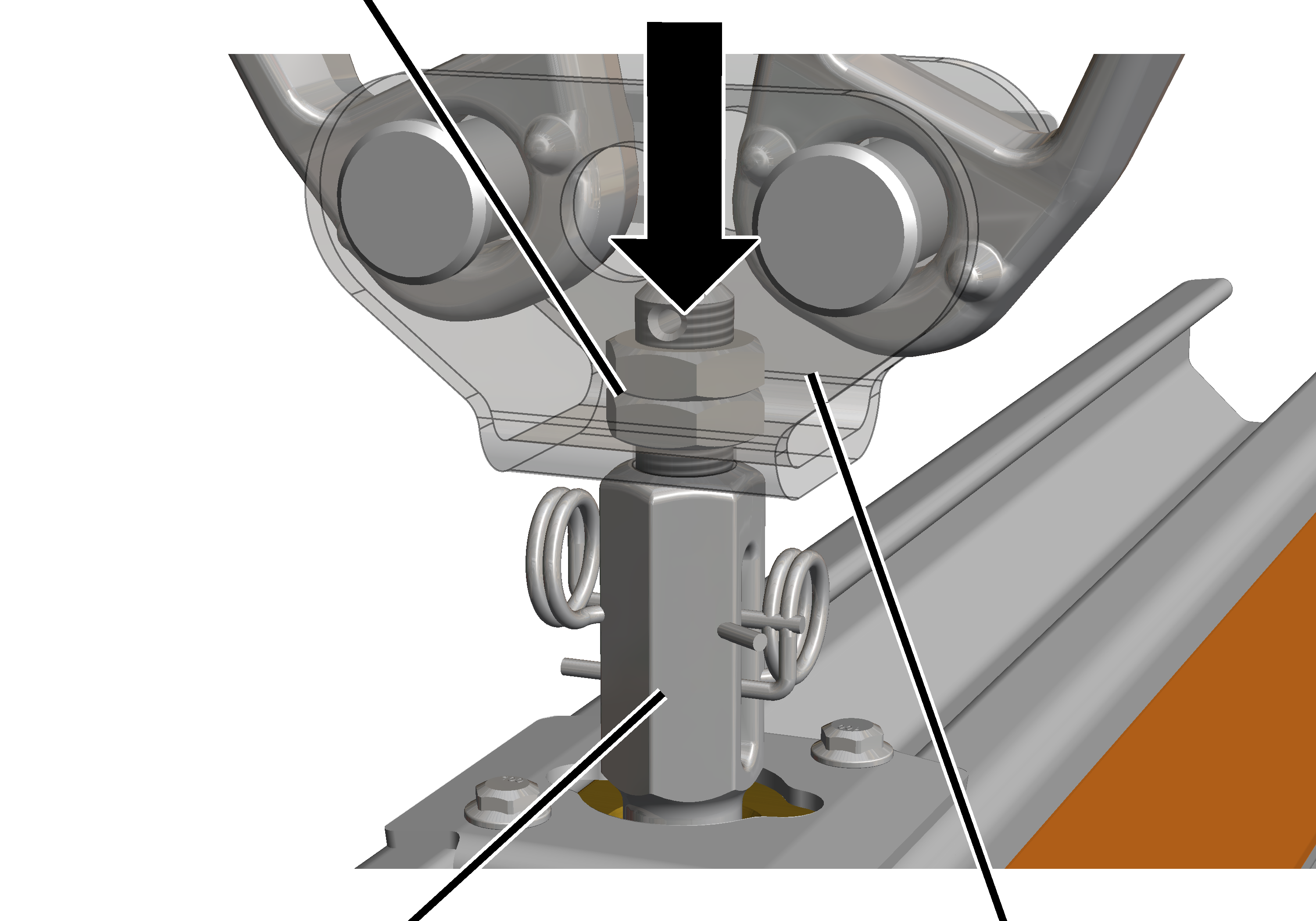
- Press the articulated girder against the tension nut.
- Screw on hexagonal nut. Tighten to 90 Nm.
- Lock with a second hexagonal nut.
Installing the terminal box
Only with festoon cable system and conductor system VKL
Rib screw M8x25
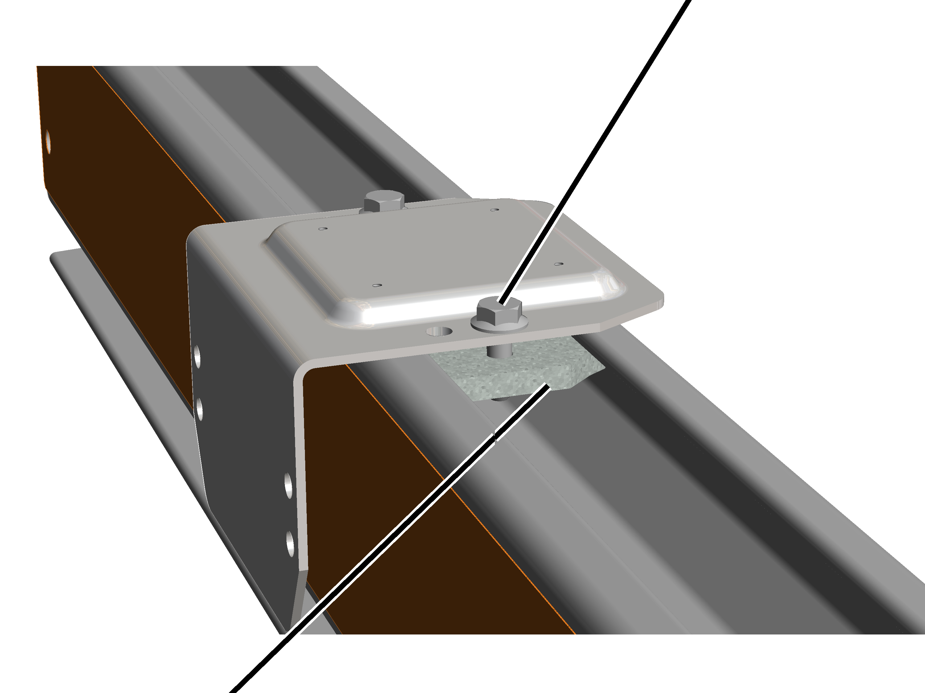
- If required: insert rib screw M8x25 (2x) in base plate and screw the head nut (2x) onto the rib screw from below.
- Turn the head nut in the longitudinal direction and lay the base plate on the profile head from above.
- The head nut extends into the profile head.
- Tighten the rib screws to 25 Nm.
- The head nut turns during fixing in the crosswise direction and is clamped tight in the profile head.
Fillister-head screw M4x10
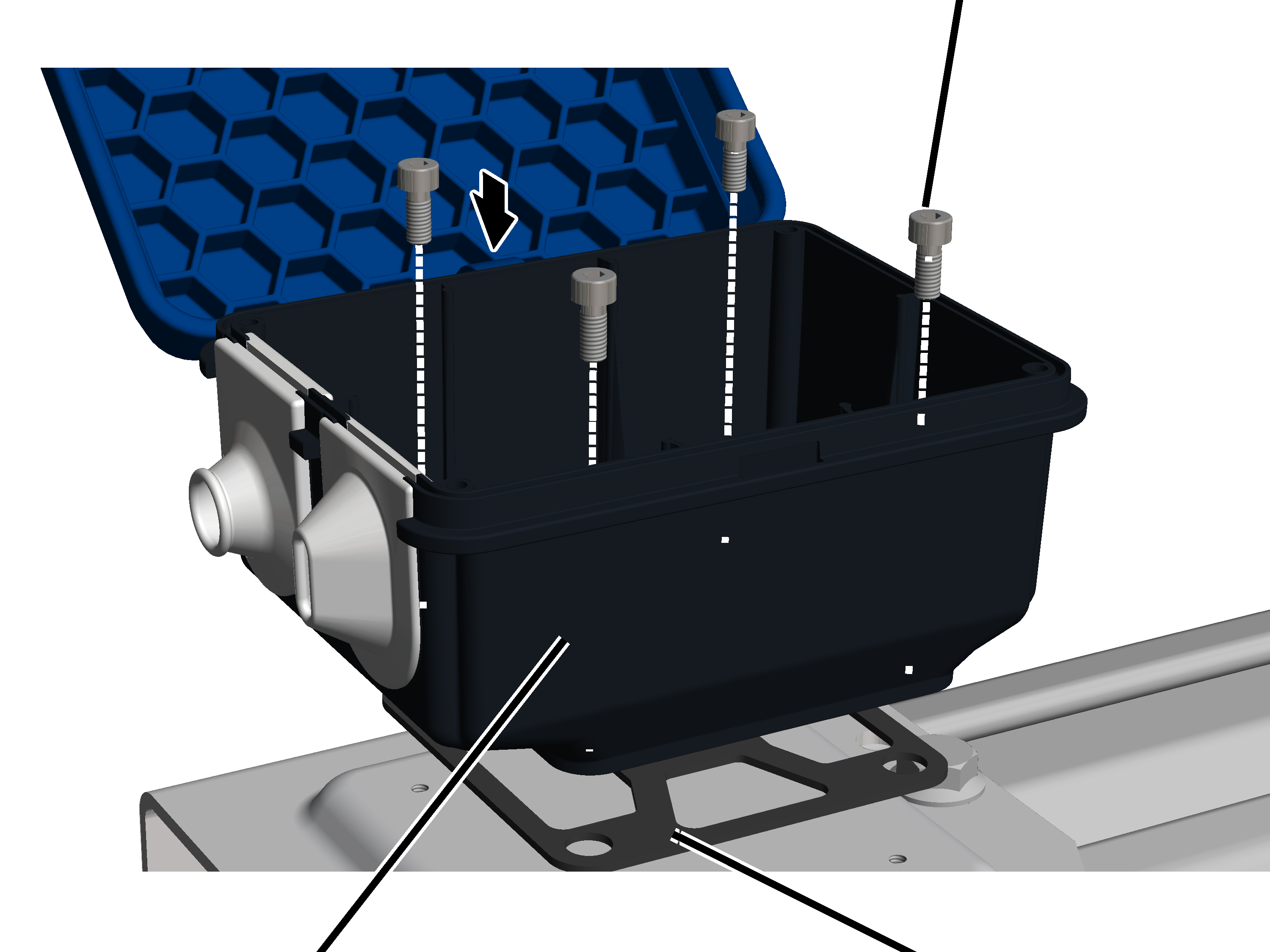
- Stick the self-adhering seal under the connector housing.
- Bolt the connector housing onto the base plate with fillister-head screws M4x10 (4x).
Inserting the trolleys
Inserting the trolleys
Only with trolley HB5 and HB6
Trolley
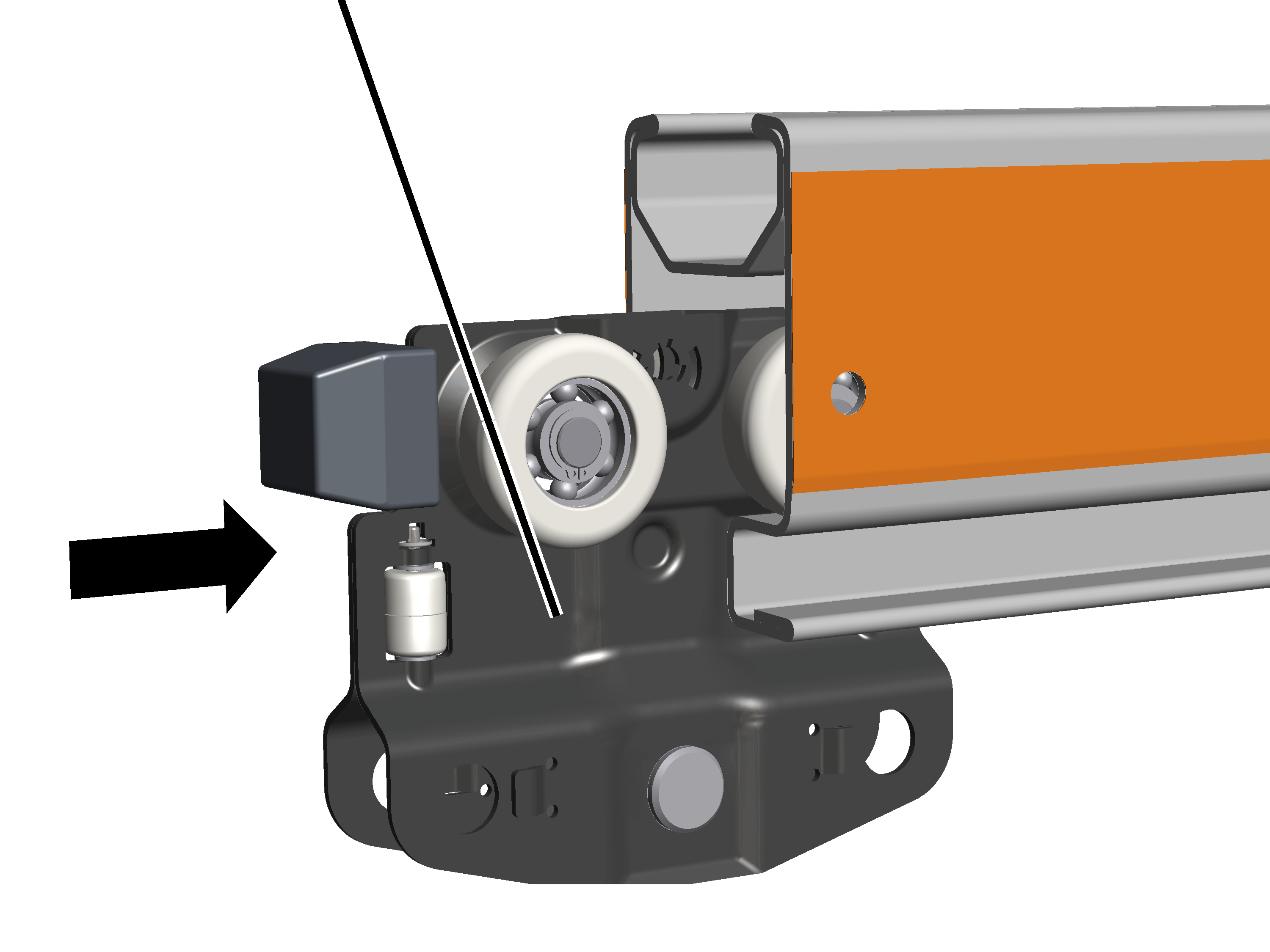
- Slide a trolley HB5 / HB6 into the HB profile rail.
- With trolley HB10 / HB11: slide two trolleys (prefitted with cross bar HB10/HB11 if appropriate) into the HB profile rail.
- With trolley HB22: slide four trolleys (prefitted with cross bar HB22 if appropriate) into the HB profile rail.
Only with trolley HB10 and HB11
Fitting HB10/HB11
A cross bar HB10/HB11 is now fitted to the trolleys.
Trolleys
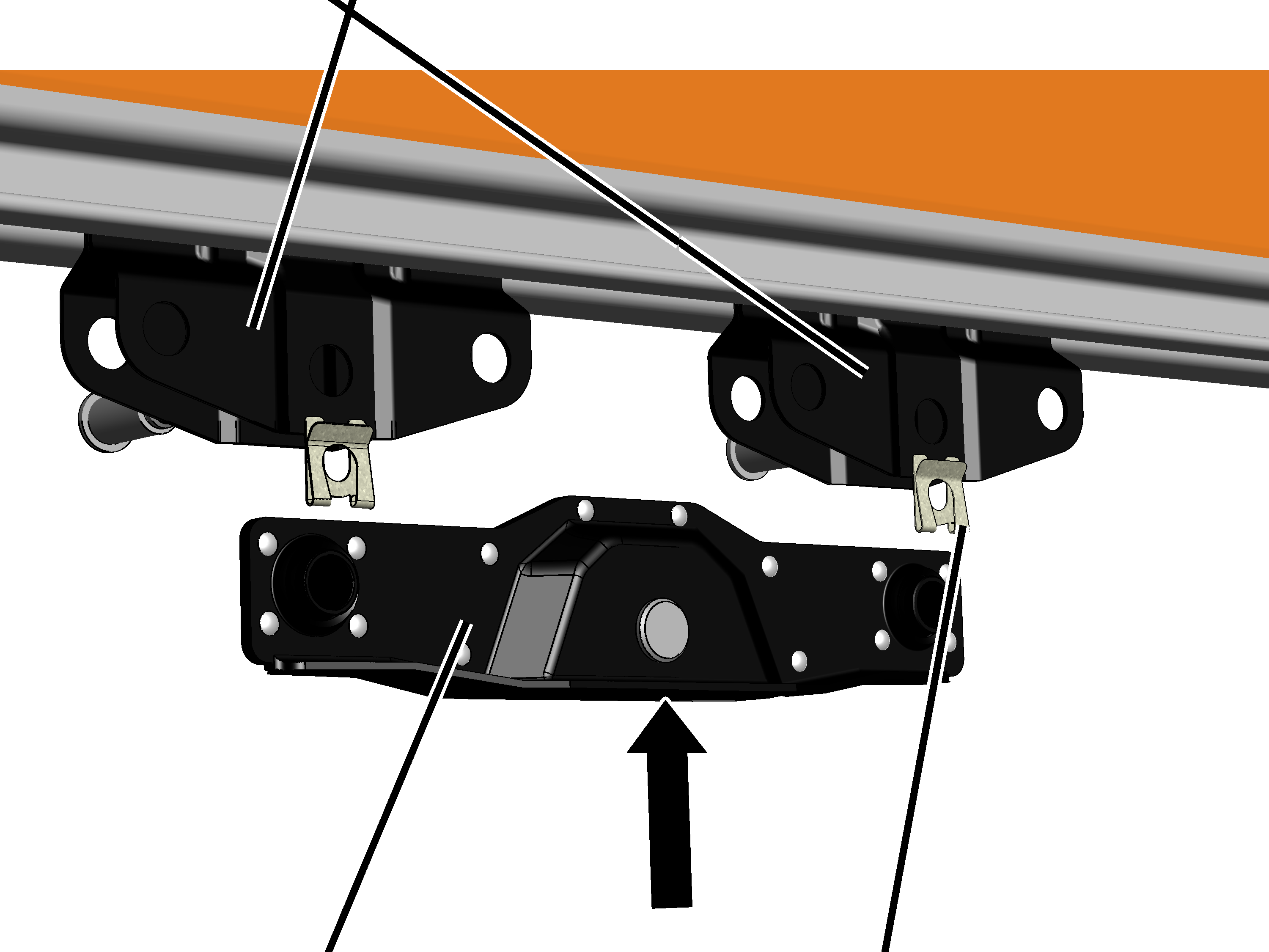
- Push the cross bar HB10/HB11 into the two trolleys HB6 from below.
- Push the bolts (2x) through the trolleys HB6 and cross bar HB10/HB11.
- Secure the bolts with the SL safety clips (2x).
Only with trolley HB22
Fitting cross bar HB22
One cross bar HB10/HB11 each is now fitted to the trolleys. Then one cross bar HB22 is fitted to these.
Trolley
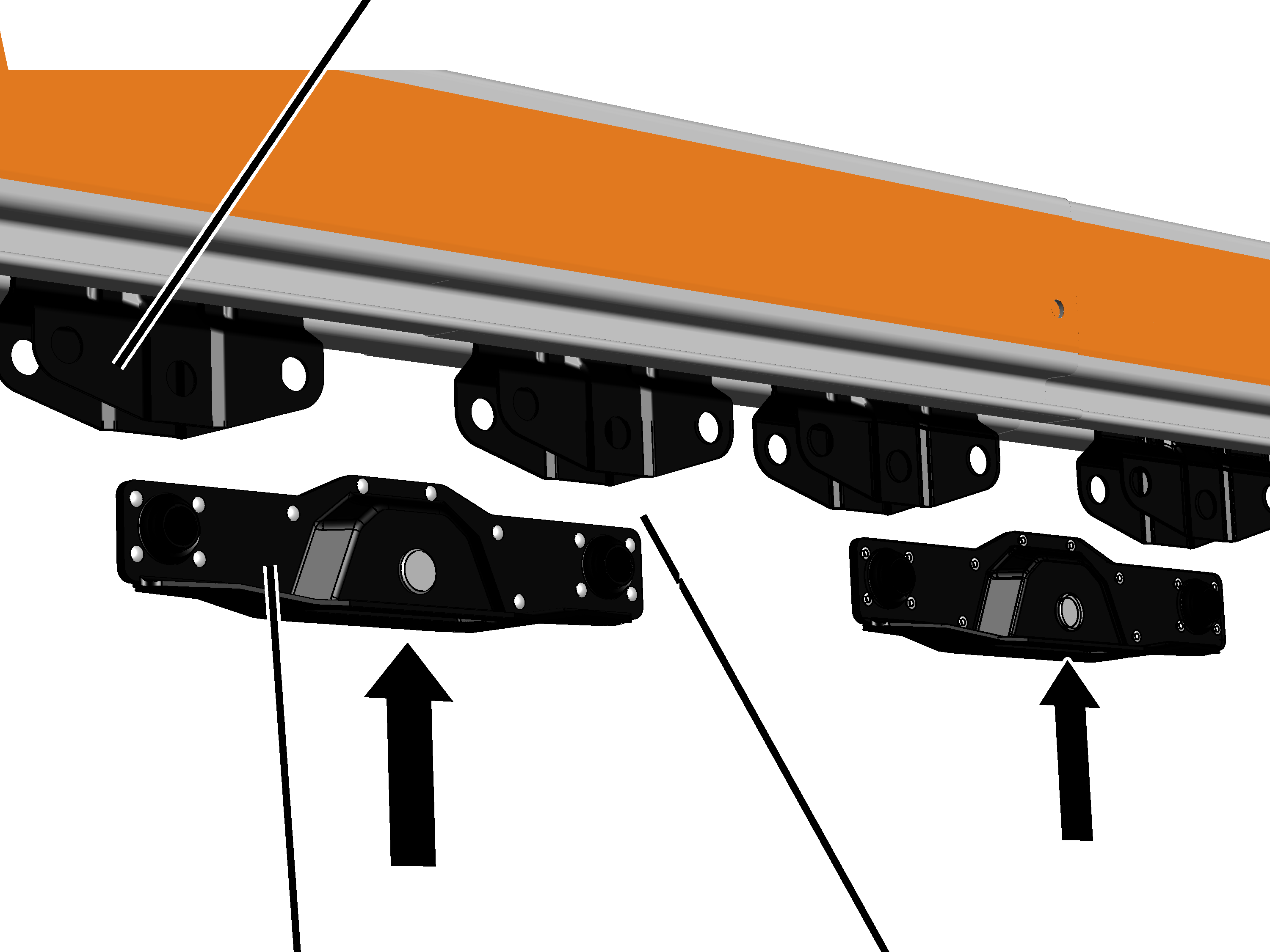
- Push the cross bar HB10/HB11 (2x) into the trolleys HB6 from below.
- Push the bolts (4x) through the trolleys HB6 and cross bar HB10/HB11.
- Secure the bolts with the SL safety clips (4x).
Cross bar HB10/HB11
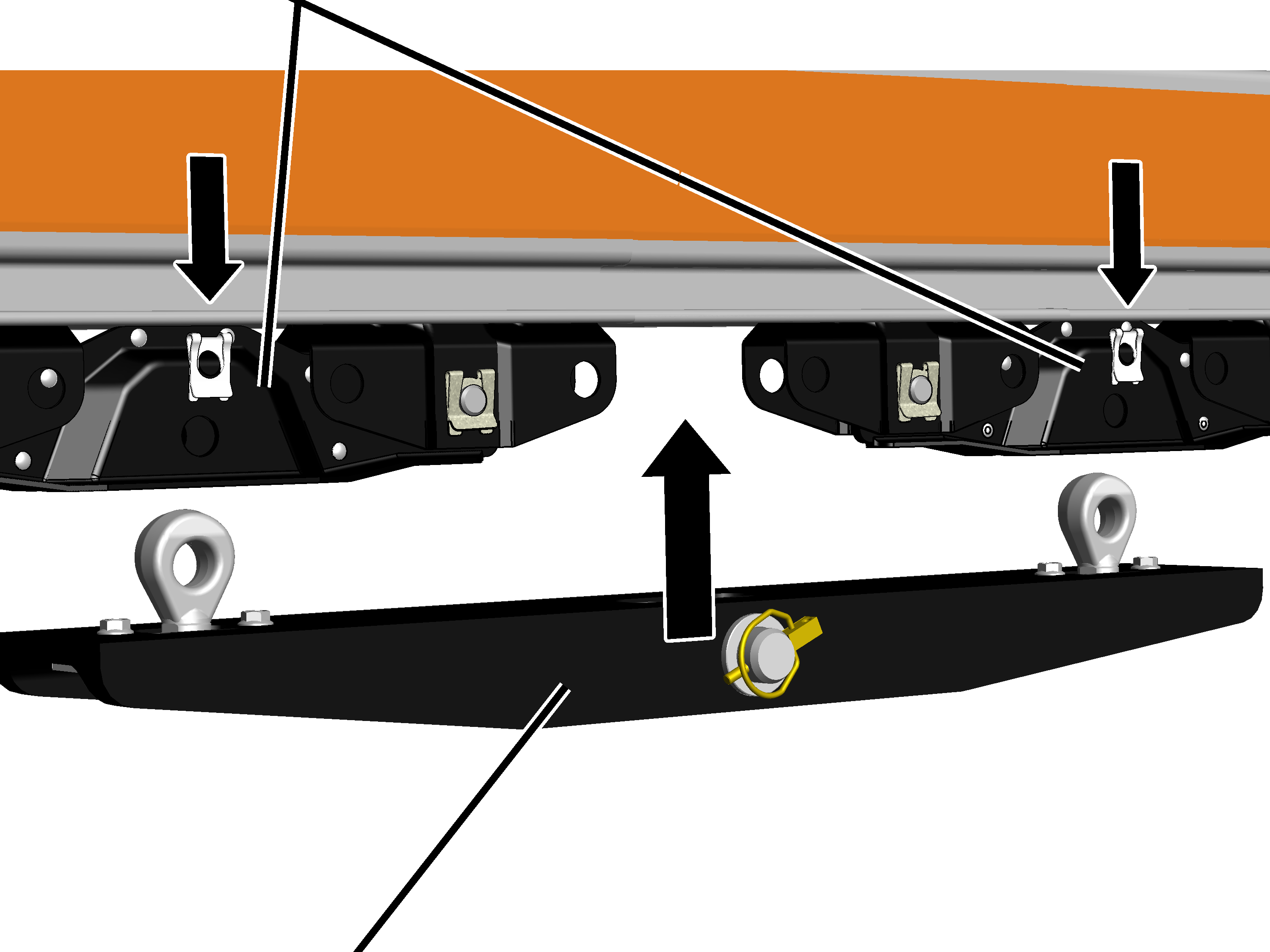
- Push cross bar HB22 into the cross bar HB10/HB11 from below.
- Push the bolts (2x) through the cross bar HB10/HB11 and the eyebolts of the cross bar HB22.
- Secure bolt with SL safety clip.
Further installation of an HB crane or trolley is described in the corresponding product manual.
Installing the HBF drive
The HBF drive consists of a travel motor with friction wheel, which runs underneath the HB profile rail, and an HBF trolley, which runs in the HB profile rail and is connected with the HBF drive. The unit comprised of HBF drive and HBF trolley is connected by means of a coupling bar to the HB crane or to the trolley.
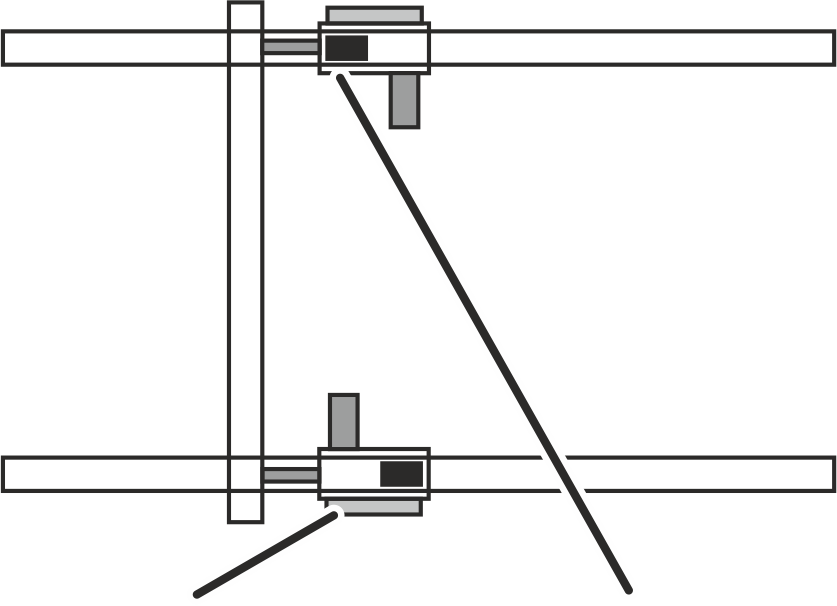
The HBF drives are installed in such a way that the travel motor is always facing inwards so that the motor does not project on the outside. For this reason, one of the HBF drives is connected to the crane or trolley on the friction wheel side and the other HBF drive is connected to the crane or trolley on the travel motor side.
Only for connection of the HBF drive on the friction wheel side
This section only applies if the HBF drive is to be connected to the crane or trolley on the friction wheel side.
Pre-assembling the HBF drive
On every HBF drive:
Fork partHBF trolley
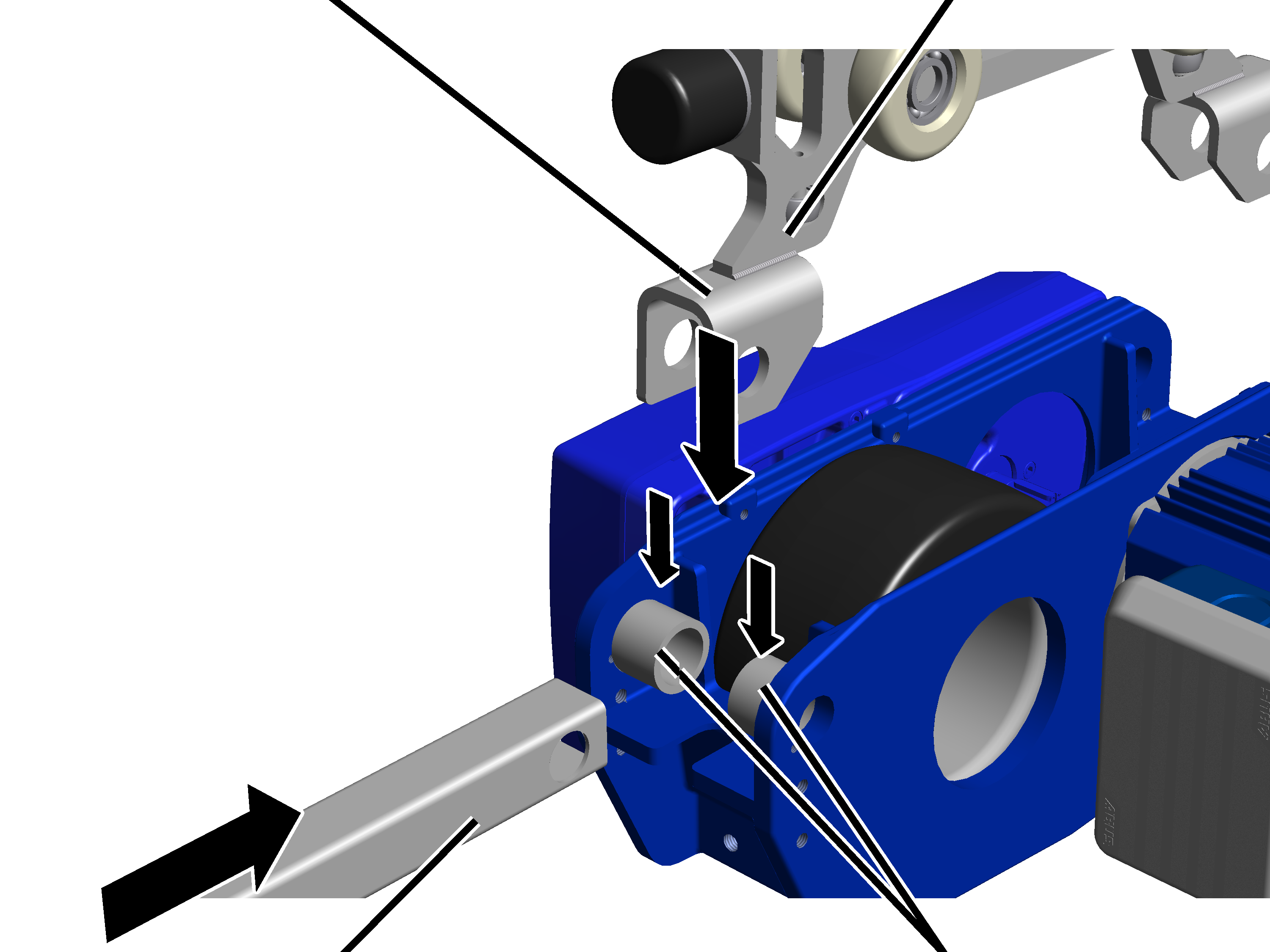
- Move the bushes (2x) left and right and the fork part to the centre between the HBF drive on the friction wheel side.
- Push the coupling bar between the fork part from the front.
Bolt
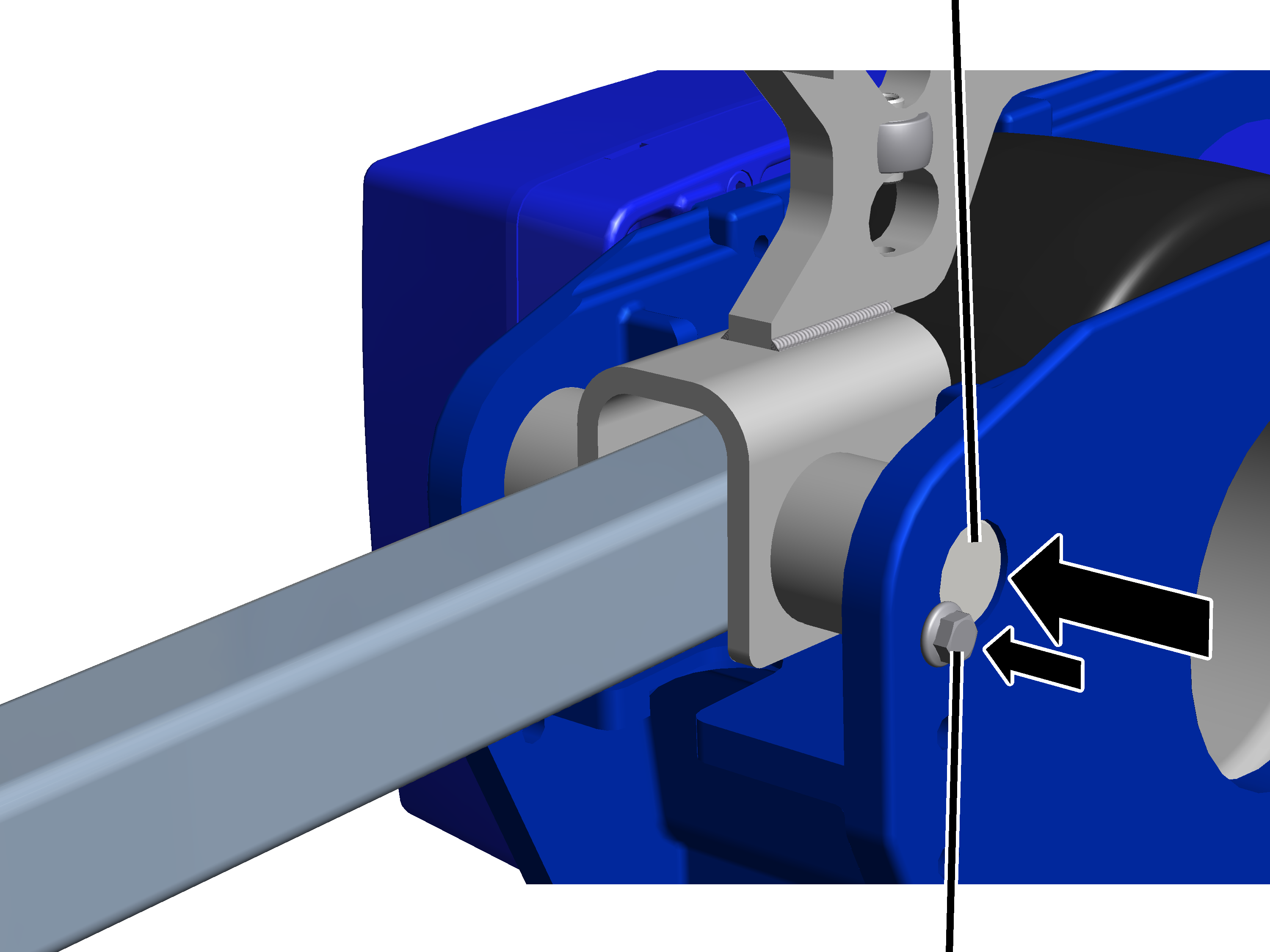
- Push the bolt laterally through the HBF drive, the bushes, the fork part and the coupling bar.
- Screw the rib screw M5x10 (2x) in next to the bolt. 11 Nm.
- The bolt is fixed in place from both sides by the rib screw.
EyeboltCoupling (only with anti-collision device as preceding trolley)
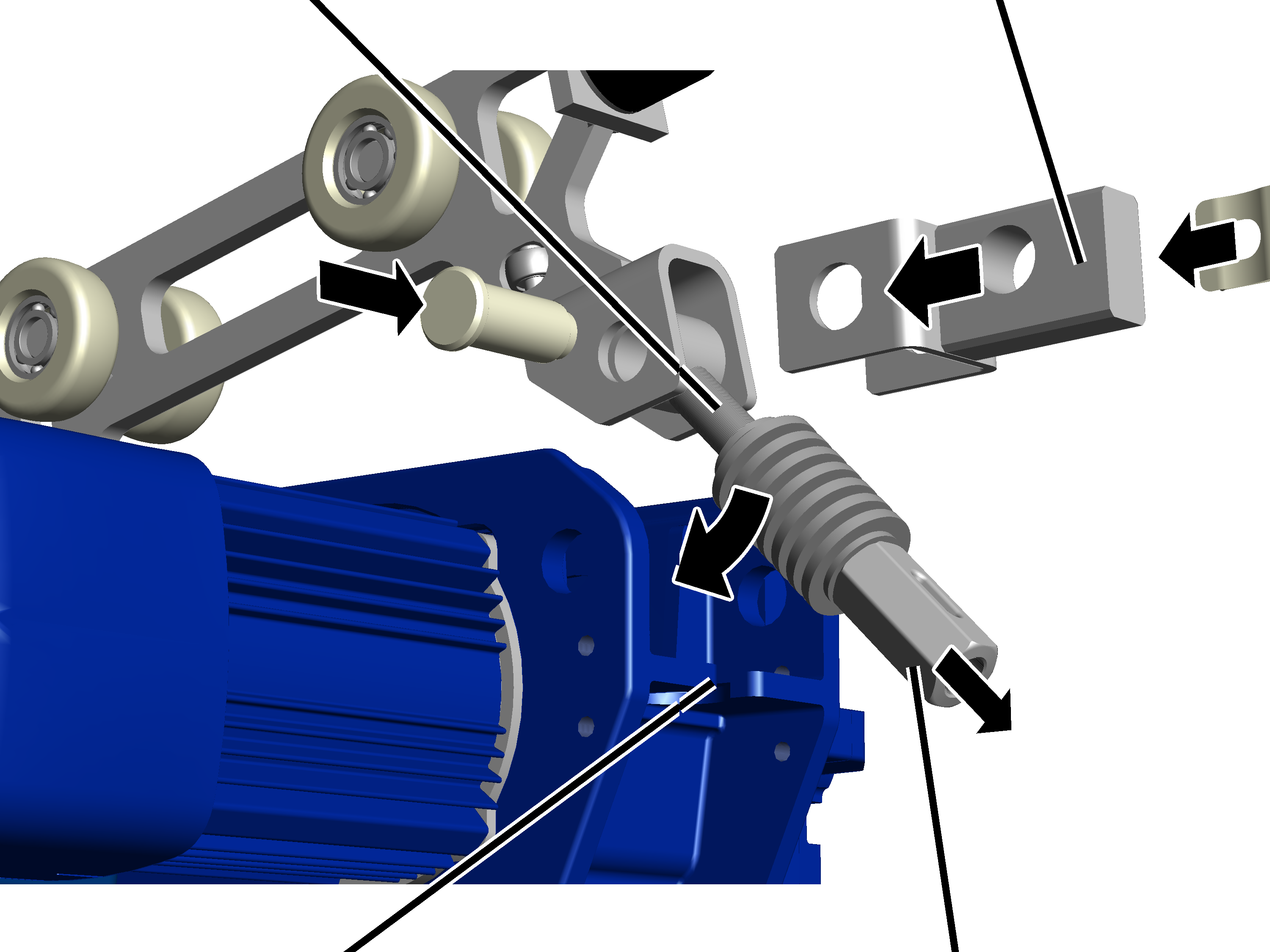
- On the other side on the HBF drive, insert the eyebolt inside the fork part.
- Only with anti-collision device as preceding trolley or with coupling bar: if, on the HBF drive side, an anti-collision device as preceding trolley or an anti-collision device with coupling bar is to be installed, push a coupling over the fork part.
- Push the bolt through the fork part and eyebolt (and coupling if appropriate).
- Secure bolt with SL safety clip.
- Unscrew the coupling from the eyebolt until it is only a few turns from the end.
- This allows the eyebolt to be suspended without counter-pressure from the plate springs.
- Hook the eyebolt in the recess on the HBF drive. The plate spring pack then goes under the recess on the HBF drive.
Inserting and fastening the HBF drive
Crane/trolley travel mechanismHBF trolley
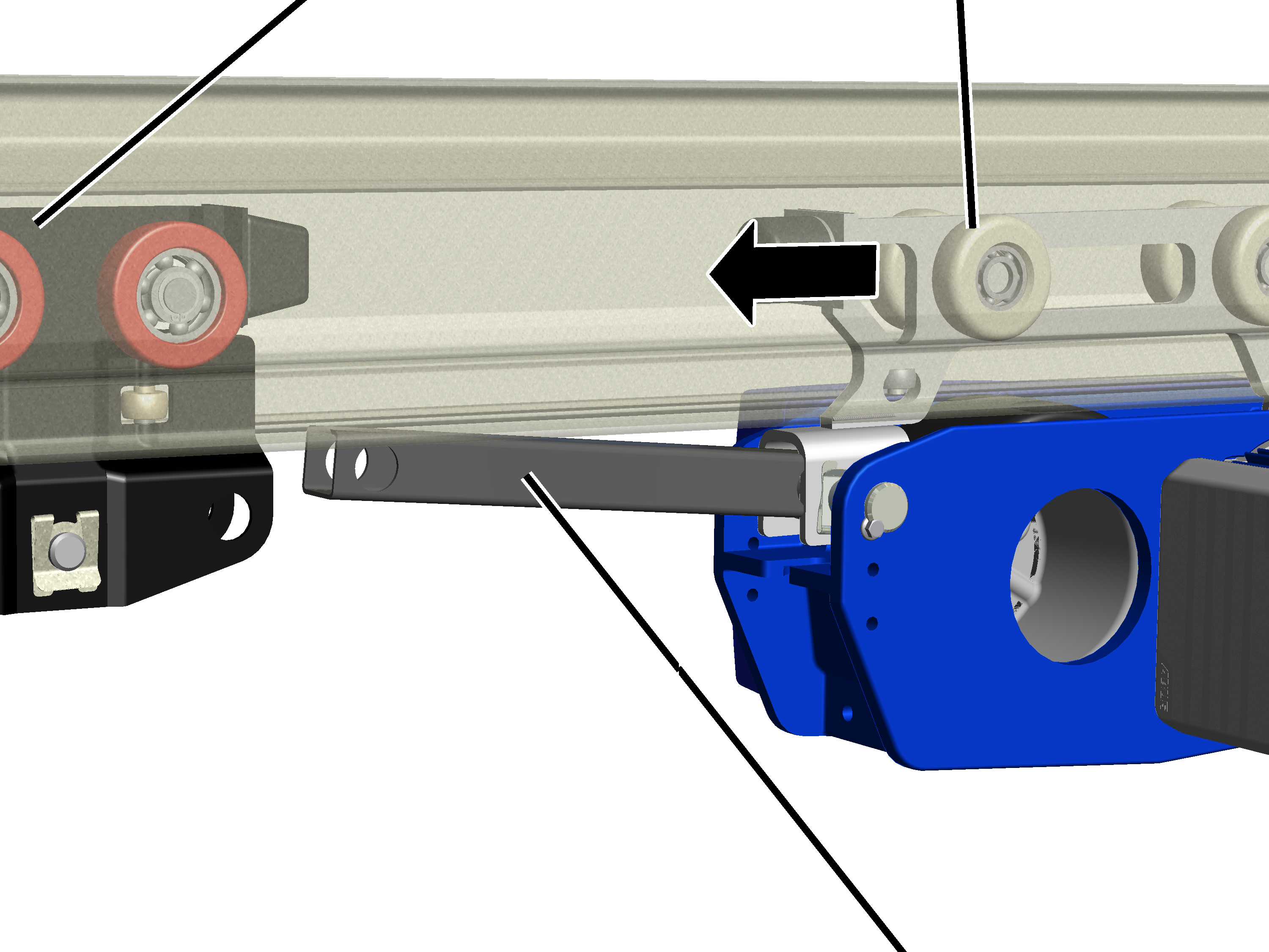
- Turn the HBF drive so that the coupling bar points toward the trolley on which the HBF drive is to be fixed.
- Push the HBF drive with HBF trolley into the HB profile rail.
Bolt
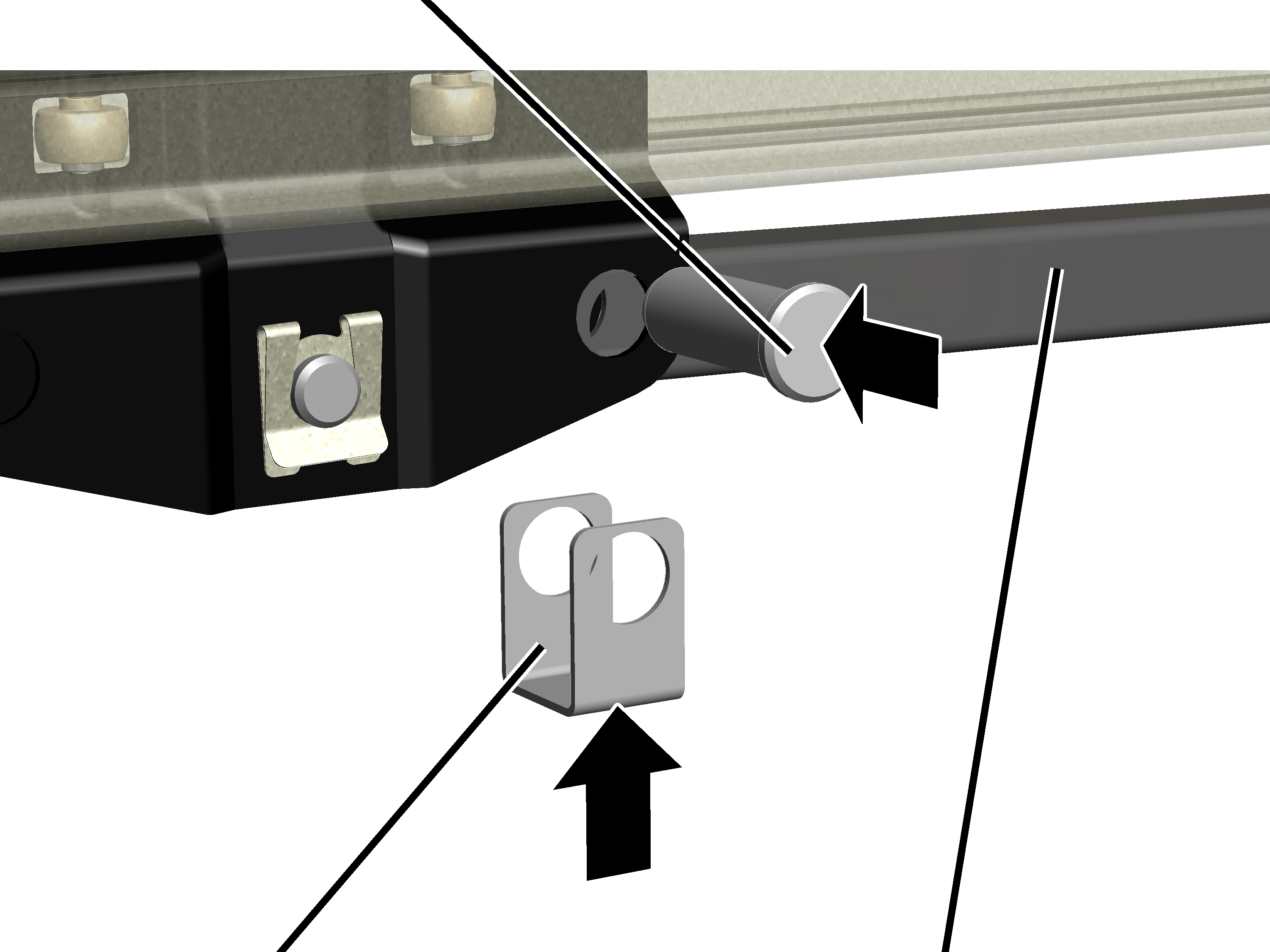
- Push the HBF drive with the coupling bar up to the trolley.
The coupling bar is fixed in the hole facing the HBF drive.
- Insert a spacer bracket between trolley and coupling bar.
- Insert bolt through trolley and coupling bar.
- Secure bolt with SL safety clip.
Tensioning the plate springs
The plate springs serve in setting the pressure with which the friction wheel presses the HBF drive against the HB profile rail.
Plate springs
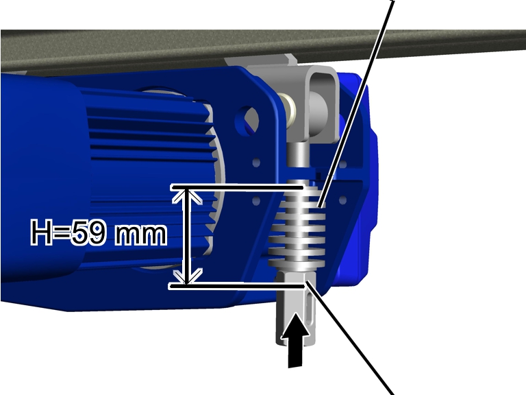
- Turn the coupling until the plate springs (including the upper and lower discs) are H = 59 mm in length.
- Secure coupling with spring cotter.
- The friction wheel now presses hard enough against the HB profile rail.
Only for connection of the HBF drive on the travel motor side
This section only applies if the HBF drive is to be connected to the crane or trolley on the travel motor side.
Pre-assembling the HBF drive
On every HBF drive:
Fork partHBF trolley
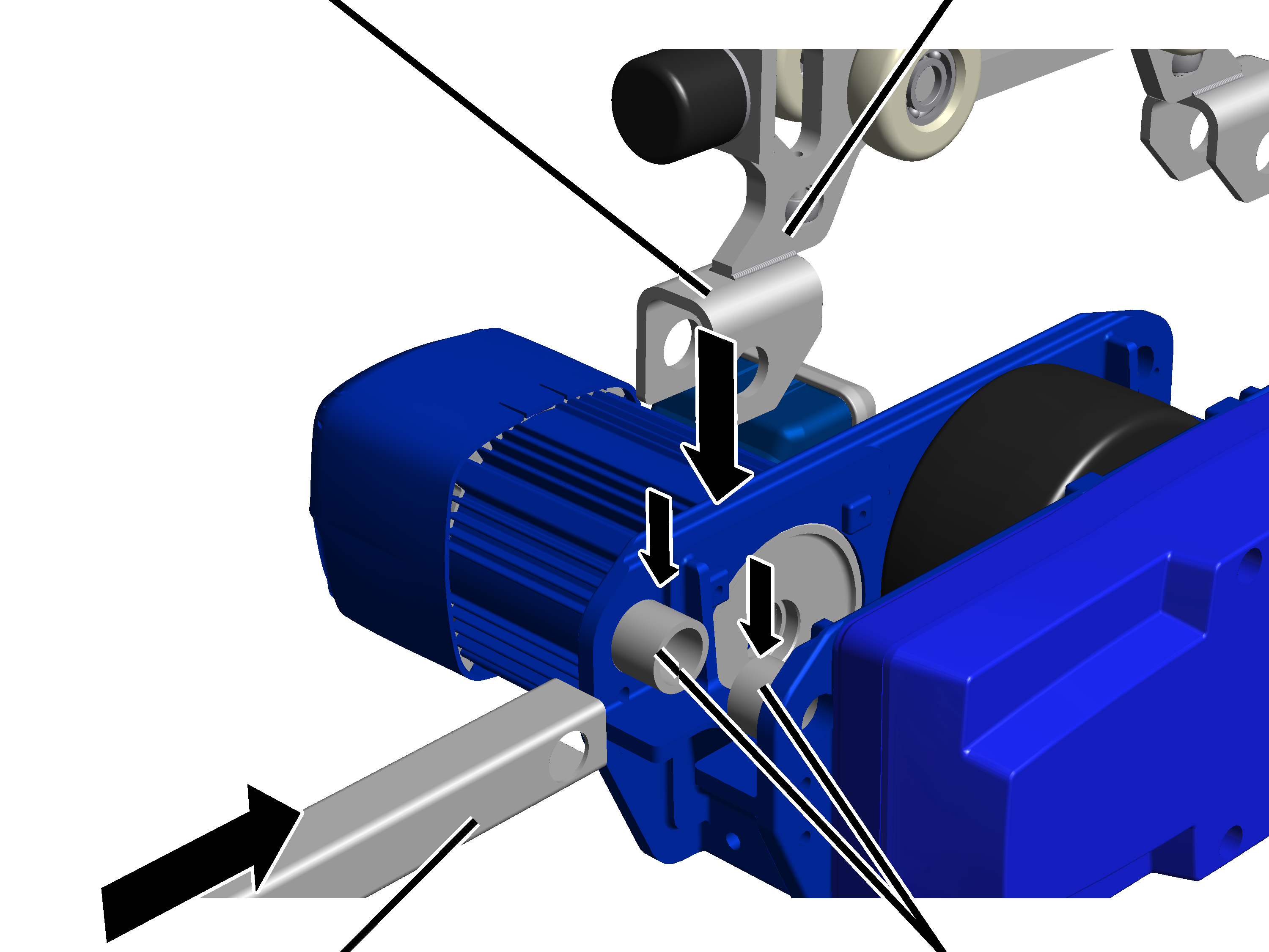
- Bring the left and right bushes (2x) as well as the fork part to the centre between the HBF drive on the travel motor side.
- Push the coupling bar between the fork part from the front.
Rib screws M5x10
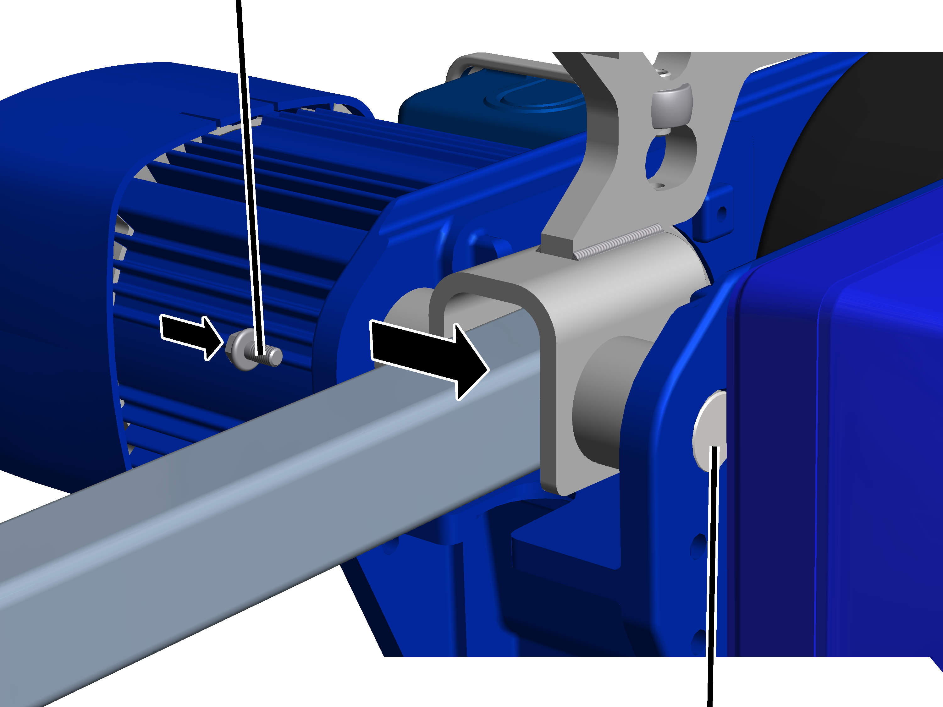
- Push the bolt laterally through the HBF drive, the bushes, the fork part and the coupling bar.
- Screw the rib screw M5x10 (1x) in next to the bolt. 11 Nm.
- The bolt is fixed in place on one side by the gear unit and on the other side by the rib screw.
EyeboltCoupling (only with anti-collision device as preceding trolley)
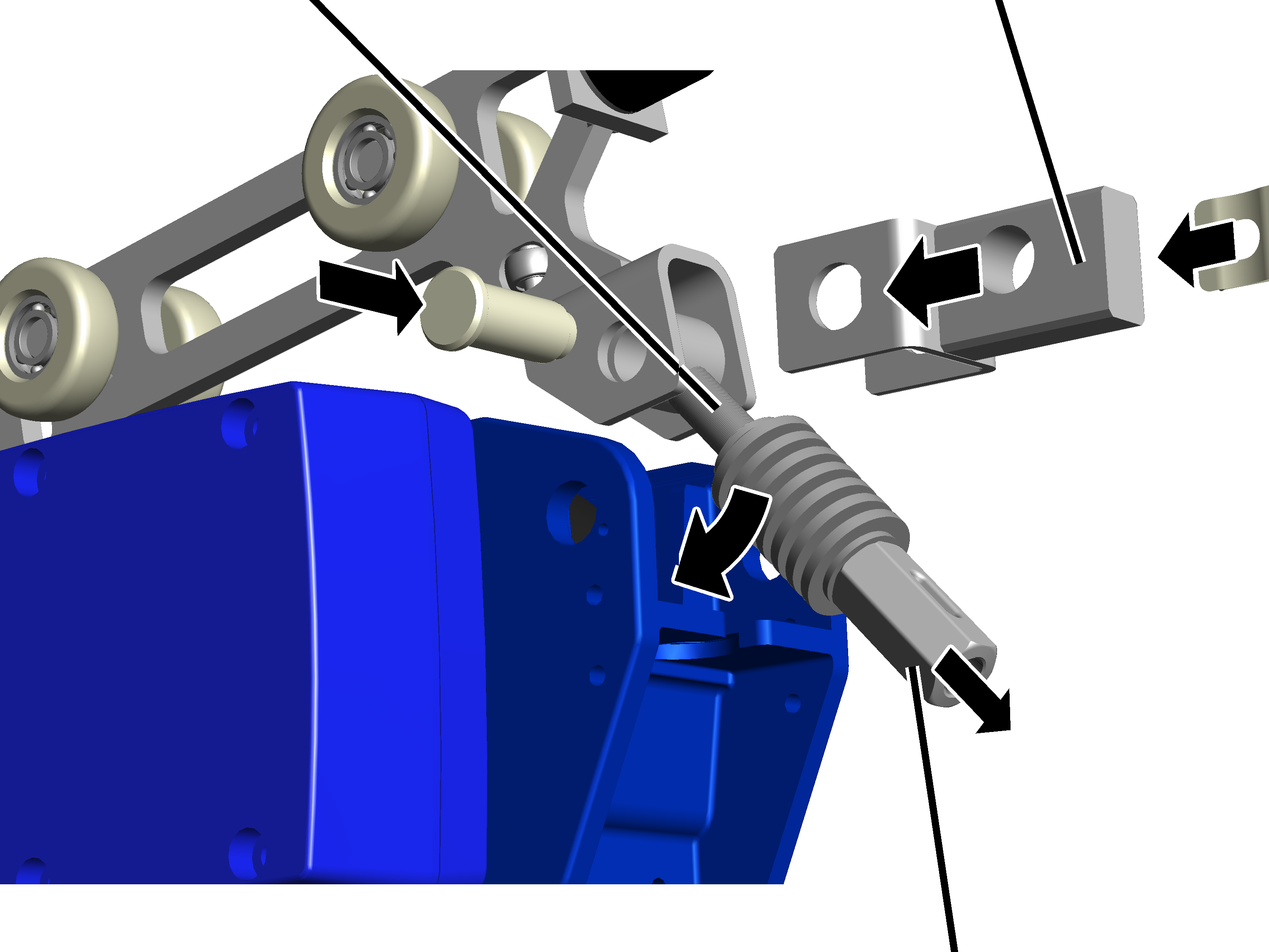
- On the other side on the HBF drive, insert the eyebolt inside the fork part.
- Only with anti-collision device as preceding trolley or with coupling bar: if, on the HBF drive side, an anti-collision device as preceding trolley or an anti-collision device with coupling bar is to be installed, push a coupling over the fork part.
- Push the bolt through the fork part and eyebolt (and coupling if appropriate).
- Secure bolt with SL safety clip.
- Unscrew the coupling from the eyebolt until it is only a few turns from the end.
- This allows the eyebolt to be suspended without counter-pressure from the plate springs.
- Hook the eyebolt in the recess on the HBF drive. The plate spring pack then goes under the recess on the HBF drive.
Inserting and fastening the HBF drive
Crane/trolley travel mechanismHBF trolley
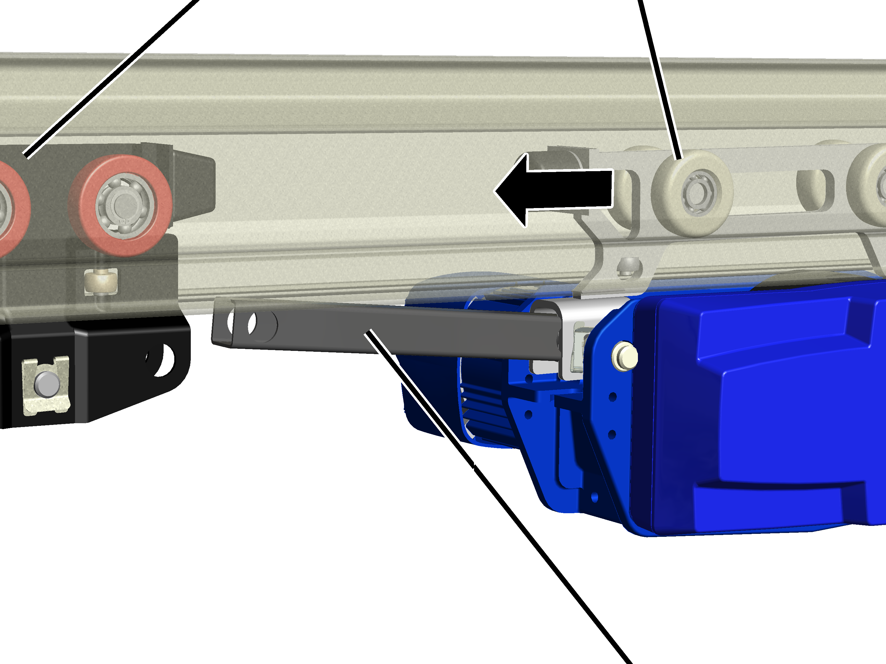
- Turn the HBF drive so that the coupling bar points toward the trolley on which the HBF drive is to be fixed.
- Push the HBF drive with HBF trolley into the HB profile rail.
Bolt
- Push the HBF drive with the coupling bar up to the trolley.
The coupling bar is fixed in the hole facing the HBF drive.
- Insert a spacer bracket between trolley and coupling bar.
- Insert bolt through trolley and coupling bar.
- Secure bolt with SL safety clip.
Tensioning the plate springs
The plate springs serve in setting the pressure with which the friction wheel presses the HBF drive against the HB profile rail.
Plate springs
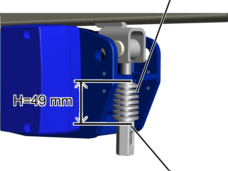
- Turn the coupling until the plate springs (including the upper and lower discs) are H = 49 mm in length.
- Secure coupling with spring cotter.
- The friction wheel now presses hard enough against the HB profile rail.
Only for HBF drive as crane travel drive
Checking the inclination
Once the crane can run with maximum load capacity:
- Suspend a load on the load hook which corresponds to the maximum load capacity of the crane.
- Run the crane a few metres.
- Measure the inclination of the crane (difference in position from one drive compared to the other drive).
If the inclination is greater than 2 degrees:
- Release or tighten the plate springs of the HBF drive.
- Measure the inclination again and correct it, if necessary.
An inclination of up to 2 is uncritical and occurs due to tolerances in the HBF drives and the friction wheels.
Installing the anti-collision device
The anti-collision device consists of trolleys on which a coupling bar is mounted.
Inserting the trolleys for the anti-collision device
In all HB profile rails and for each anti-collision device:
Trolley
- With an anti-collision device as preceding trolley: push an additional trolley into each HB profile rail.
- With a free-running anti-collision device: insert two additional trolleys in each HB profile rail.
- With an anti-collision device with coupling bar: no additional trolleys are necessary.
Only with anti-collision device as preceding trolley
Connecting trolleys
Preceding trolleyTravel mechanism of crane or trolley
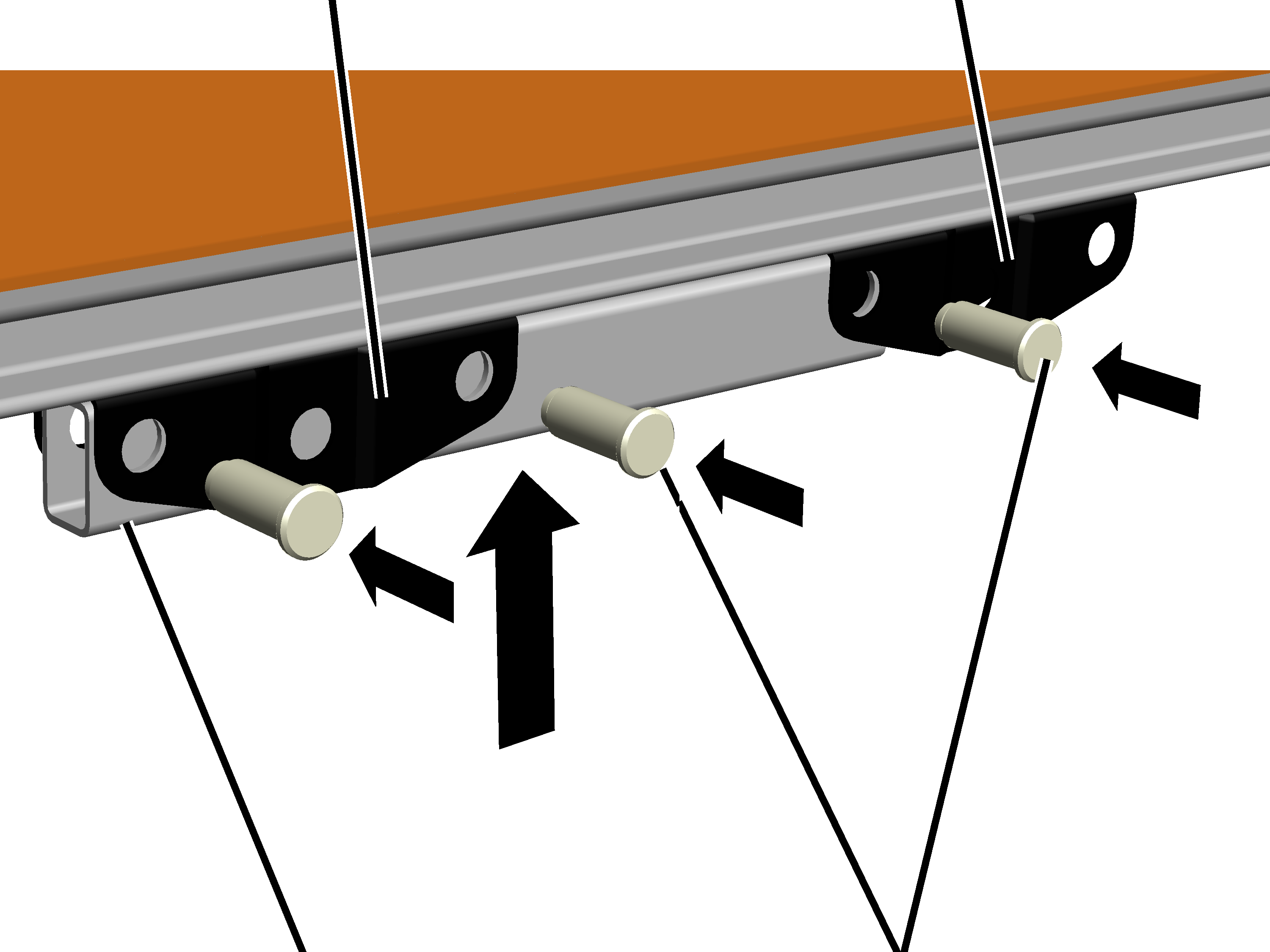
- On the preceding trolley: push the coupling bar inside the trolley.
- Push bolts (2x) through trolley and coupling bar.
- Secure bolts with SL safety clips (2x).
- On the travel mechanism of the crane or trolley: insert coupling bar through the front hole on the travel mechanism.
- Push bolt (1x) through the front hole on the trolley and through the coupling bar.
- Secure bolt with SL safety clips (1x).
Only with anti-collision device as preceding trolley (or with coupling bar) on the HBF drive
Connecting trolleys
CouplingBolt
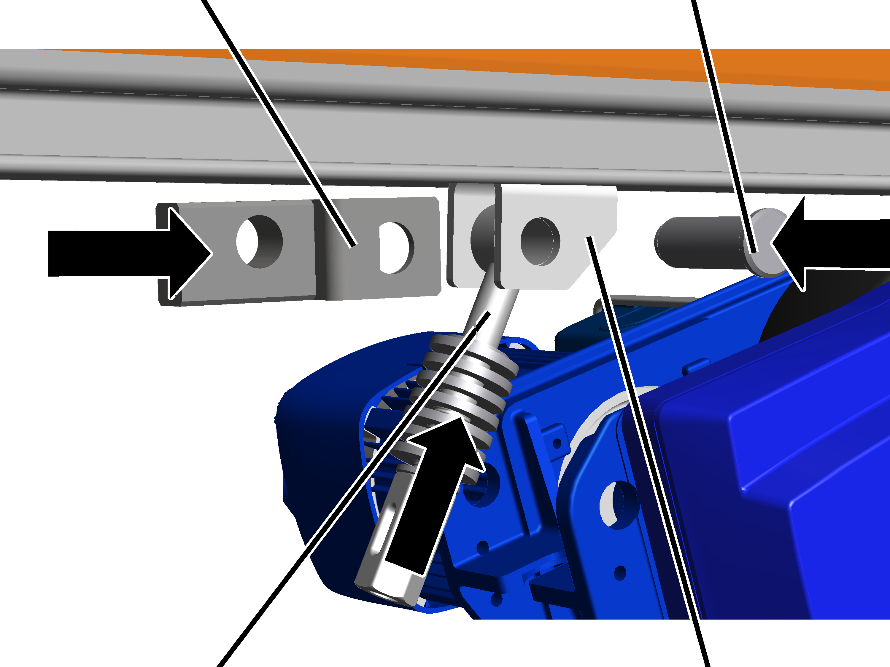
- If not yet already assembled: insert eyebolt between the fork part on the HBF drive, slide the coupling over the fork part, insert bolt and secure with the SL safety clip.
Connecting coupling bar with preceding trolley:
Preceding trolleyCoupling bar
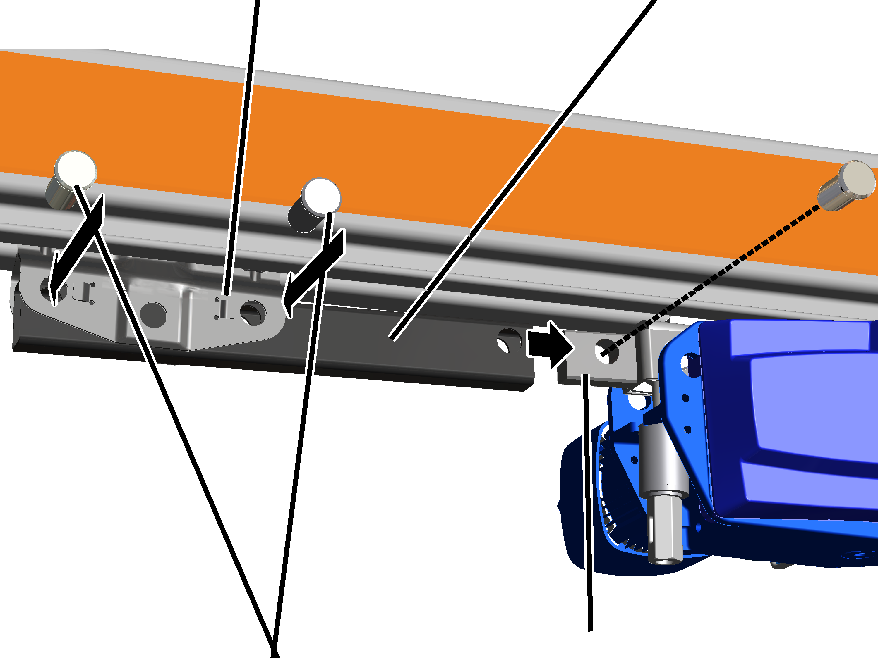
- On the preceding trolley: push the coupling bar inside the trolley.
- Push bolts (2x) through trolley and coupling bar.
- Secure bolt with SL safety clips (2x).
- On the HBF drive: push the coupling bar over the coupling.
- Push the bolt through the coupling bar and coupling.
- Secure bolt with SL safety clip.
Connecting coupling bar with other HB crane trolley or hoist trolley:
Hoist trolley (or crane trolley)Coupling bar
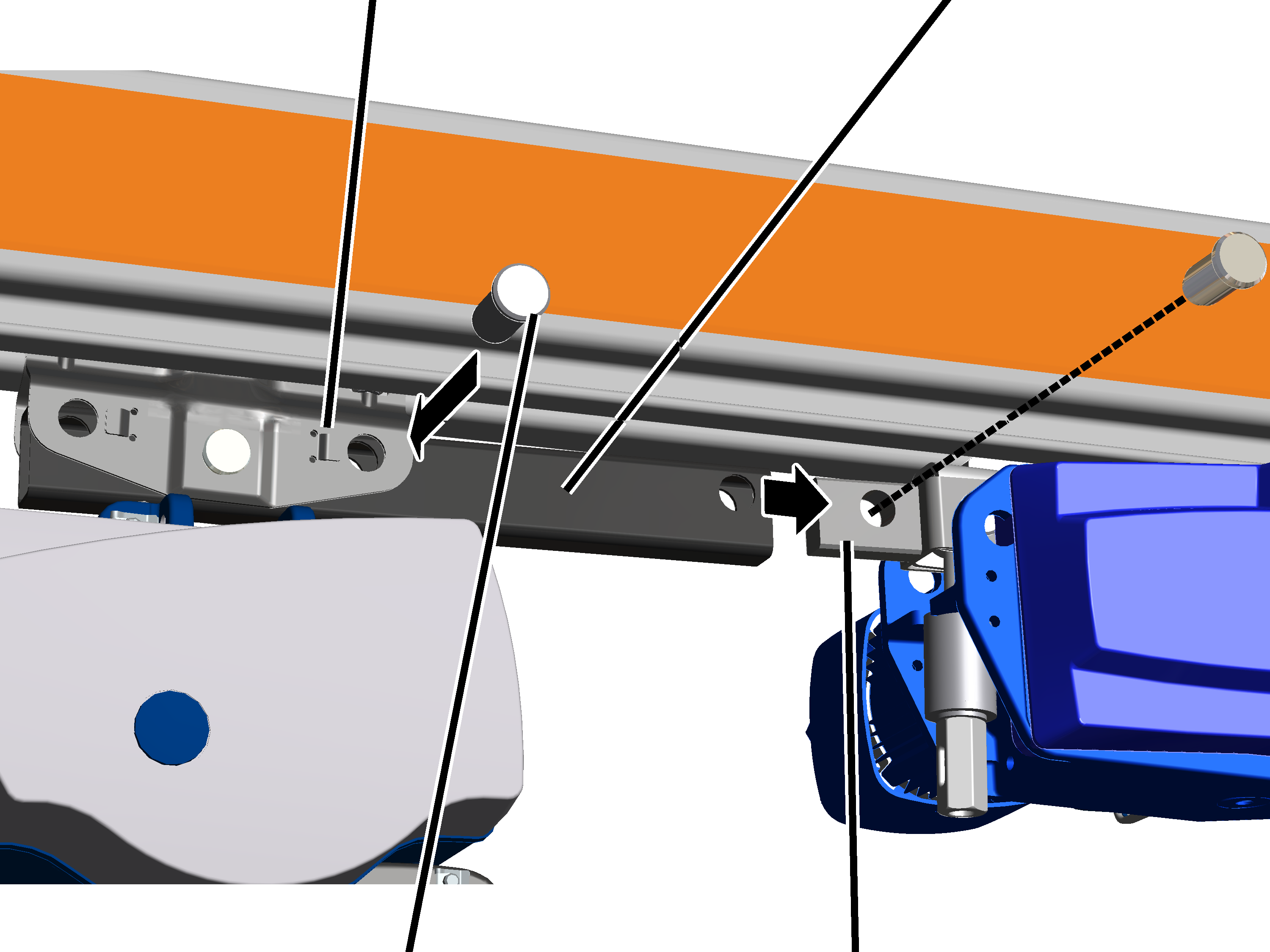
- On the crane trolley or hoist trolley: push the coupling bar inside the trolley.
- Push bolts (1x) through trolley and coupling bar.
- Secure bolt with SL safety clips (1x).
- On the HBF drive: push the coupling bar over the coupling.
- Push the bolt through the coupling bar and coupling.
- Secure bolt with SL safety clip.
Only with free-running anti-collision device
Connecting trolleys
Trolleys for anti-collision device
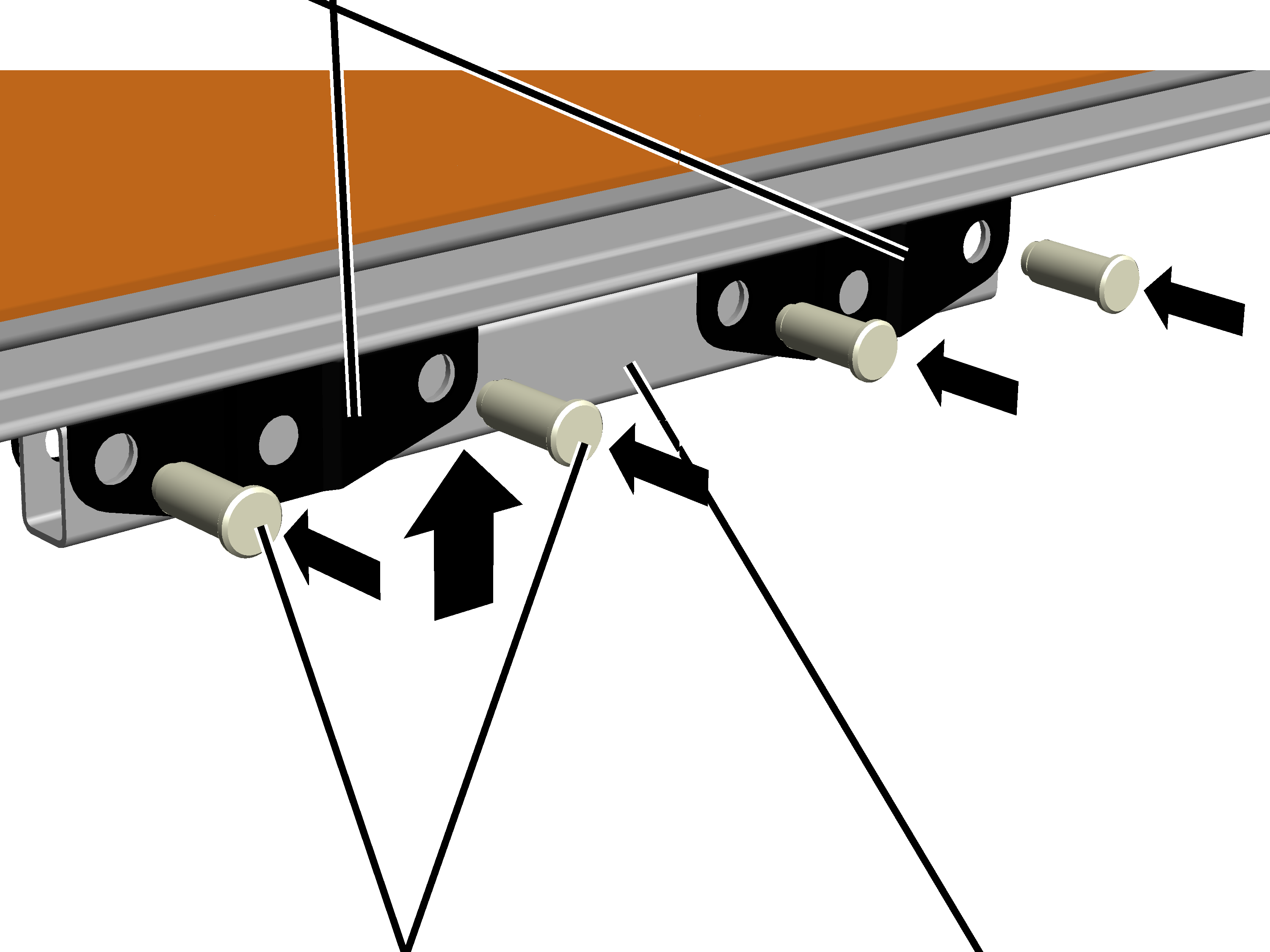
- Push the coupling bar between the trolleys.
- Push bolts (4x) through trolley and coupling bar.
- Secure bolts with SL safety clips (4x).
Only for anti-collision device with coupling bar
Connecting trolleys
Bolt
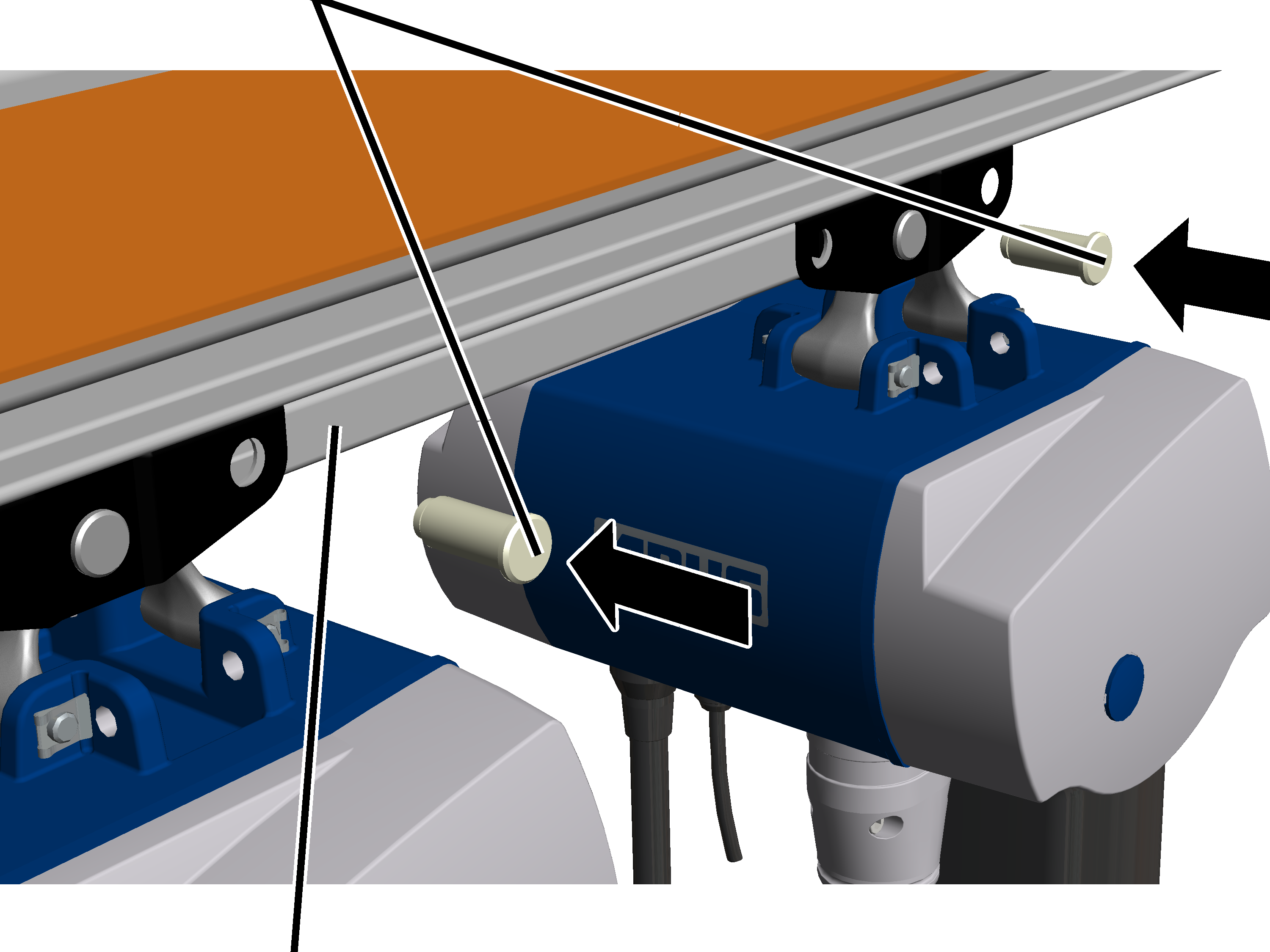
- Push the coupling bar between the trolleys.
- Push bolts (2x) through trolley and coupling bar.
- Secure bolts with SL safety clips (2x).
Installing the festoon cable system
Installing the travel stop
The cable marshalling point (the profile end on which the festoon cable system is pushed together by the trolley) must be installed with a travel stop. This prevents the trolley from running to the very end of the HB profile rail and impacting the cable marshalling point with the cable sliders.
Installing the travel stop at the cable marshalling point:
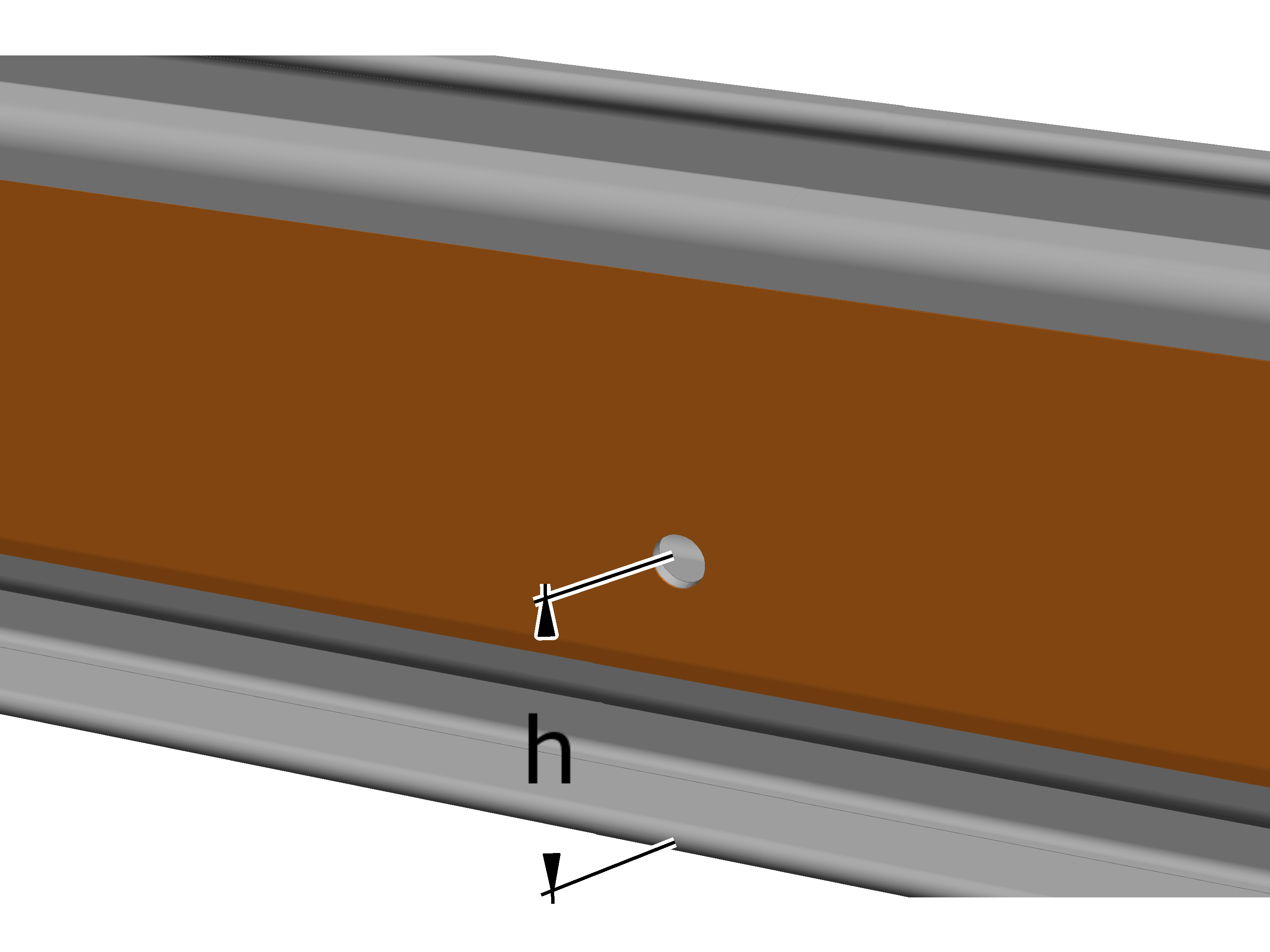
- Drill a hole in the profile rail section on both sides for the travel stop:
- Distance from the profile end: as calculated or taken from the planning documents.
- Diameter 12 mm.
- Distance to lower edge
Size |
Distance |
|---|---|
HB110 |
53 mm |
HB150 |
73 mm |
HB190 |
73 mm |
HB240 |
73 mm |
- If the travel stop lies in the area of a profile joint: drill through both the profile rail section as well as the clamping plates.
- Deburr the drilled holes.
- Thoroughly remove any saw or drill shavings.
Otherwise the shavings can clog the castors of the trolleys and impair their running.
SL safety clip
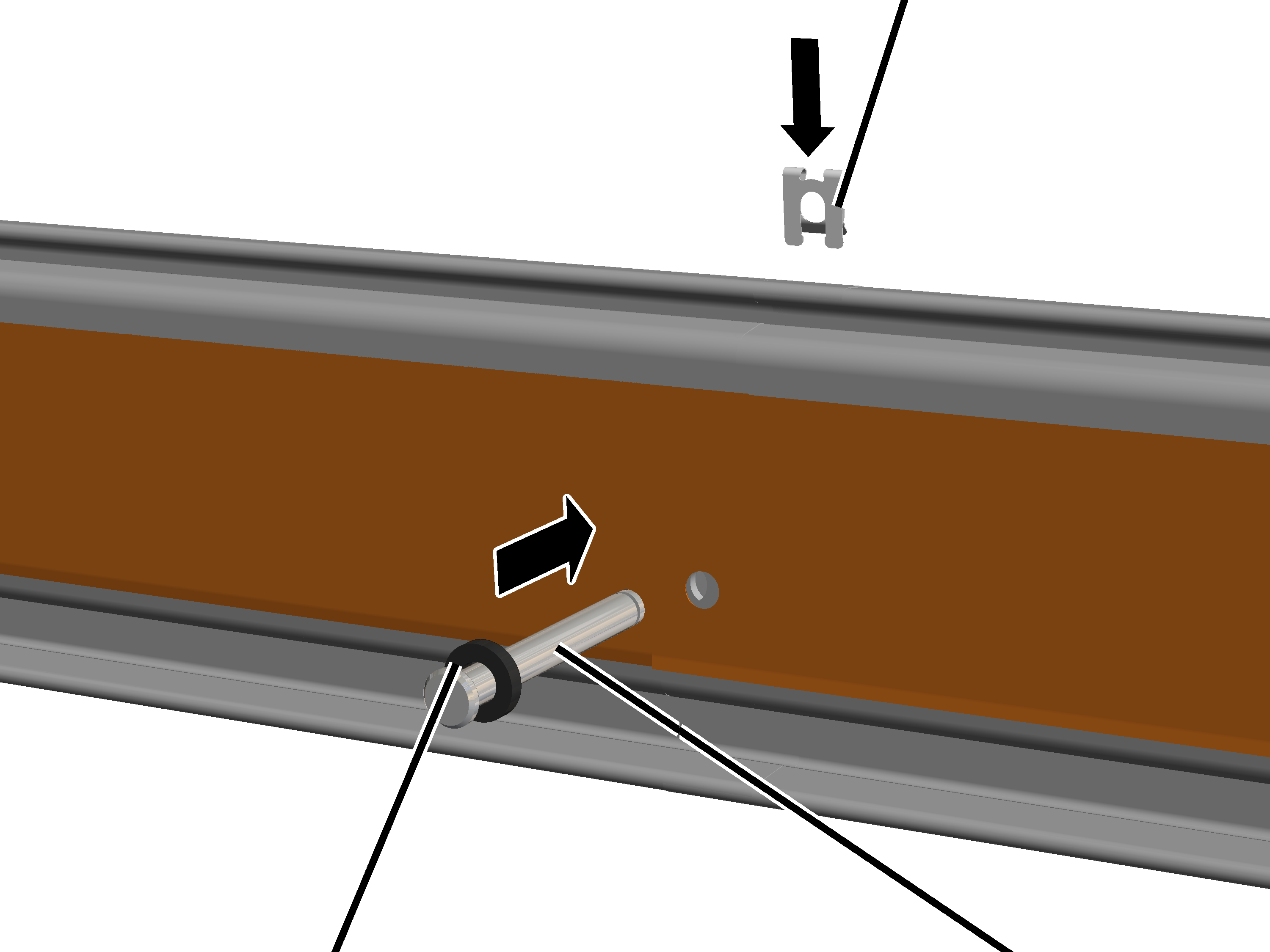
- If the travel stop lies in the area of a profile joint: insert the bolt through the HB profile rail.
- If the travel stop lies on a free profile rail section: place a spacer disc on the bolt and insert the bolt through the HB profile rail.
- Secure bolt with SL safety clip.
Inserting cable sliders
Calculate the number of cable sliders:
- Read off the cable sag from the crane drawing.
- Calculate and round off the number of cable sliders.
Length of the crane track or HB crane runway |
||
|---|---|---|
Number = |
- 1 |
|
(cable sag x 2) |
Insert cable sliders:
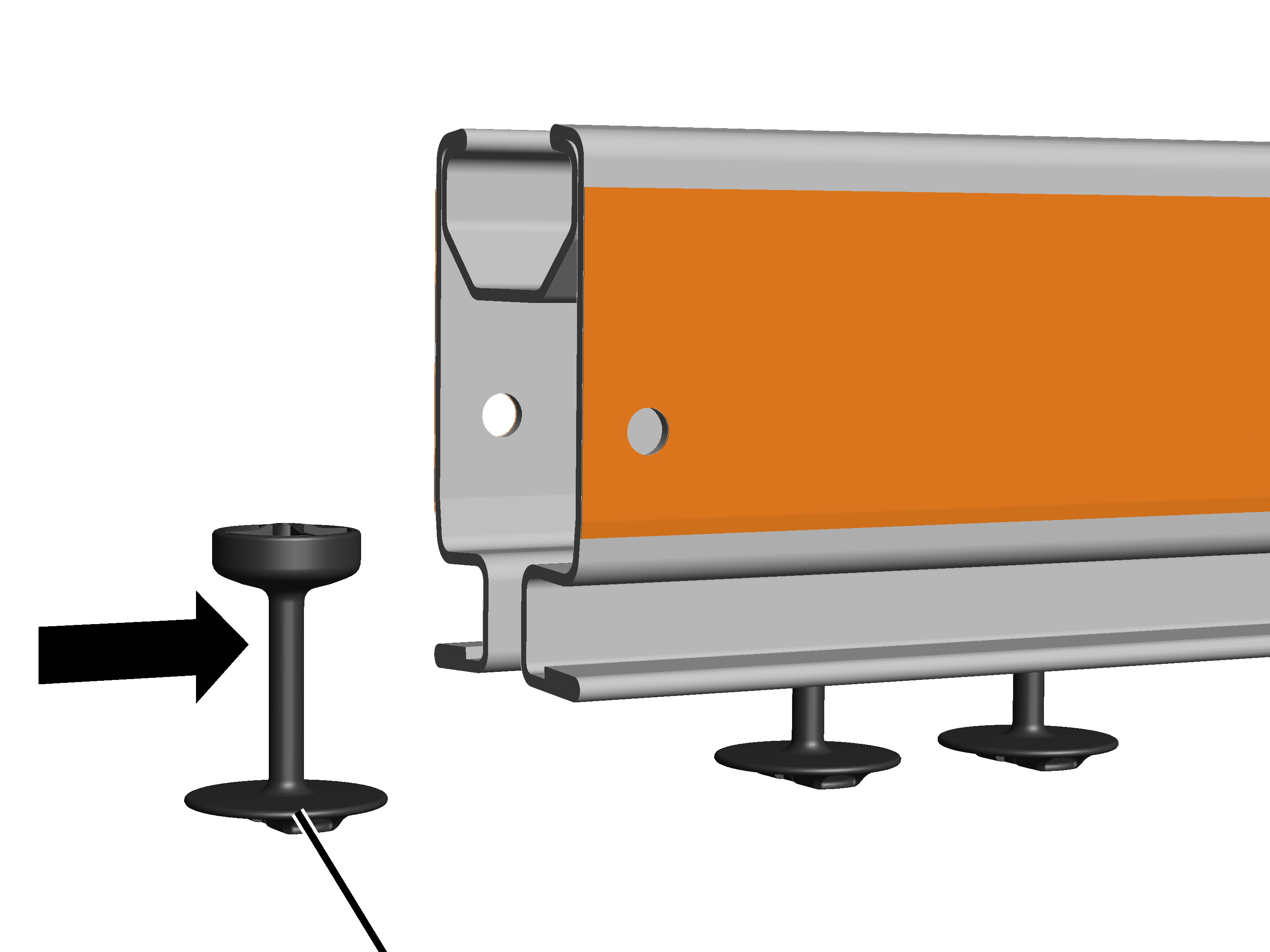
- Insert the corresponding number of cable sliders.
Installing the festoon cable system on the trolley
On the trolley lying in the direction of the power supply:
Cable supportBracket
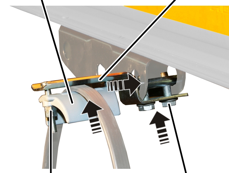
- Screw the bracket onto the trolley with the M8x25 rib screw. 20 Nm.
- Press the festoon cable system with cable support against the bracket. Screw tight with M6x40 hexagon head screws (2x) and M6 hexagonal nuts (2x).
- Lock with M6 hexagonal nuts (2x).
Fastening the festoon cable system on cable sliders
Cable sag x 2
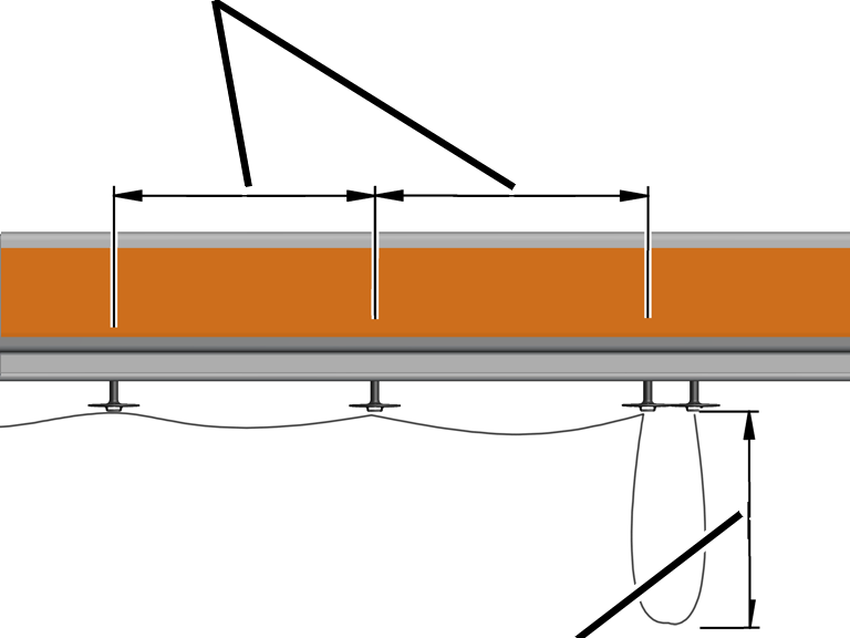
- Lay the festoon cable system from the end of the HB profile rail and fasten loosely at first with cable clips on the cable sliders.
For narrow, individual flat cables, push the cable clips in the narrow opening on the cable slider. For wide or multiple cables, use the wide opening.
- Position the cable sliders in such a way that two cable sliders are twice the cable sag away from one another.
The cable sag (usually 800 m) is specified on the crane drawing.
Depending on the total length of the flat cable, the cable sliders can also lie closer together. The spacing between all cable sliders should nevertheless remain the same.
- Tighten the cable clips.
Installing the festoon cable system on the profile end
Every HB profile rail must be fitted with end caps on the profile ends. These prevent dirt from penetrating the HB profile rail and also serve as an end stopper to prevent the HB crane or trolley from falling out of the HB profile rail.
The end cap remains the fixed point of the festoon cable system.
On the HB profile rail with festoon cable system:
End cap
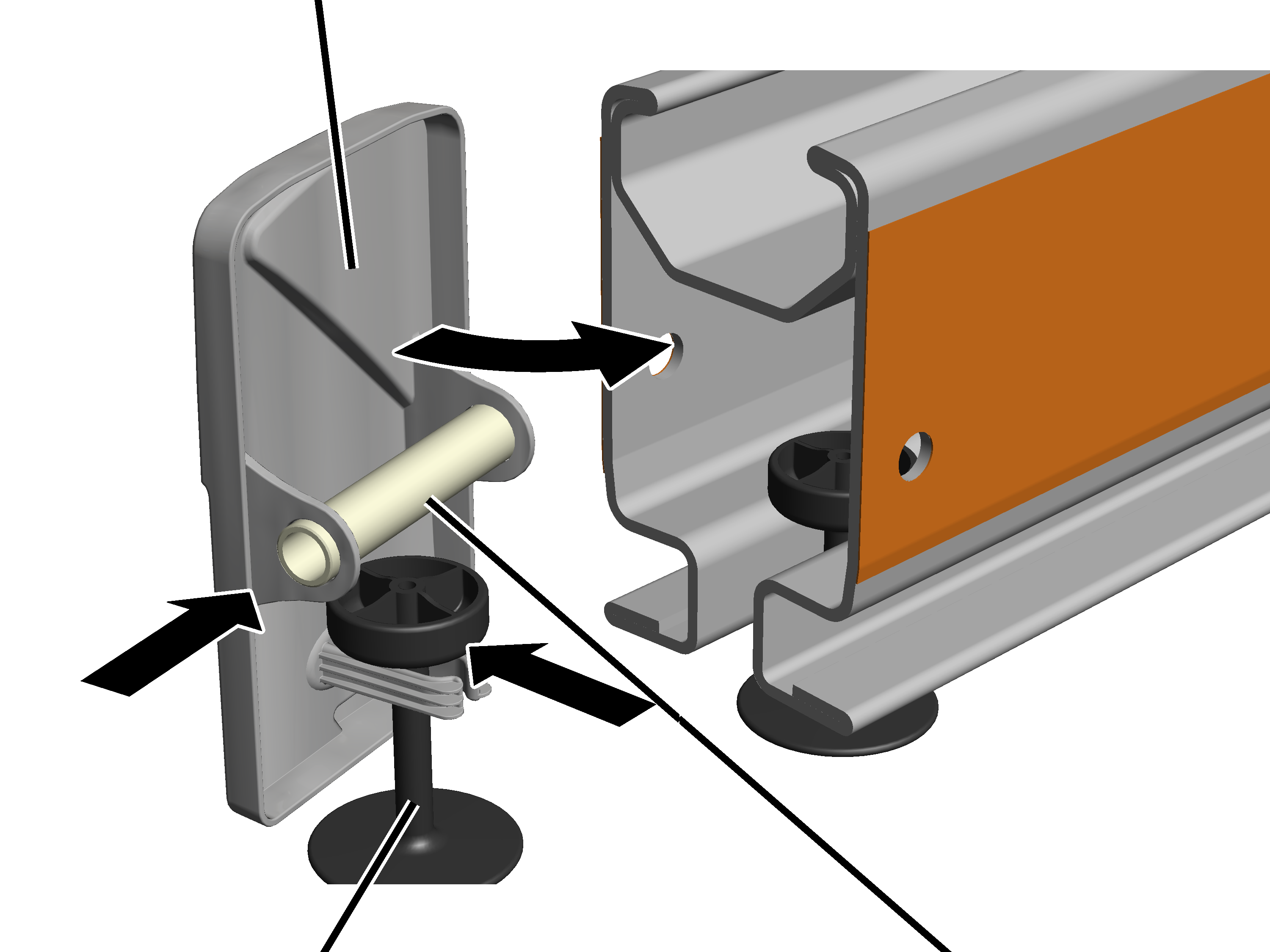
- Insert cable sliders on the end cap.
- Push the spacer sleeve into the end cap.
Only with HB240: use the spacer sleeve with black coating. It is slightly longer than the spacer sleeve with silver or yellow coating.
- Put on the end cap.
If necessary, widen the HB profile rail slightly to enable insertion of the spacer sleeve.
Hexagon head screw
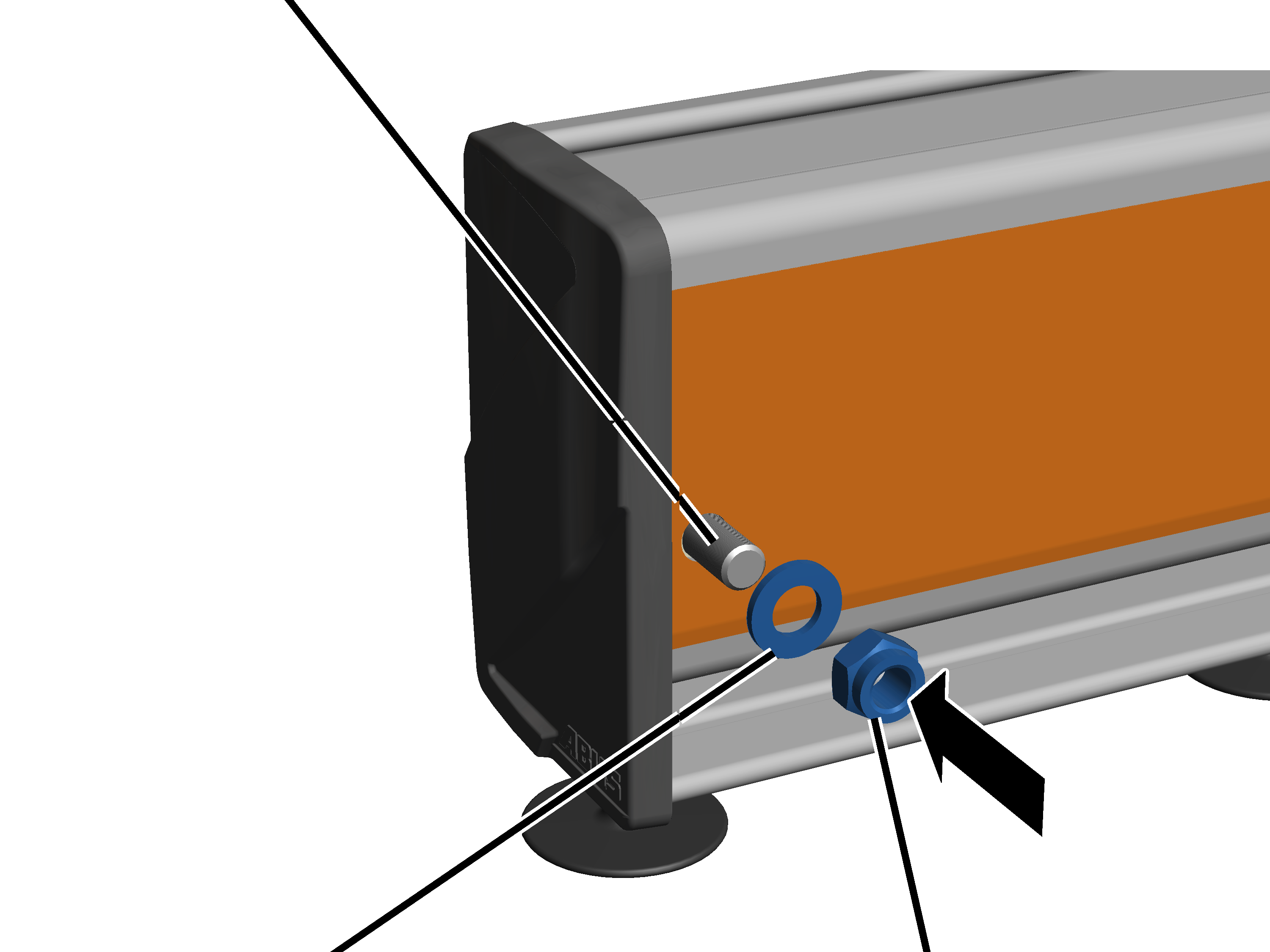
- Insert a hexagon head screw through the HB profile rail and the spacer sleeve.
Size |
Hexagon head screw |
|---|---|
HB110 |
M12x85 |
HB150 |
M12x110 |
HB190 |
M12x110 |
HB240 |
M12x110 |
- Insert washer, screw on the self-locking M12 nut and tighten to 80 Nm.
- Fasten the flat cable as before on the fixed cable slider.
Fitting the end caps
On all other HB profile rails:
End cap
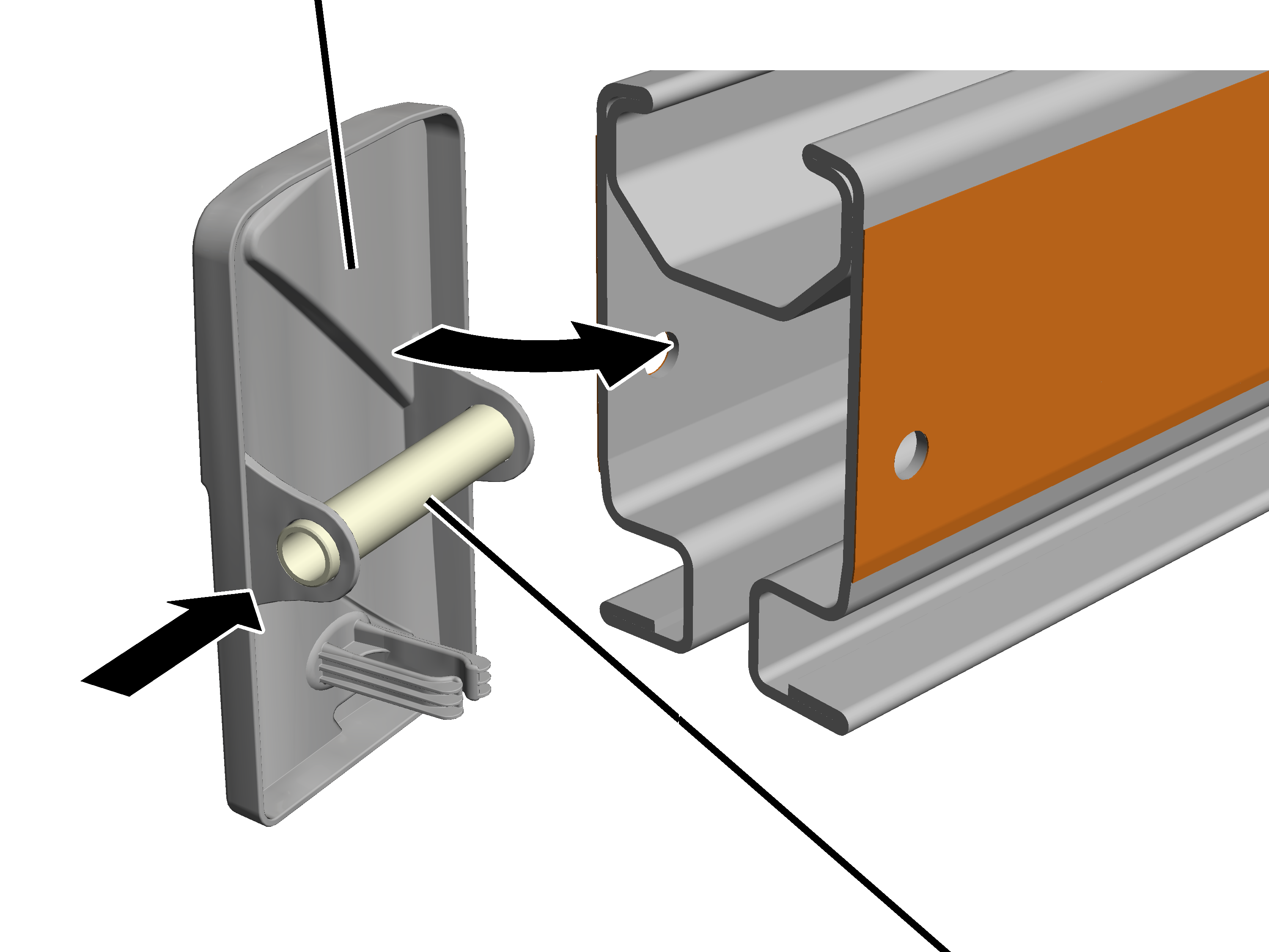
- Push the spacer sleeve into the end cap.
Only with HB240: use the spacer sleeve with black coating. It is slightly longer than the spacer sleeve with silver or yellow coating.
- Put on the end cap.
If necessary, widen the HB profile rail slightly to enable insertion of the spacer sleeve.
Hexagon head screw
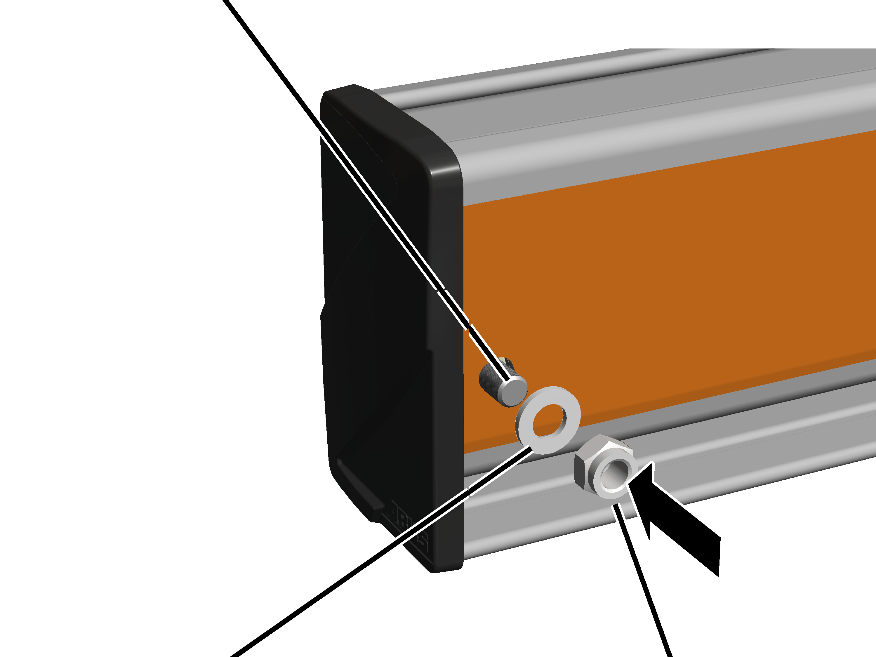
- Insert a hexagon head screw through the HB profile rail and the spacer sleeve.
Size |
Hexagon head screw |
|---|---|
HB110 |
M12x85 |
HB150 |
M12x110 |
HB190 |
M12x110 |
HB240 |
M12x110 |
- Insert washer, screw on the self-locking M12 nut and tighten to 80 Nm.
Installing the conductor system VKL
Installing brackets on the HB profile rail
The conductor system VKL is installed on the profile head of the HB profile rail with brackets.
Only with HB110S
On each support:
Clamping elementRib screw M8x30
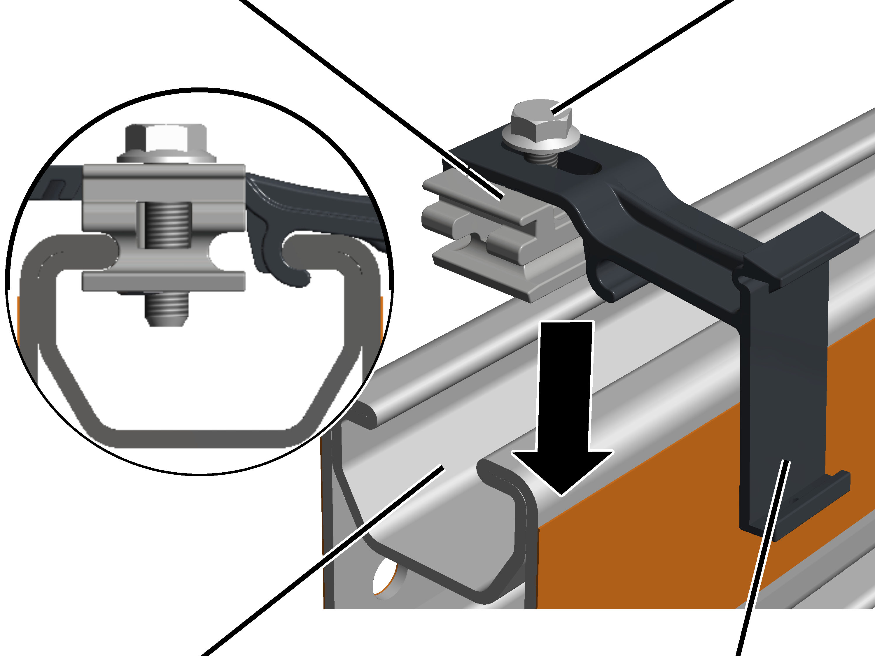
- Turn the clamping element as shown in the diagram.
- Insert the bracket in the profile head from above.
- Screw the M8x30 rib screw tight.
Only with HB150S and HB190S
On each support:
Clamping elementRib screw M8x30
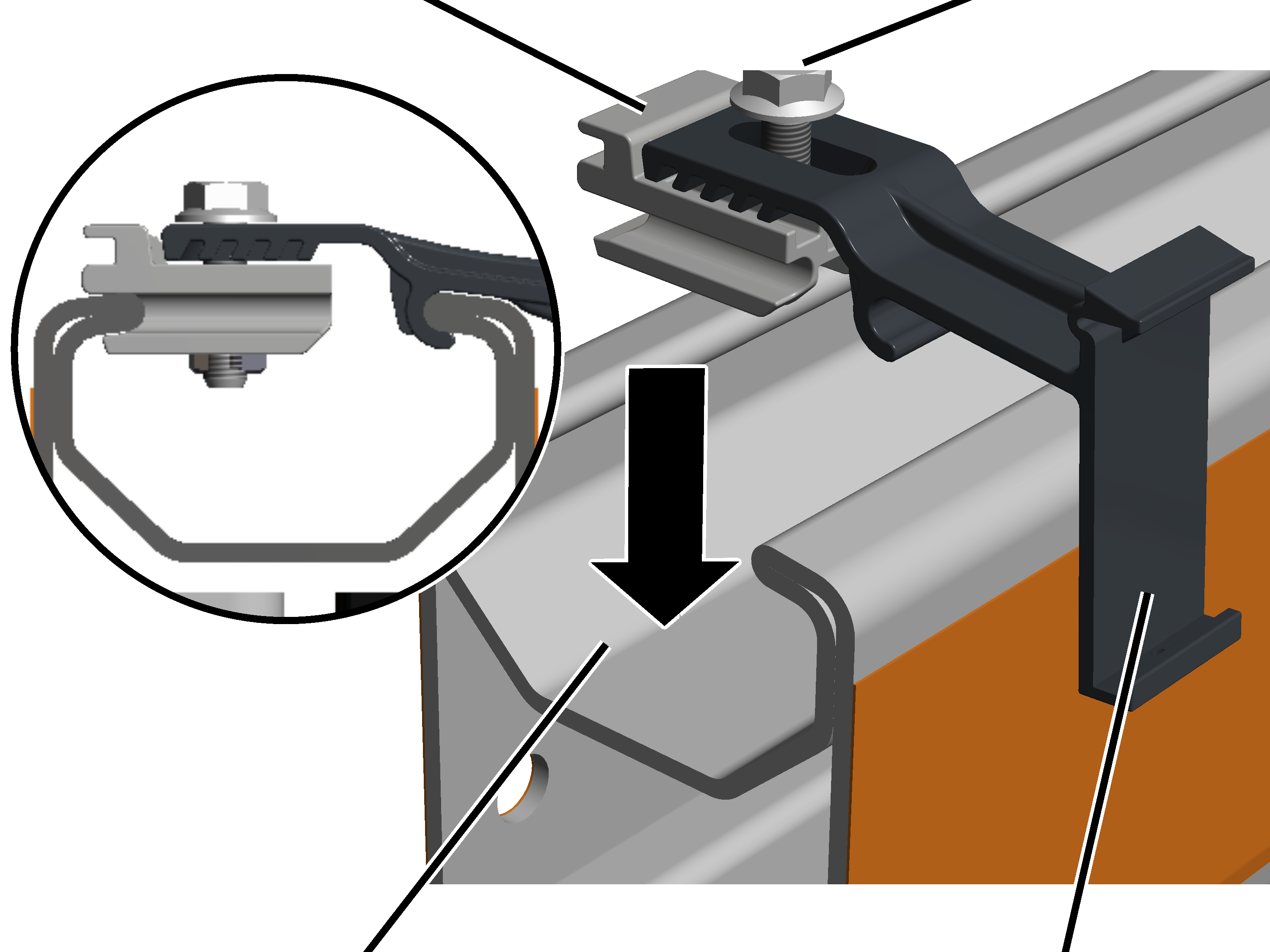
- Turn the clamping element as shown in the diagram.
- Insert the bracket in the profile head from above.
- Screw the M8x30 rib screw tight.
Only with HB240
This section only applies to a VKL conductor system on the crane girder.
On each support:
Head nutBracket
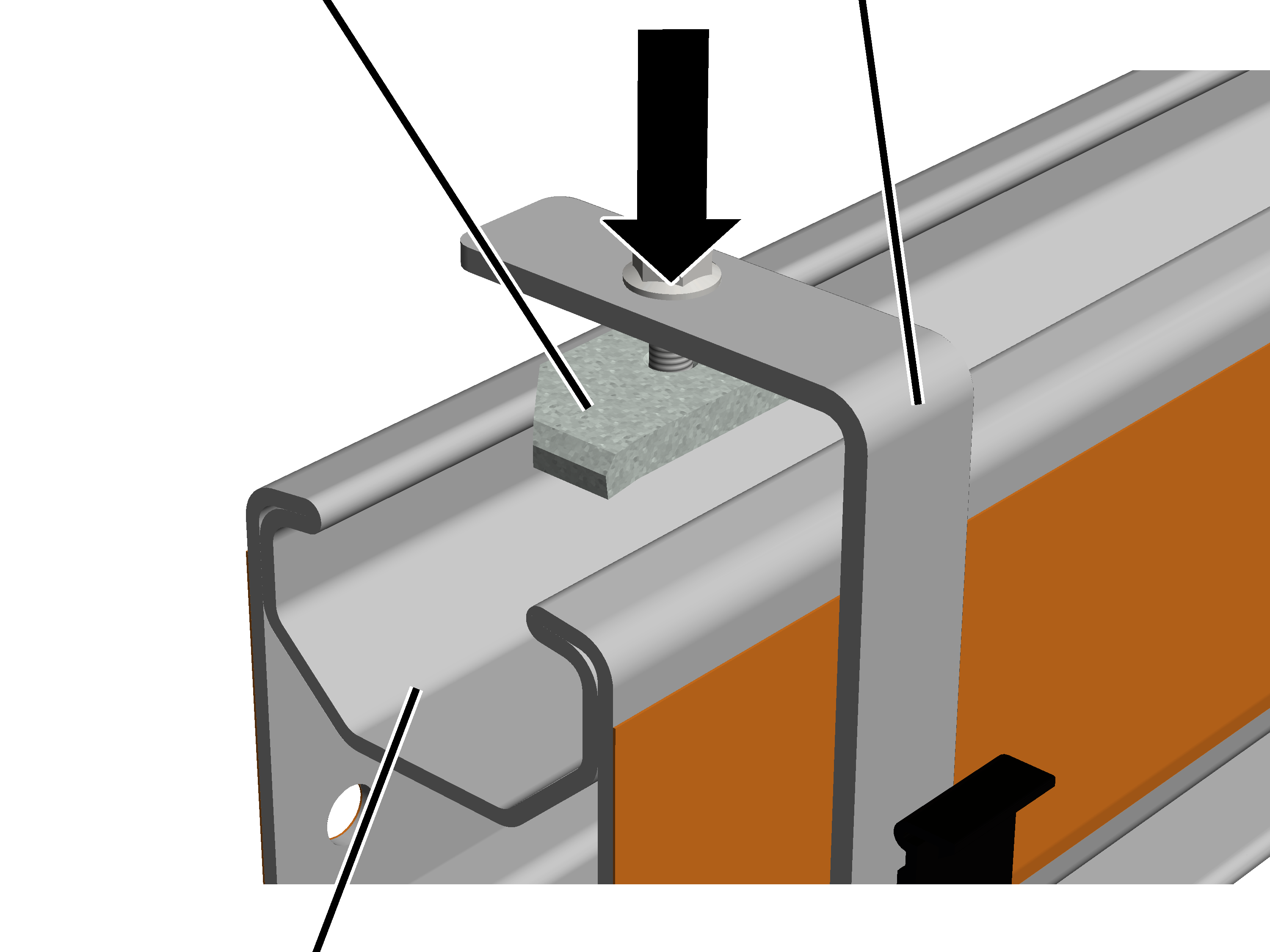
- Turn the head nut in the longitudinal direction and lay the support on the profile head from above.
- The head nut extends into the profile head.
- Tighten the rib screws to 25 Nm.
- The head nut turns during fixing in the crosswise direction and is clamped tight in the profile head.
Preparing sections
- Lay out the individual sections of the conductor system on the floor as they will later be installed on the HB profile rail.
Installing sections
For every section:
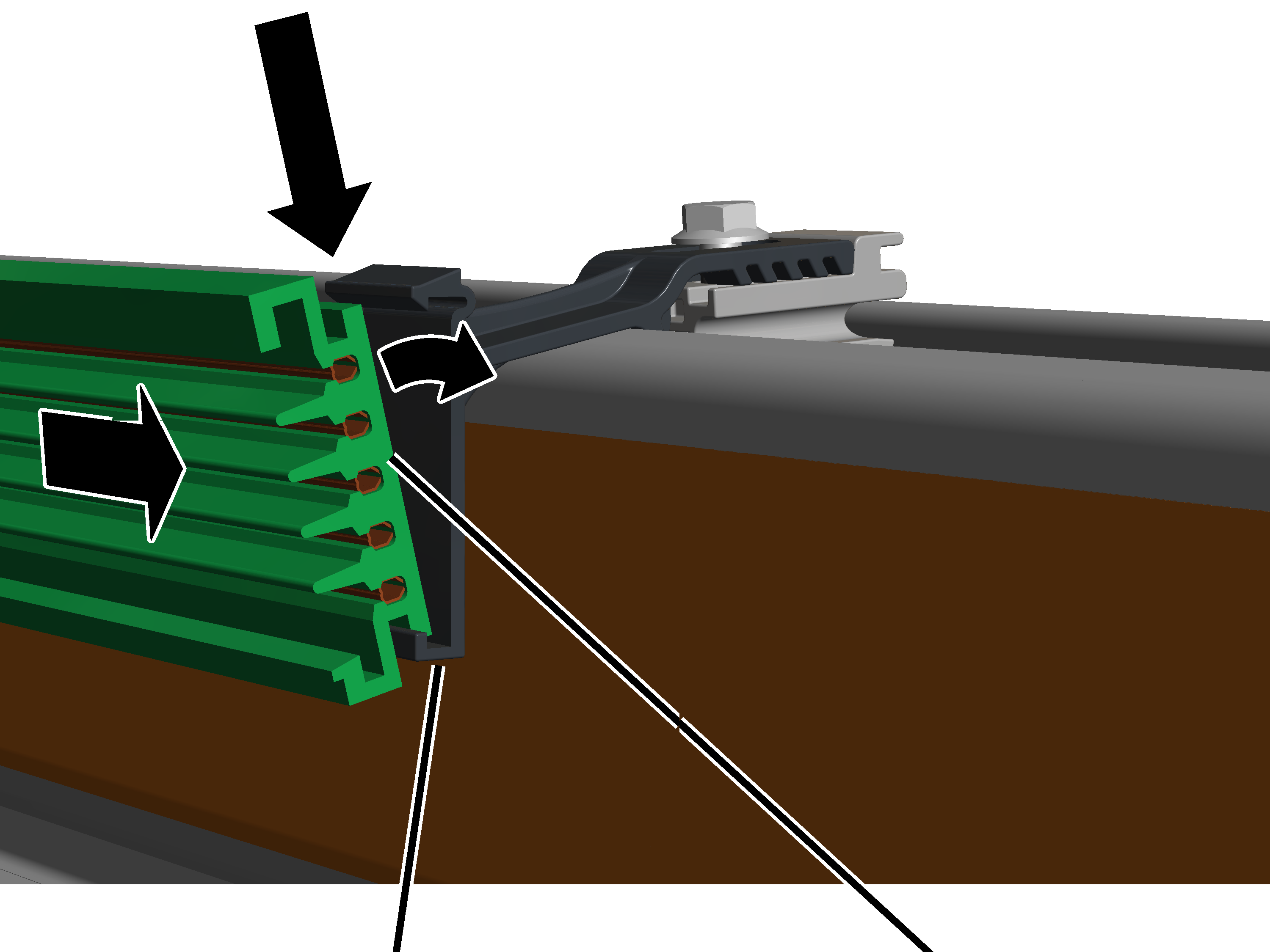
- Insert the section bottom in the bracket and latch it at the top.
Installing the feed unit
Feed unit
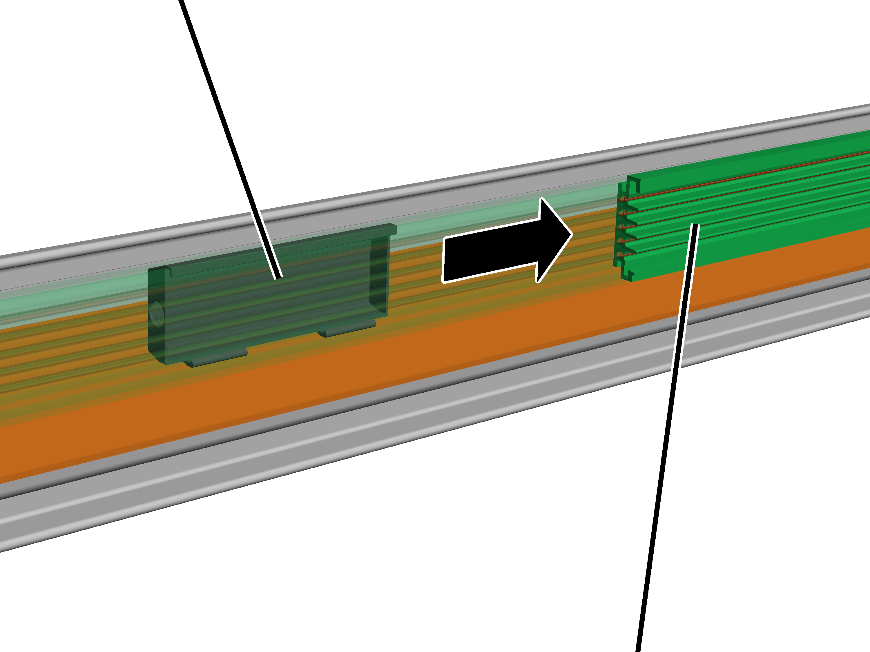
- Install the feed unit at the location specified in the planning documents.
The feed unit is fixedly installed on a one-metre long section. This is installed as a regular section.
Connecting the sections electrically
The sections are electrically connected with one another by means of connecting pins.
At every joint:
Connecting pinsSection
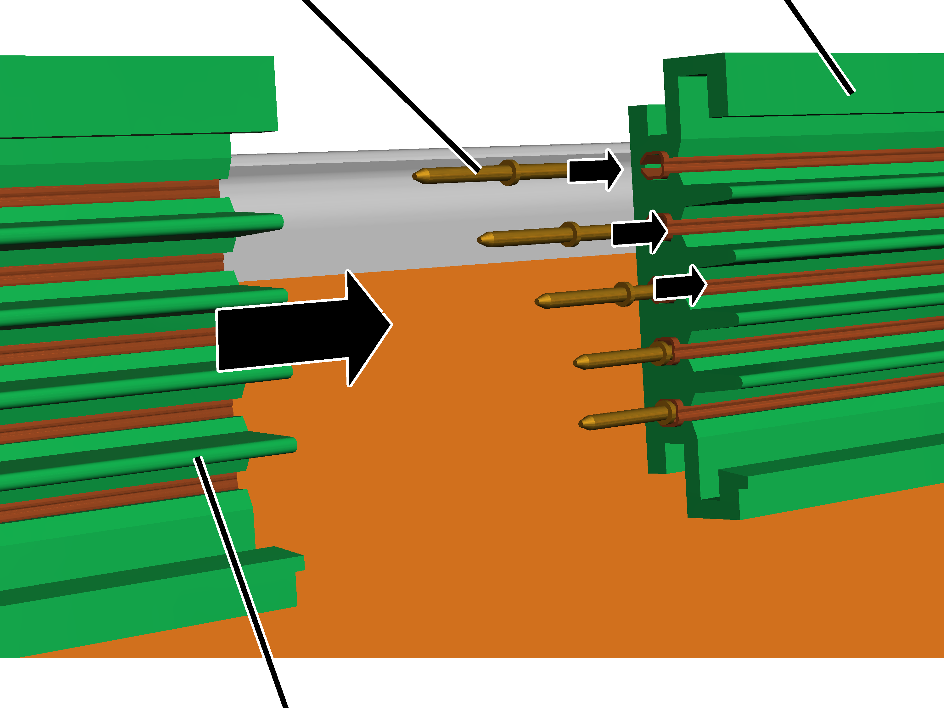
- Insert the connecting pins laterally in the rails of a section.
Insert the connecting pins in the rails preferably at varying depths. This will facilitate the positioning of the next section.
- Push the section up to the previous section.
- Insert the connecting pins of the previous section into the rails of the next section.
- Place a wood block at the end of a section and use hammer to strike the section against the previous one.
- The connecting pins are inserted fully into the rail and are no longer visible.
Tip:
To prevent the conductor system slipping away during striking, fix the first section to the HB profile rail. To do this push a suitable piece of wood between the conductor system and the HB profile rail, place a second piece of wood on the conductor system and fix in place using a screw clamp.
Connecting the sections mechanically
A two-piece connector can also be used to connect the sections with each other mechanically.
At every joint:
Connector
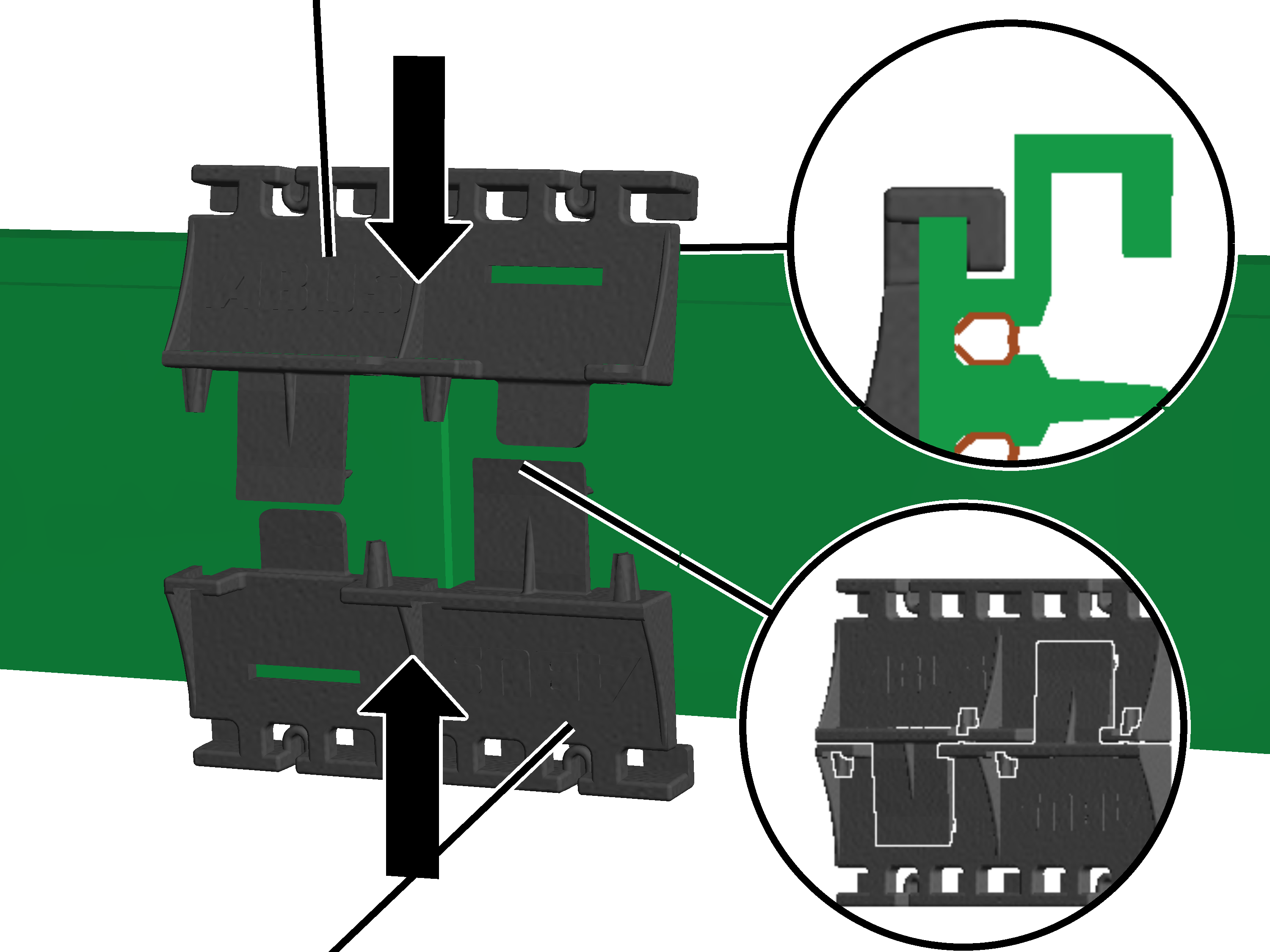
- Push the halves of the connector onto the conductor system from above and below.
The two halves for top and bottom are identical.
- Align the connectors so that the plastic lugs slip precisely into the undercut on the conductor system.
- Insert the connectors into one another behind the conductor system.
Fixing the conductor system
One of the sections is now fixed to the bracket. The other sections remain loosely latched. This allows the entire conductor system to freely expand or contract when temperatures change. However, due to the one fixedly bolted section, the entire conductor system cannot slide into the brackets.
The section to be bolted should lie about in the middle (within the span of the conductor system).
Centred within the span of the conductor system:
BracketSection
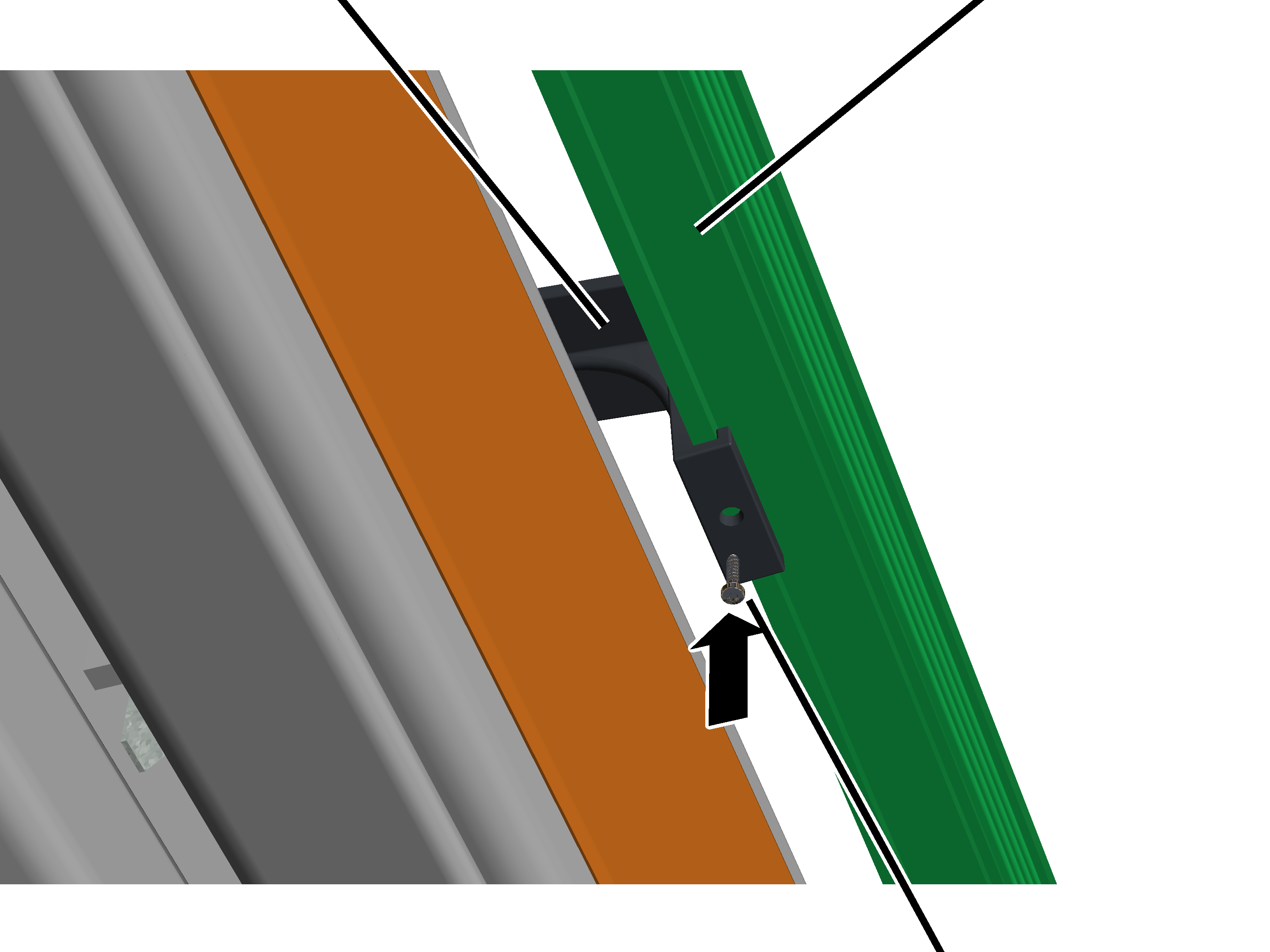
- Screw the self-tapping screw from below into the bracket and section.
Inserting the current collector
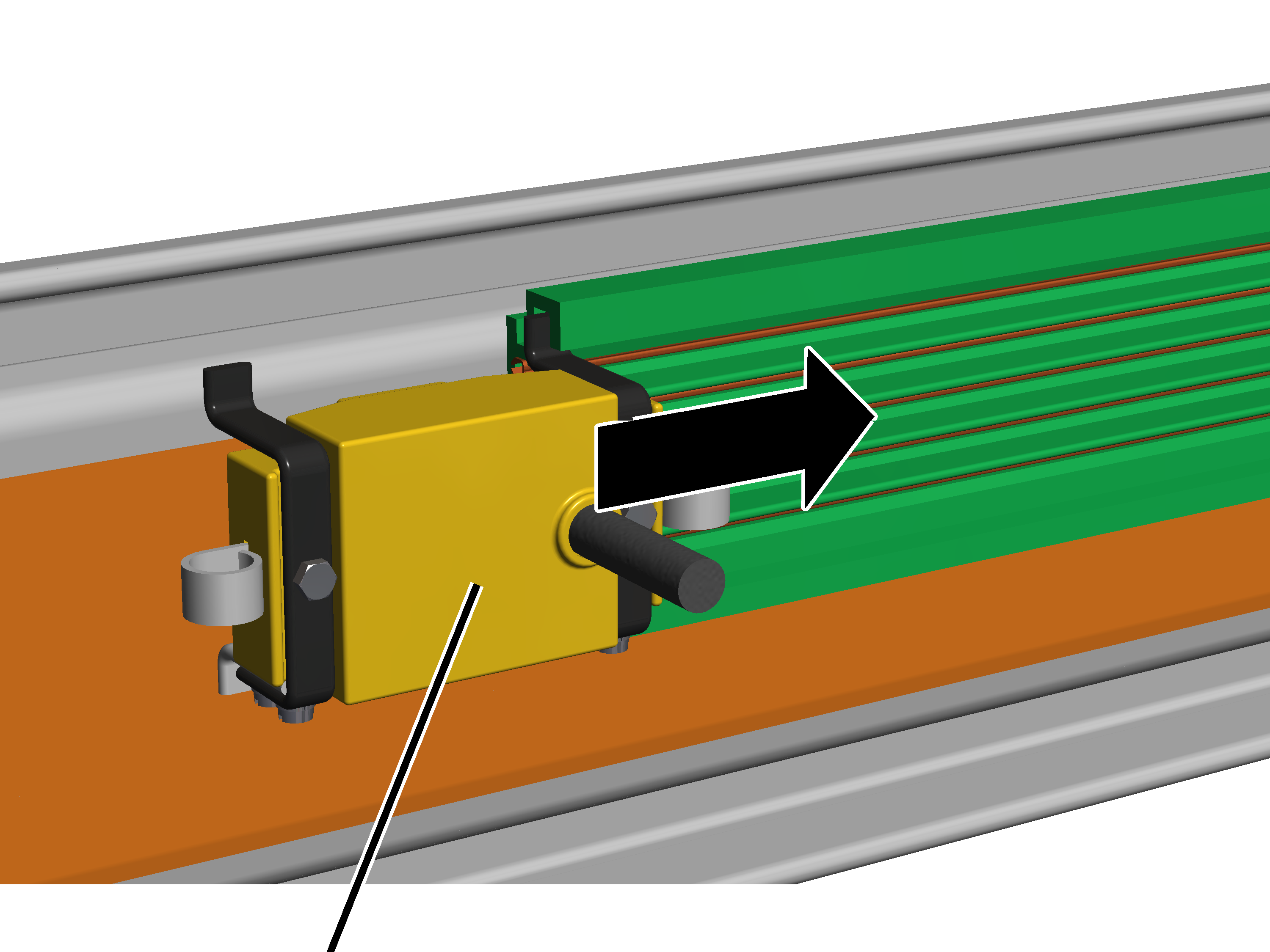
- Slide the current collector into the conductor system.
- Slide the current collector over the entire length of the conductor system to test it.
The current collector must move smoothly and not get caught, particularly at the joints.
Installing the power carrier
On the trolley:
The carrier shaft can also be installed in drilled holes on which other attached components (e.g. anti-collision device or HBF drive / travel drive) have already been installed. In this case, remove the installed bolt and mount the attached component with the carrier shaft.
Only with trolley with integrated anti-rotation device
This work step is only applicable if the trolley has a protruding nose next to the drilled hole as an integrated anti-rotation device.
Integrated anti-rotation device
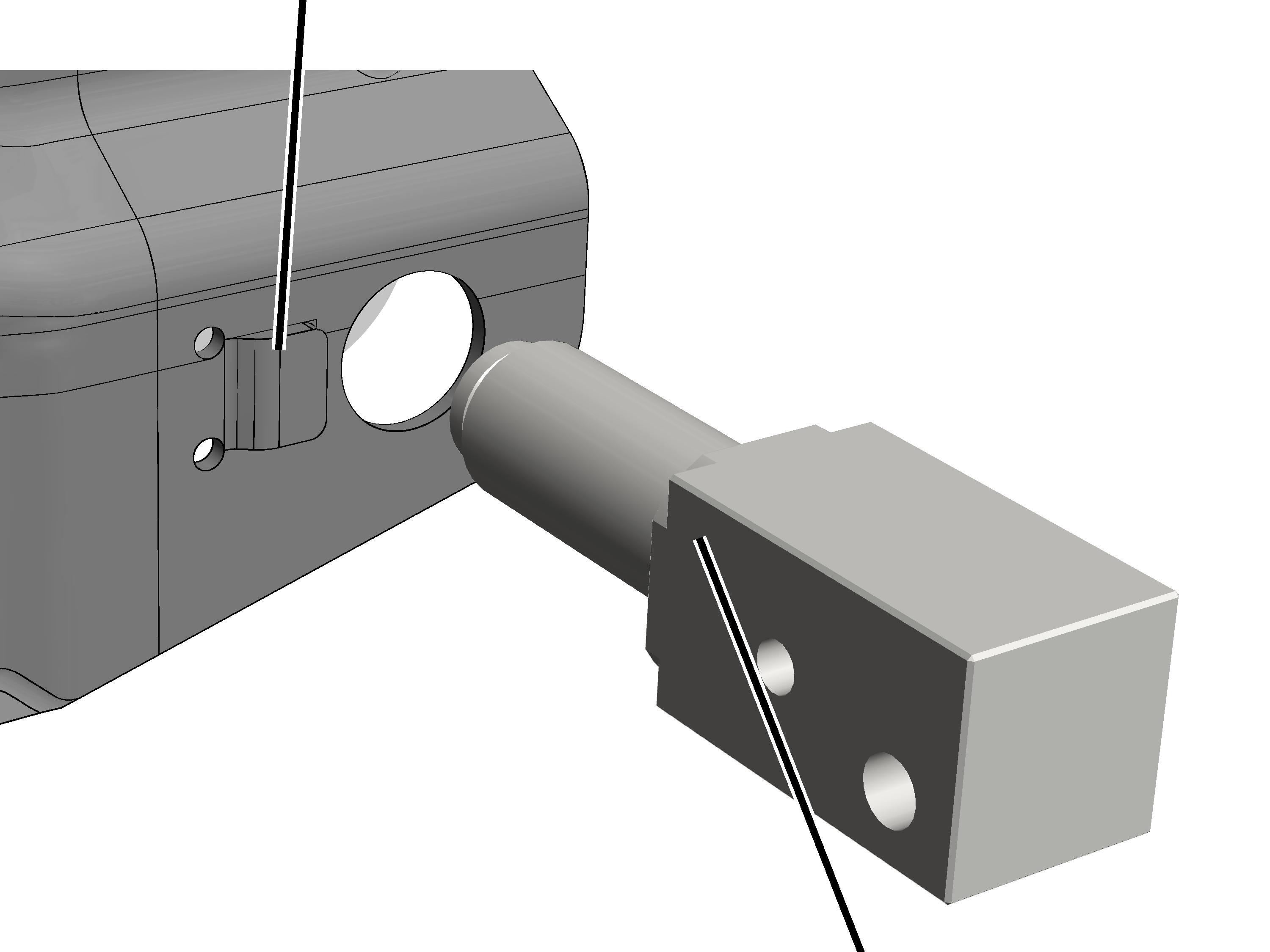
- Push the carrier shaft directly into the drilled hole on the trolley.
Do not use the included separate anti-rotation device!
- The carrier shaft is secured on the trolley by means of an integrated anti-rotation device and cannot turn.
Only with trolley without integrated anti-rotation device
This work step is only applicable if the trolley does not have an integrated anti-rotation device.
Separate anti-rotation device
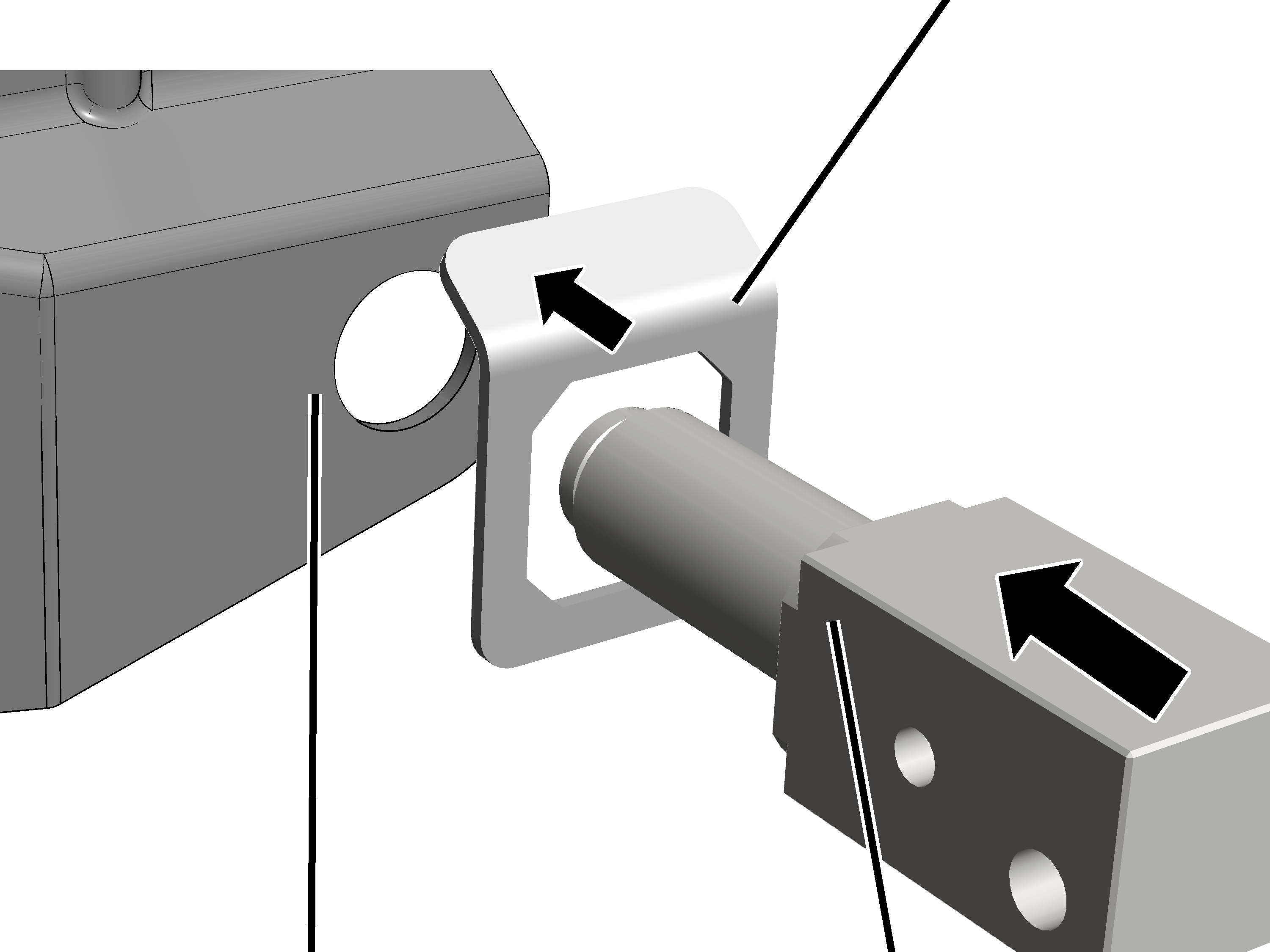
- Place the separate anti-rotation device over the drilled hole on the trolley.
- Push the carrier shaft through the separate anti-rotation device into the drilled hole on the trolley.
- The carrier shaft is secured on the trolley by means of the separate anti-rotation device and cannot turn.
Right drilled hole on the trolleyOuter drilled hole
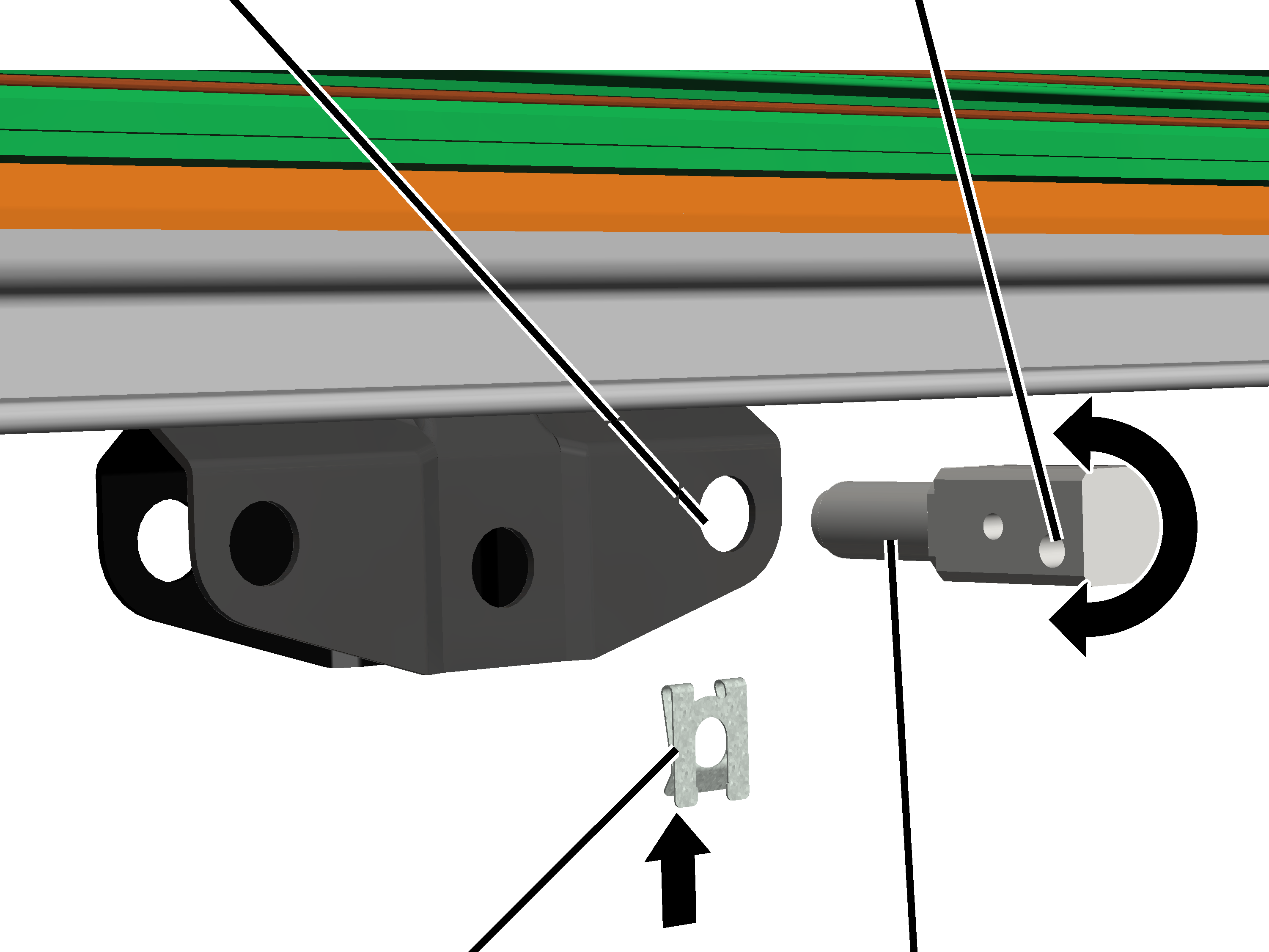
- Turn the carrier shaft with the outer drilled hole toward the top or toward the bottom.
Size |
Outer drilled hole in the carrier shaft |
|---|---|
HB240S |
Toward the top |
HB190A HB190S |
Toward the top |
HB150A HB150S |
Toward the bottom |
HB110S |
Toward the bottom |
- Insert the SL safety clip.
Right eyelet on the current collectorTowing mandrel
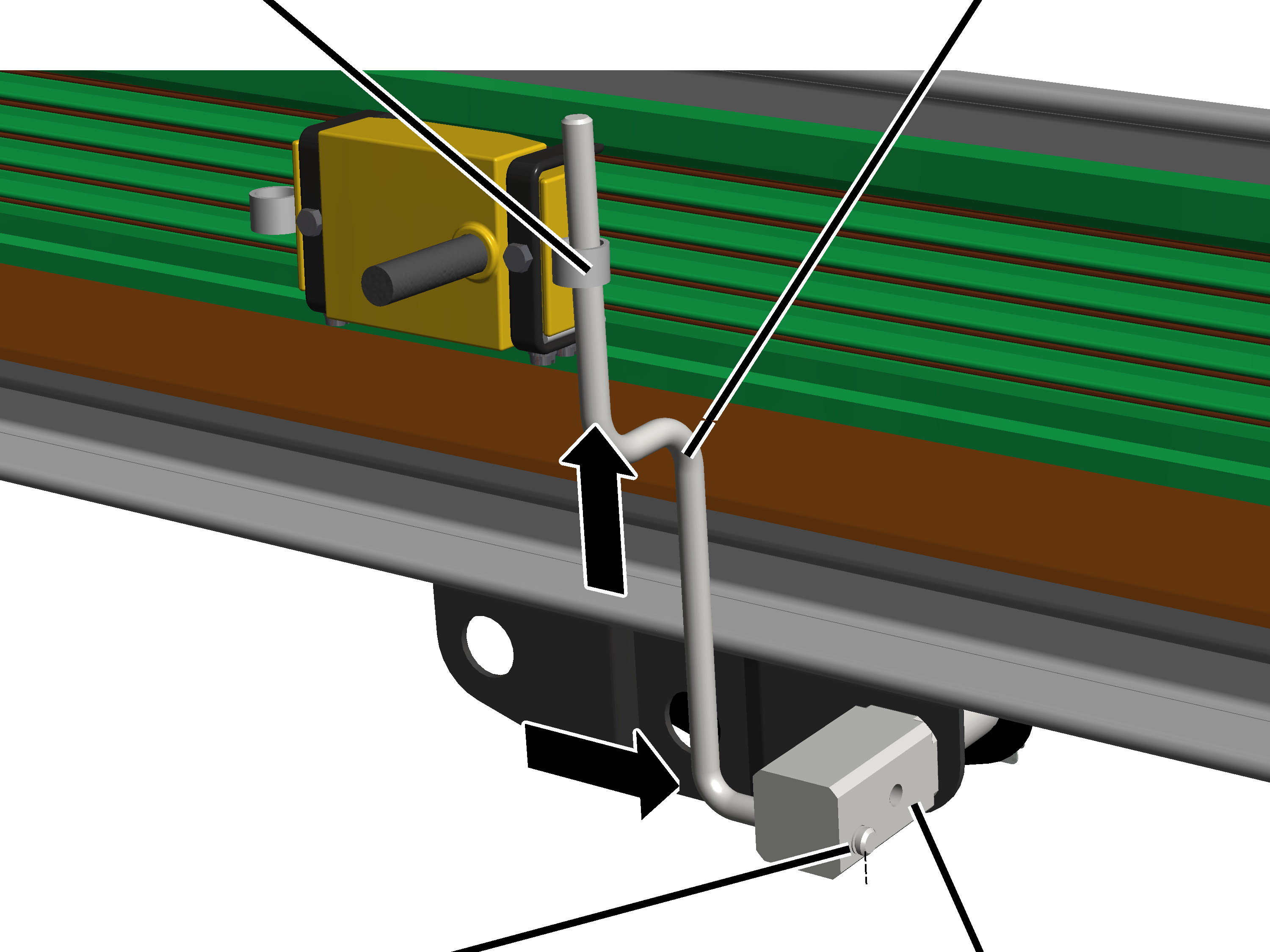
- Rotate the towing mandrel as in the diagram.
- Insert the towing mandrel from below into the right eyelet on the current collector.
- Insert the towing mandrel from the left into the outer hole in the carrier shaft.
- Secure the towing mandrel with the SL safety clip.
Tip:
The assembly described above ensures that the current collector is positioned centred over the trolley. The current collector will therefore not bump against the end of the HB profile rail.
Summary:
- Insert the carrier shaft into the right drilled hole on the trolley.
- Insert the towing mandrel from the left into the carrier shaft.
- Insert the towing mandrel into the right eyelet on the current collector.
Shortening the towing mandrel
Depending on the crane installation, the towing mandrel may protrude at the top over the conductor system VKL. If the towing mandrel causes problems (e.g. catches on things), it must be shortened.
If the towing mandrel protrudes at the top and is a problem:
Protruding towing mandrel
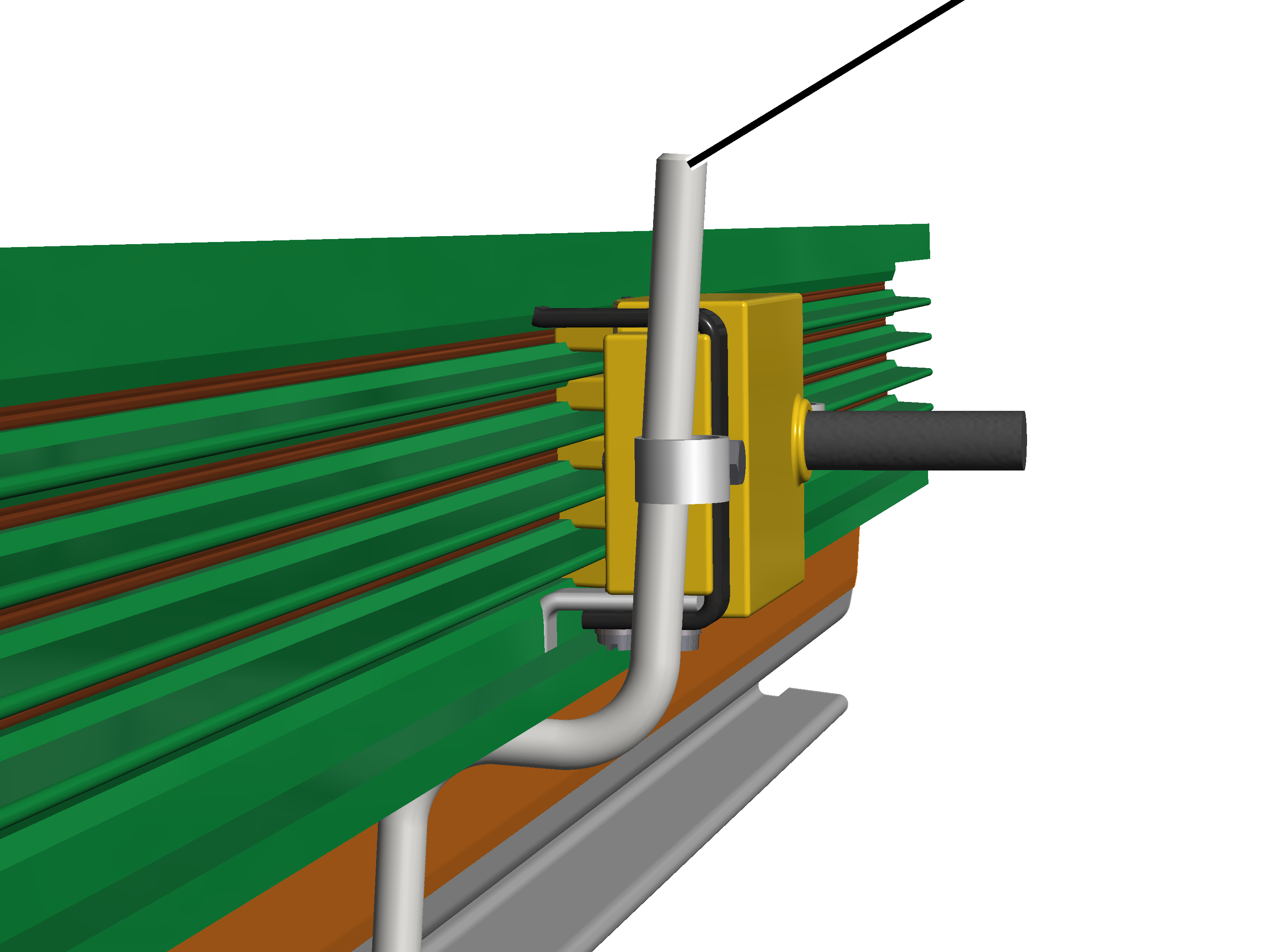
- Saw or cut off the end of the towing mandrel.
On the towing mandrel is a notch to be used for shortening it.
Fitting the retaining caps on the conductor system
On both ends of the conductor system:
Retaining cap
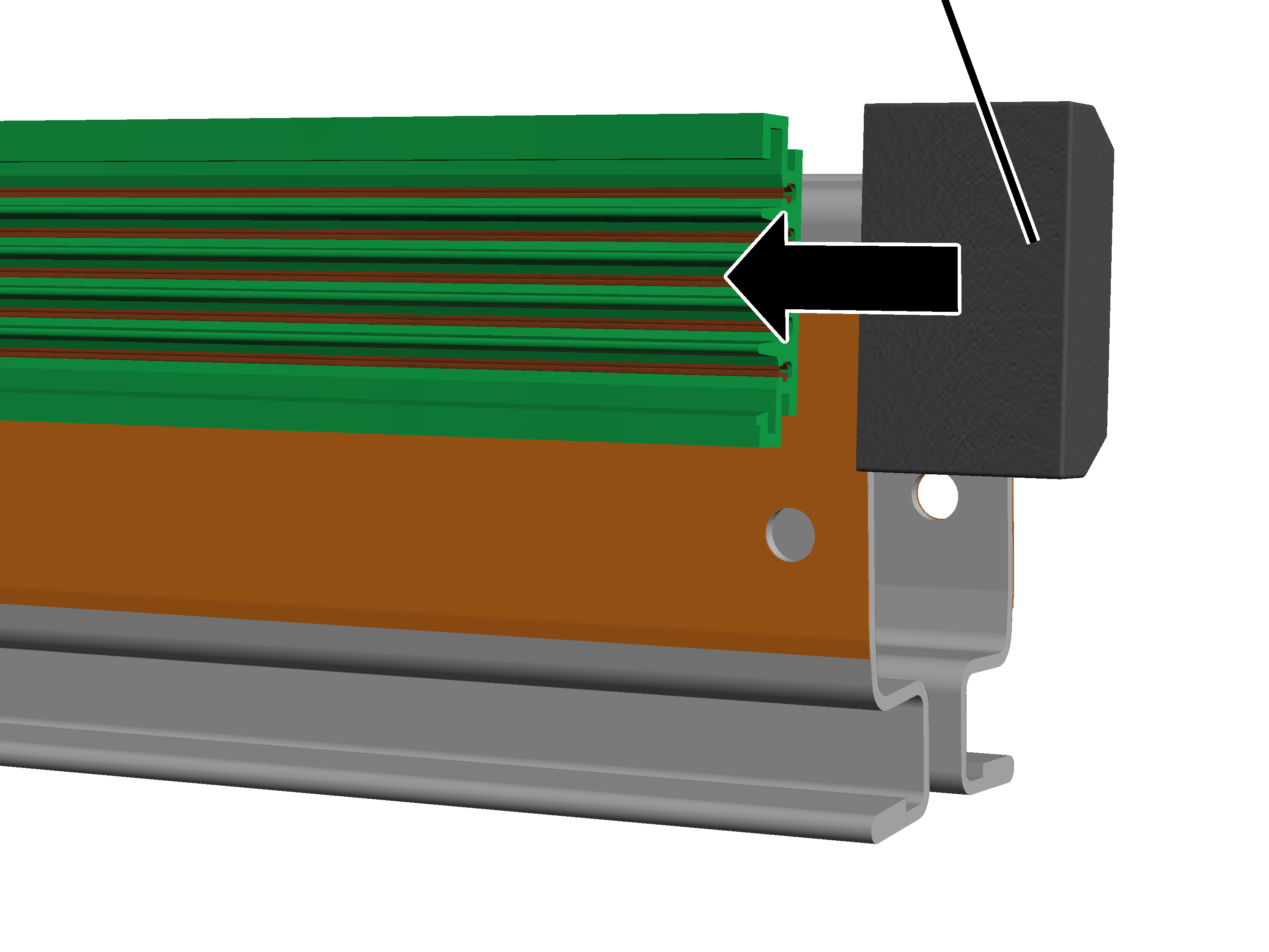
- Place the retaining cap on the conductor system.
- Securely bolt the retaining cap from the back side with self-drilling screws (2x).
Fitting the end caps on the HB profile rail
Every HB profile rail must be fitted with end caps on the profile ends. These prevent dirt from penetrating the HB profile rail and also serve as an end stopper to prevent the HB crane or trolley from falling out of the HB profile rail.
On the front and back of all HB profile rails:
End cap
- Push the spacer sleeve into the end cap.
Only with HB240: use the spacer sleeve with black coating. It is slightly longer than the spacer sleeve with silver or yellow coating.
- Put on the end cap.
If necessary, widen the HB profile rail slightly to enable insertion of the spacer sleeve.
Hexagon head screw
- Insert a hexagon head screw through the HB profile rail and the spacer sleeve.
Size |
Hexagon head screw |
|---|---|
HB110 |
M12x85 |
HB150 |
M12x110 |
HB190 |
M12x110 |
HB240 |
M12x110 |
- Insert washer, screw on the self-locking M12 nut and tighten to 80 Nm.
Installing the conductor system KBH
Additionally observe the supplied documentation of the conductor system KBH.
Preparing sections
- Lay out the individual sections of the conductor system on the floor as they will later be installed on the HB profile rail.
- Turn the sections so that the protective conductor marking (yellow-green line) points in the same direction at all points.
Only with HB 110, HB150 and HB190
Installing brackets on the HB profile rail
The conductor system KBH is installed on the profile head of the HB profile rail with fasteners.
On each support:
BracketRib screw M8x25
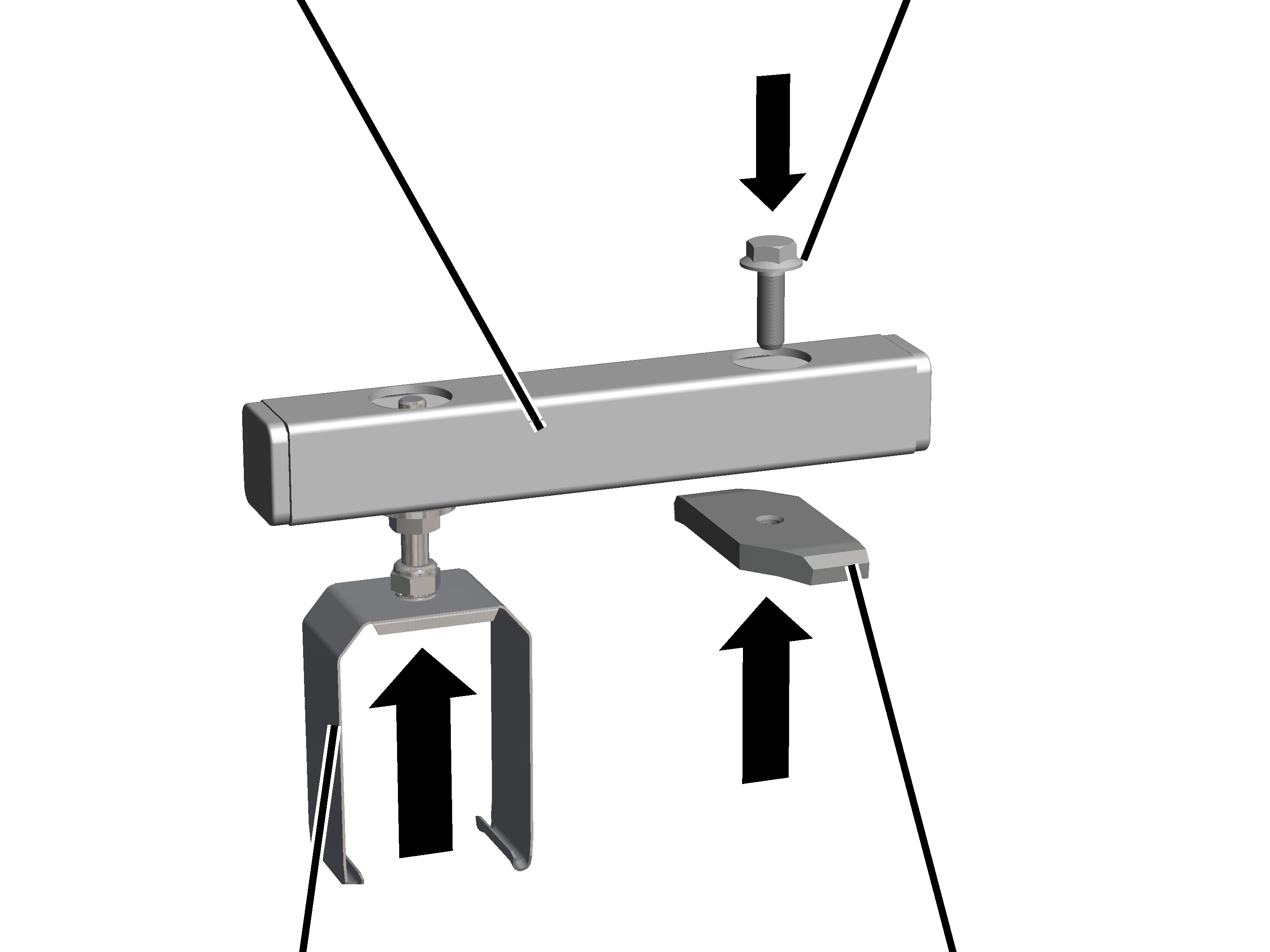
- Insert the suspension on one side of the support from below and bolt it tight.
- Insert an M8x25 rib screw on the other side of the support from above.
- Screw the head nut (2x) onto the rib screw from below.
Bracket
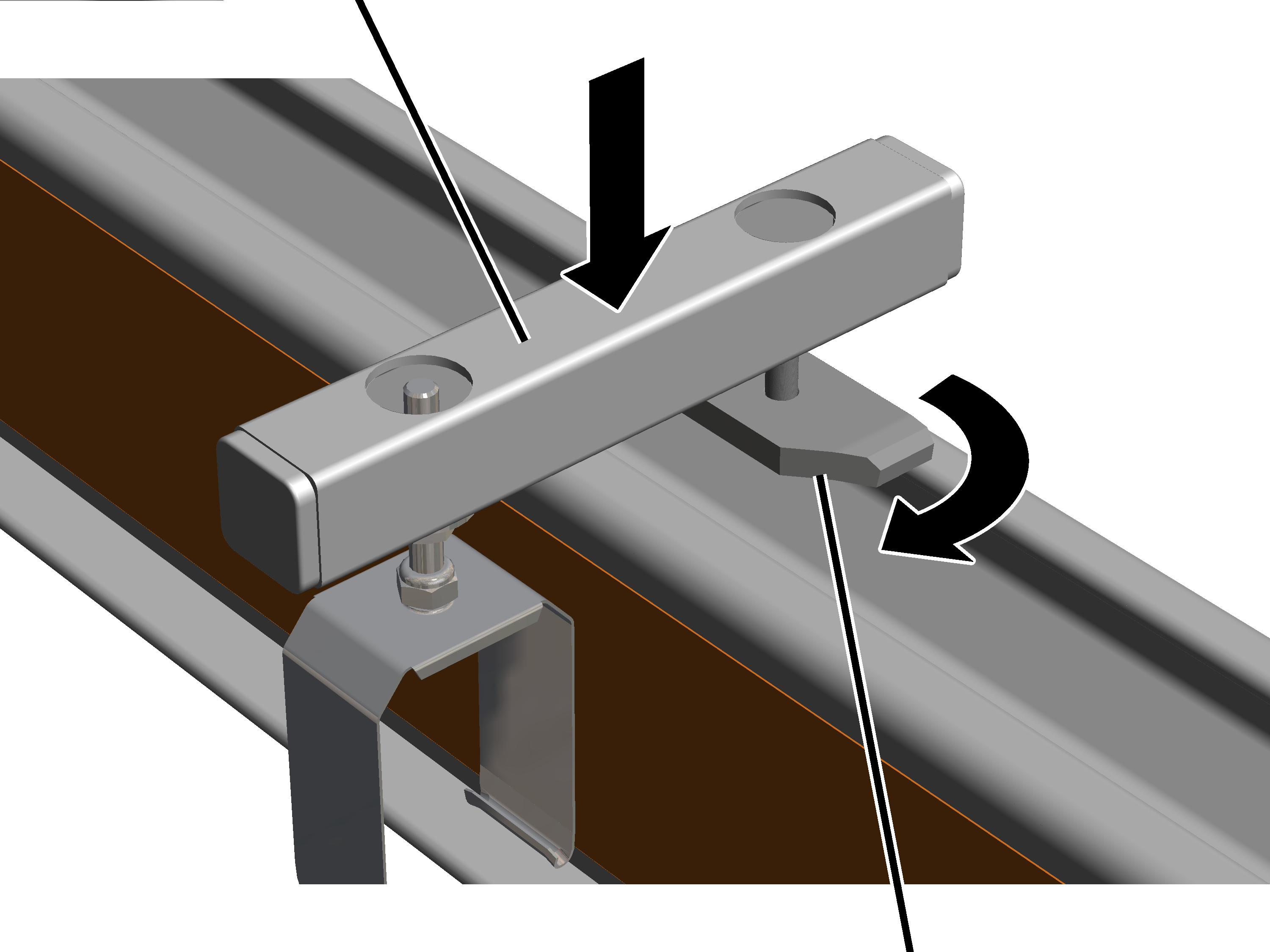
- Turn the head nut in the longitudinal direction and lay the support on the profile head from above.
- The head nut extends into the profile head.
- Screw the rib screw tight to 30 Nm.
- The head nut turns during fixing in the crosswise direction and is clamped tight in the profile head.
Installing sections
For every section:
Suspension
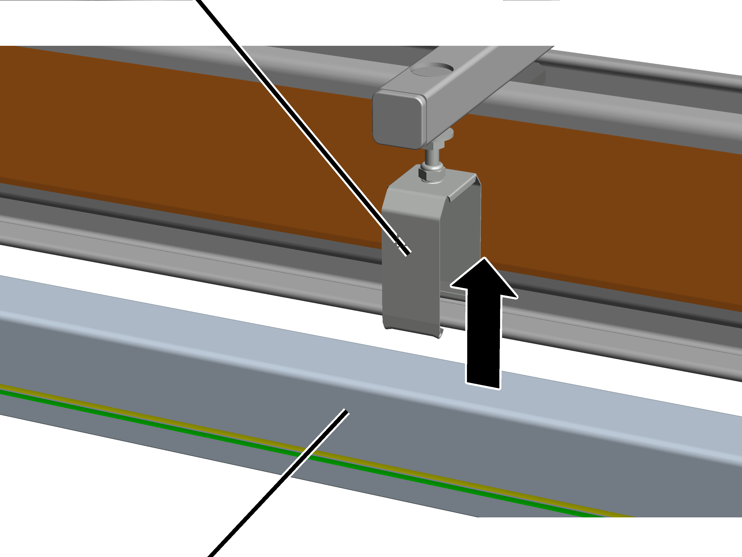
- Insert the section into the suspension from below.
- Hook the suspension with the hook into the conductor system from below.
- Check whether the section hangs in the suspension on both sides and can slide in the direction of the HB profile rail.
Only with HB240
Installing brackets on the HB profile rail
The conductor system KBH is installed on the profile head of the HB profile rail with fasteners.
On each support:
BracketRib screw M8x25
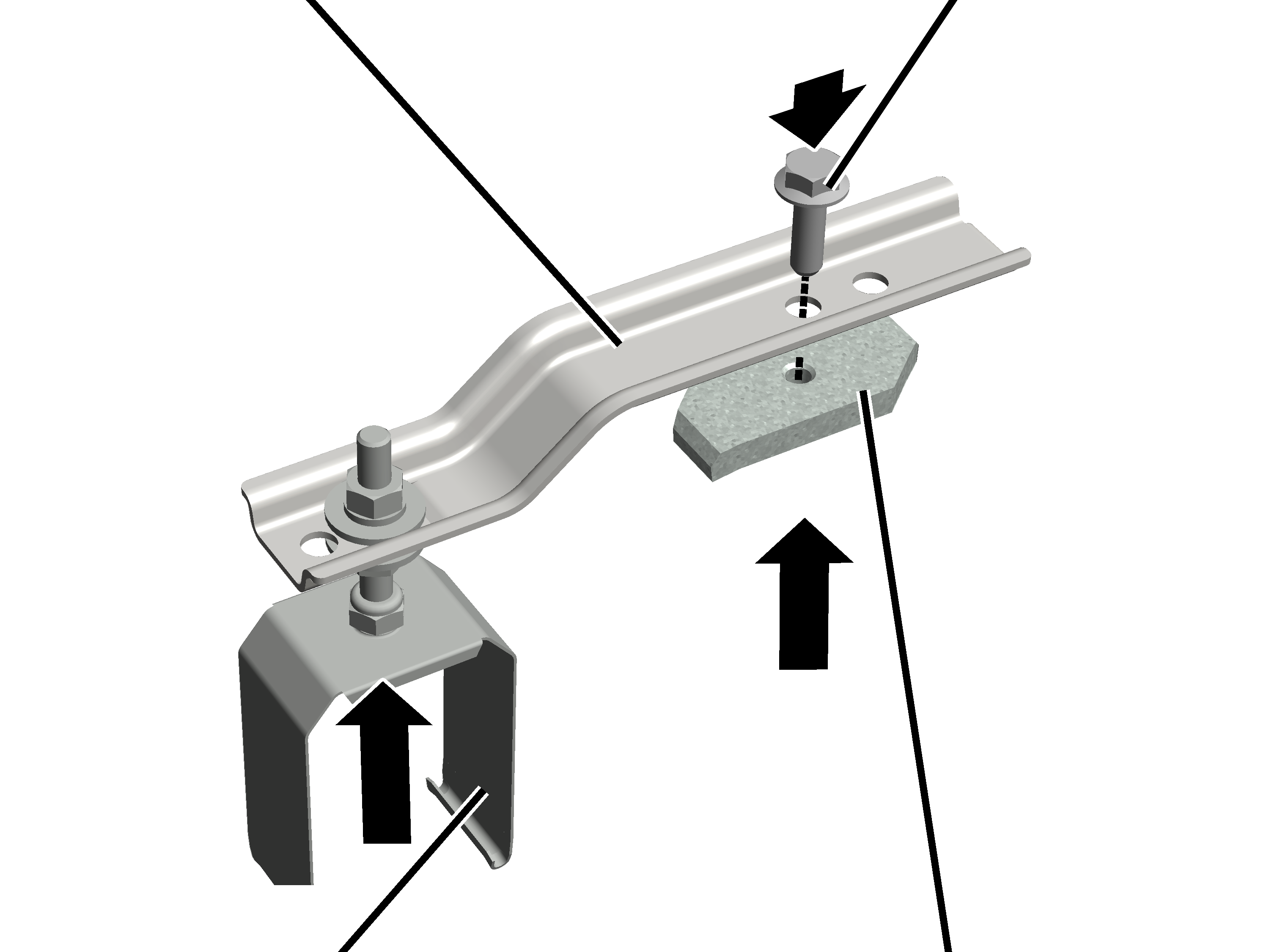
- Insert the suspension on the lowered side of the support from below into the inside hole and bolt it tight.
- Insert an M8x25 rib screw on the raised side of the support from above into the inside hole.
- Screw the head nut (2x) onto the rib screw from below.
Bracket
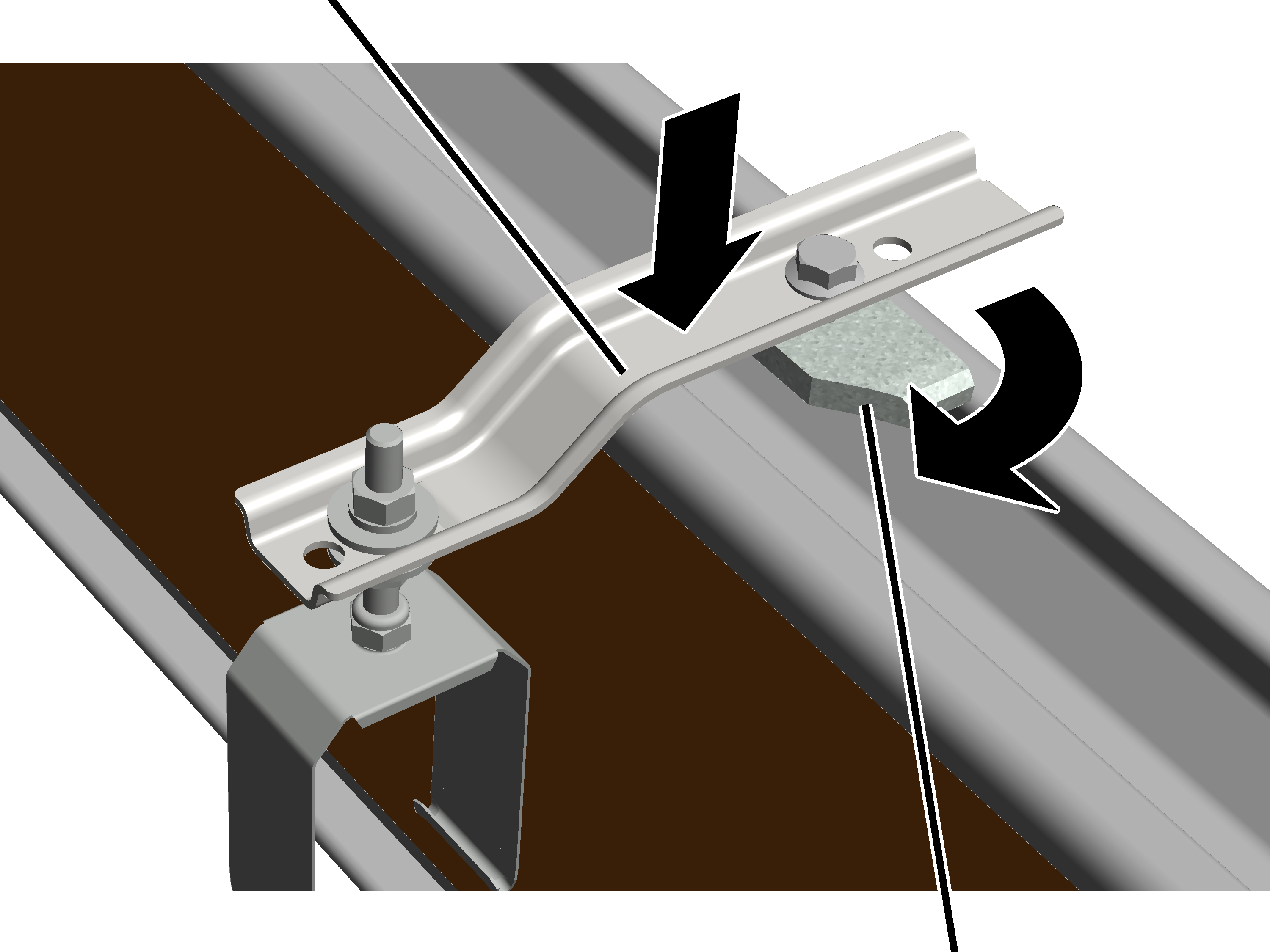
- Turn the head nut in the longitudinal direction and lay the support on the profile head from above.
- The head nut extends into the profile head.
- Screw the rib screw tight to 30 Nm.
- The head nut turns during fixing in the crosswise direction and is clamped tight in the profile head.
Installing sections
For every section:
Suspension
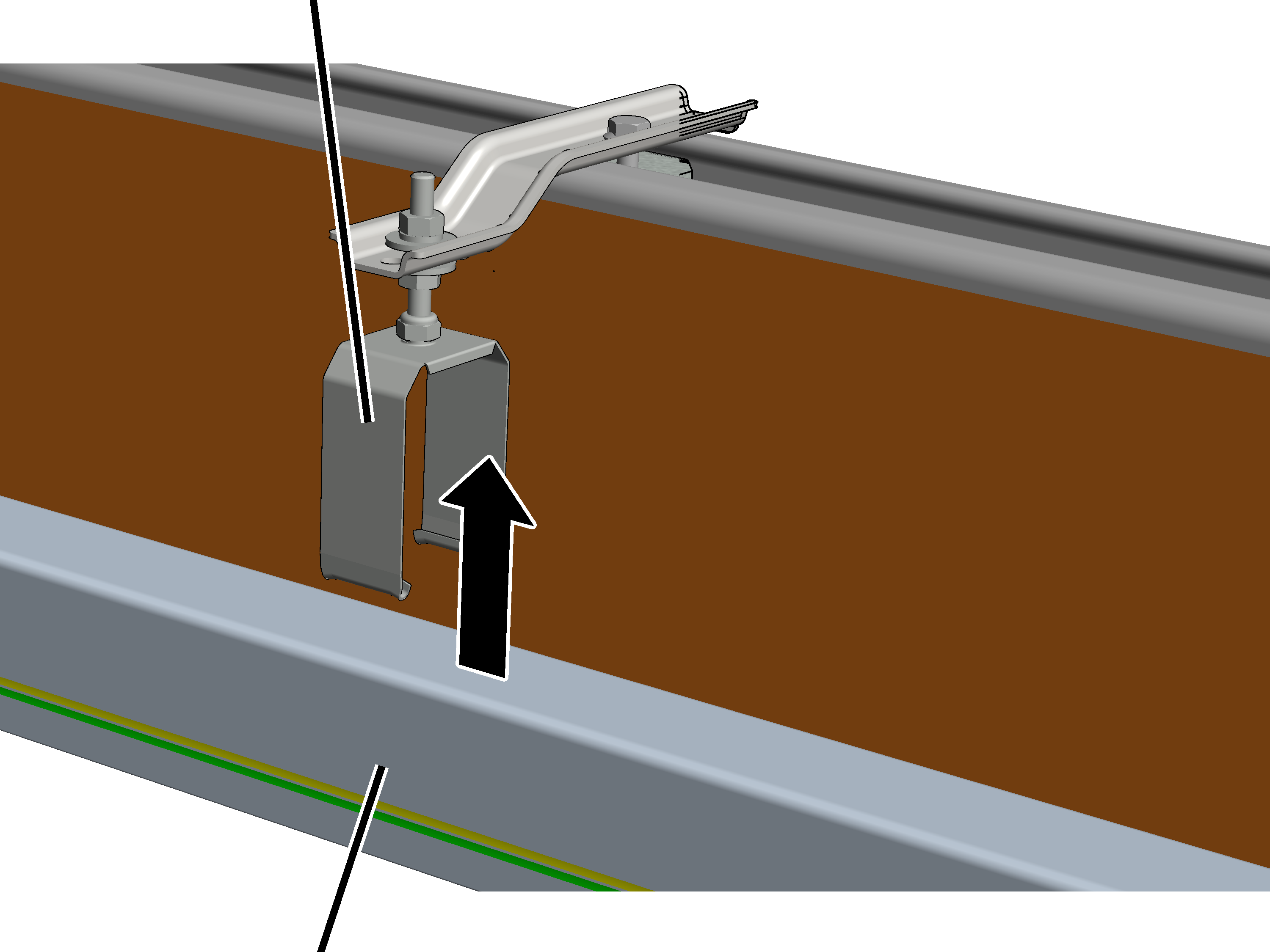
- Insert the section into the suspension from below.
- Hook the suspension with the hook into the conductor system from below.
- Check whether the section hangs in the suspension on both sides and can slide in the direction of the HB profile rail.
Connecting the sections electrically
The sections are electrically connected with one another by means of connectors.
At every joint:
Rail
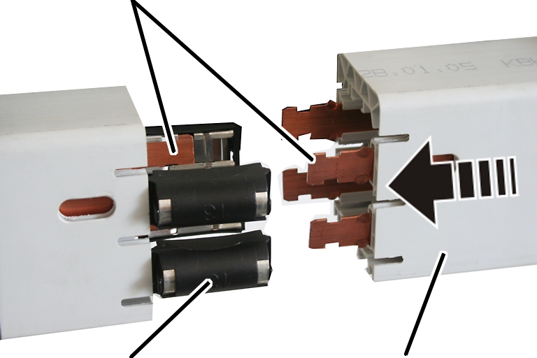
- On the right end of a section there is a connector inserted on every rail.
- On the left end of a section, the rails are shaped so that they cannot slip into the conductor system.
- Align the rails so that they can be inserted in the connectors.
- Place a wood block between the rails at the end of a section and use a hammer to strike the section against the previous one.
- The rail slides into the connector.
- Check all rails to ensure the connectors have securely latched.
Connecting the sections mechanically
A joint cover connects the sections with each other mechanically and protects against contact with the rails.
At every joint:
Joint cover
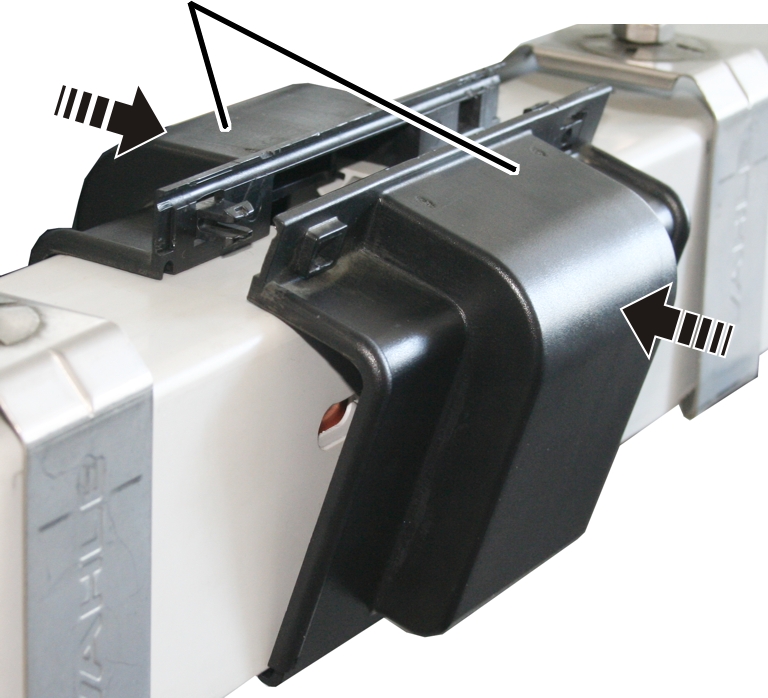
- Insert joint cover (2x) bottom in the conductor system.
- Press joint together at top and latch it.
Fixing a conductor system with fixed suspension
One of the sections is now fixed to the suspension. The other sections remain loosely latched. This allows the entire conductor system to freely expand or contract when temperatures change. However, due to the one fixed section, the entire conductor system cannot slide into the rest of the sliding suspension.
The section to be fixed should lie about in the middle (within the span of the conductor system).
Centred within the span of the conductor system:
Self-locking nut
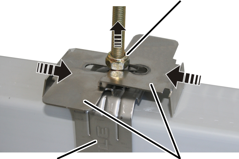
- Release the upper self-locking nut.
- Move the fixing clamps (2x) from the right and left between the self-locking nut and the suspension.
- Push the fixing clamps together so that they hook into each other.
Conductor system
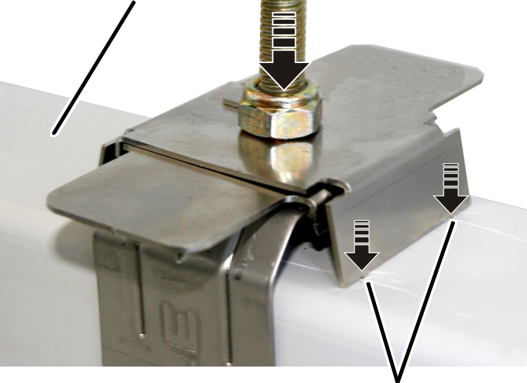
- Tighten the self-locking nut to 7 Nm.
- The fixing clamps fix the section by holding it in their claws.
- Check whether the conductor system can no longer slide.
Only with HB crane EHB and EHB-I
This section only applies if the KBH conductor system is mounted on the HB crane EHB or EHB-I. For all other HB cranes and on the HB crane runway, this section can be skipped over.
Installing counterweights
The counterweights ensure that the HB profile rails are suspended straight. Without the counterweights, the HB profile rails would sag on the side with the KBH conductor system.
On the opposite side of the conductor system:
Conductor system KBH
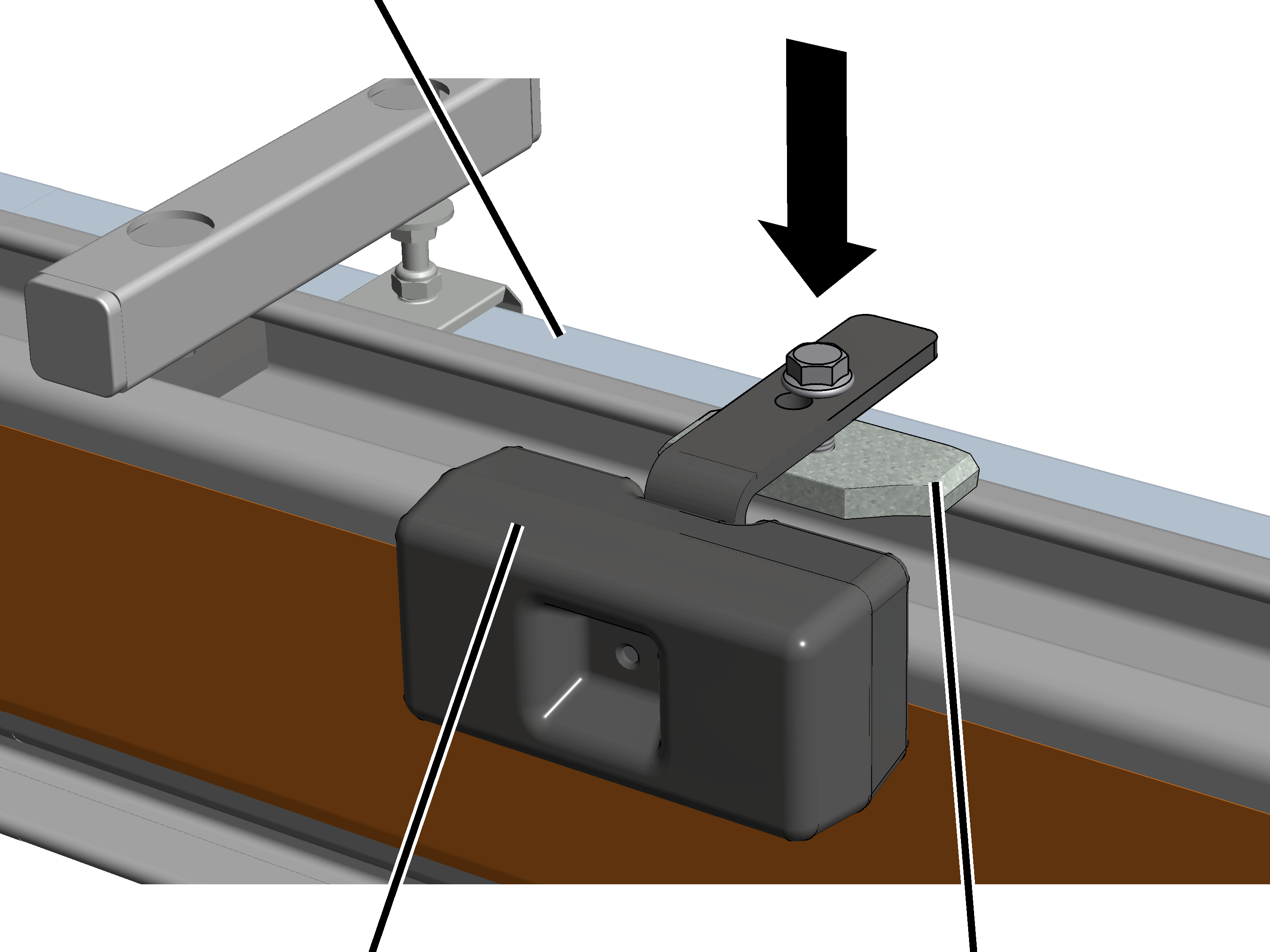
- Insert the counterweight in the profile head from above.
- Turn the head nut in the longitudinal direction.
- The head nut extends into the profile head.
- Tighten the rib screws to 30 Nm
- The head nut turns during fixing in the crosswise direction and is clamped tight in the profile head.
Inserting the current collector
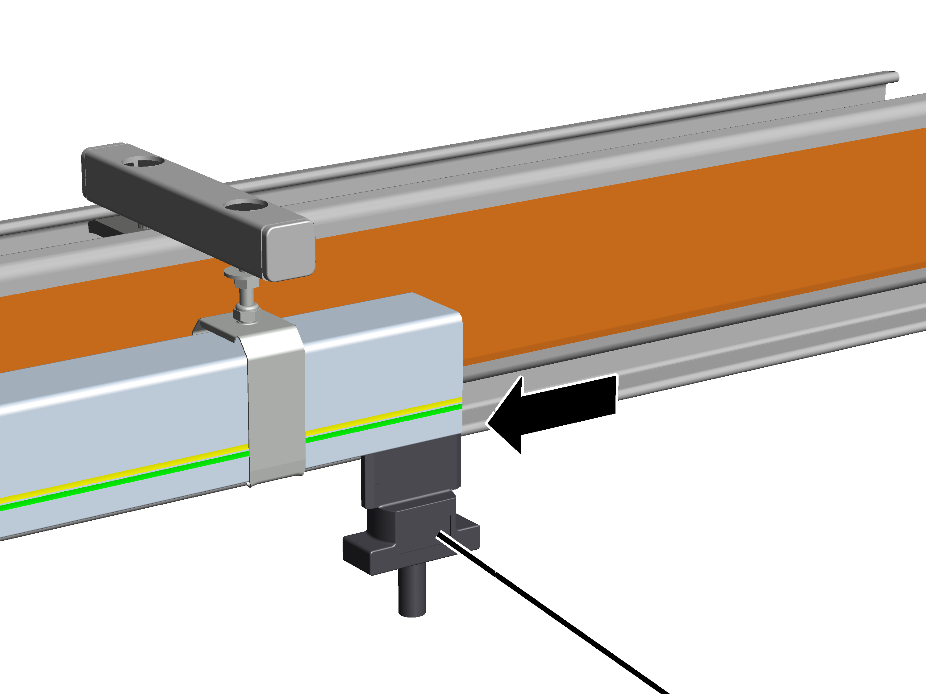
- Slide the current collector into the conductor system.
- Slide the current collector over the entire length of the conductor system to test it.
The current collector must move smoothly and not get caught, particularly at the joints.
Installing the power carrier
On the trolley:
The carrier shaft can also be installed in drilled holes on which other attached components (e.g. anti-collision device or HBF drive / travel drive) have already been installed. In this case, remove the installed bolt and mount the attached component with the carrier shaft.
Only with trolley with integrated anti-rotation device
This work step is only applicable if the trolley has a protruding nose next to the drilled hole as an integrated anti-rotation device.
Integrated anti-rotation device
- Push the carrier shaft directly into the drilled hole on the trolley.
Do not use the included separate anti-rotation device!
- The carrier shaft is secured on the trolley by means of an integrated anti-rotation device and cannot turn.
Only with trolley without integrated anti-rotation device
This work step is only applicable if the trolley does not have an integrated anti-rotation device.
Separate anti-rotation device
- Place the separate anti-rotation device over the drilled hole on the trolley.
- Push the carrier shaft through the separate anti-rotation device into the drilled hole on the trolley.
- The carrier shaft is secured on the trolley by means of the separate anti-rotation device and cannot turn.
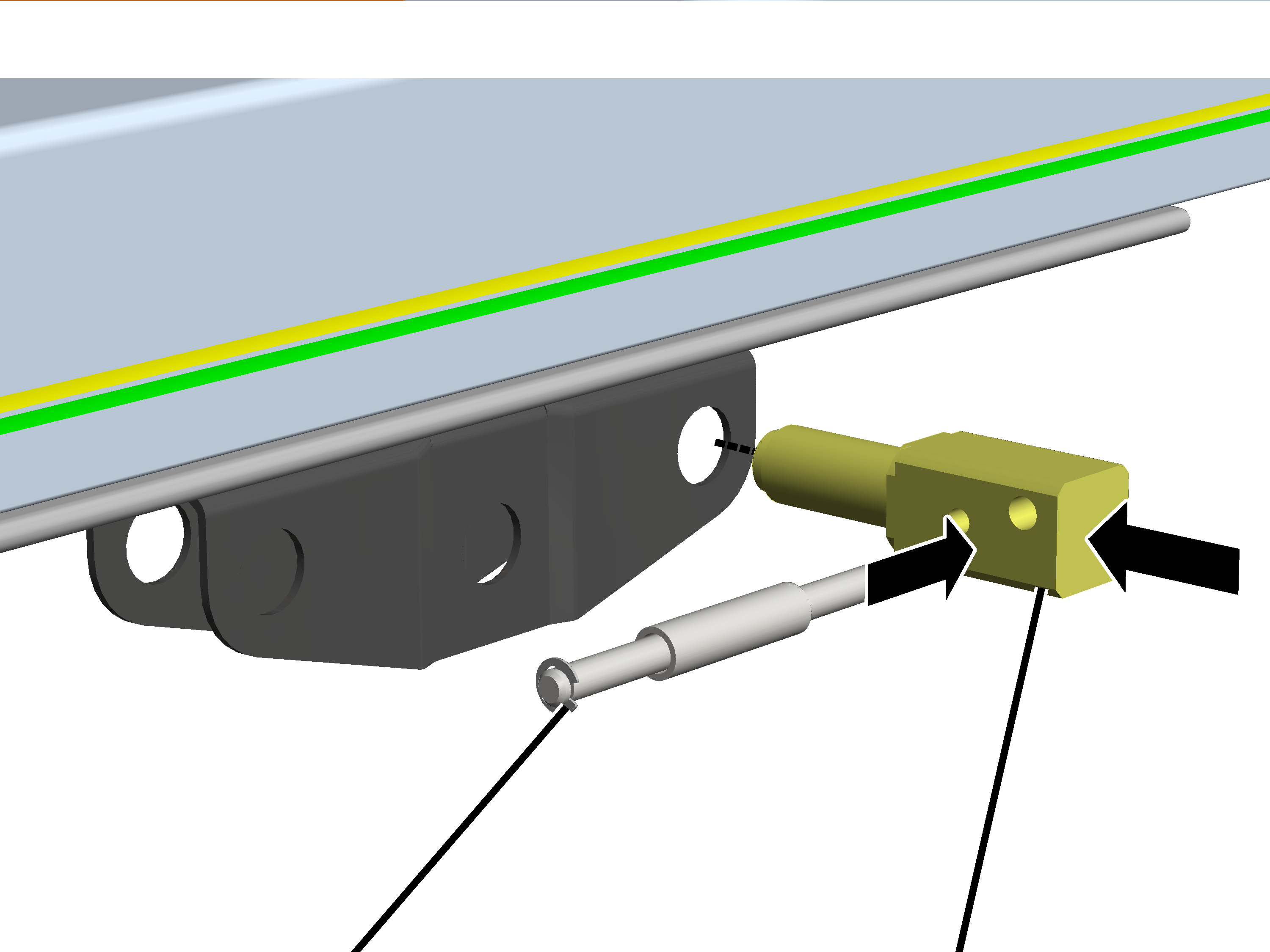
- Push the carrier shaft through the trolley.
How the carrier shaft is inserted (outer hole up or down) makes no difference.
- Insert the SL safety clip.
- Insert bolt with bush through the outer drilled hole in the carrier shaft.
Top tube on carrying forkCurrent collector
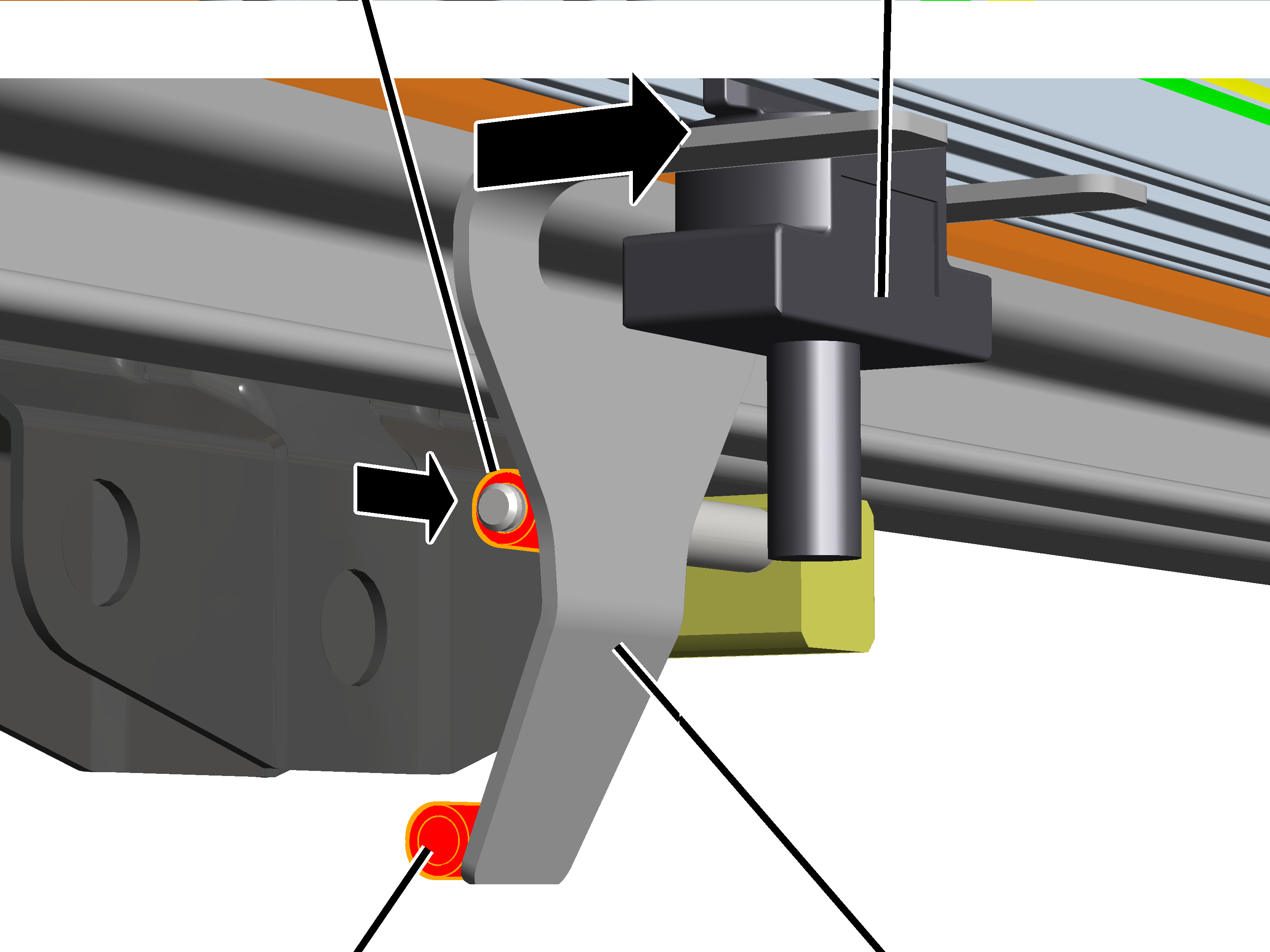
- Insert the carrying fork on the current collector.
- Push the carrying fork onto the bolt on the carrier shaft.
- For HB150 and HB190: use top tube on the carrying fork.
- For HB240: use lower tube on the carrying fork
- Secure bolt with SL safety clip.
Installing the feed unit
Cable fittingConductor system
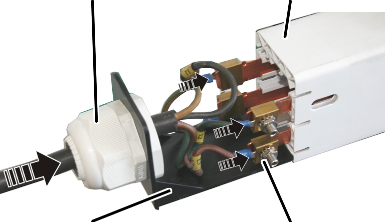
- Guide the connection cable through the cable fitting of the base plate.
- Attach the connection cable to the rail with the screw terminals.
- Push the base plate at the bottom into the conductor system.
If needed, the cable fitting can also be mounted so that it protrudes downward from the base plate. Depending on the particular fitting situation and spatial conditions on-site, this may enable improved guiding of the cable.
Retaining cap
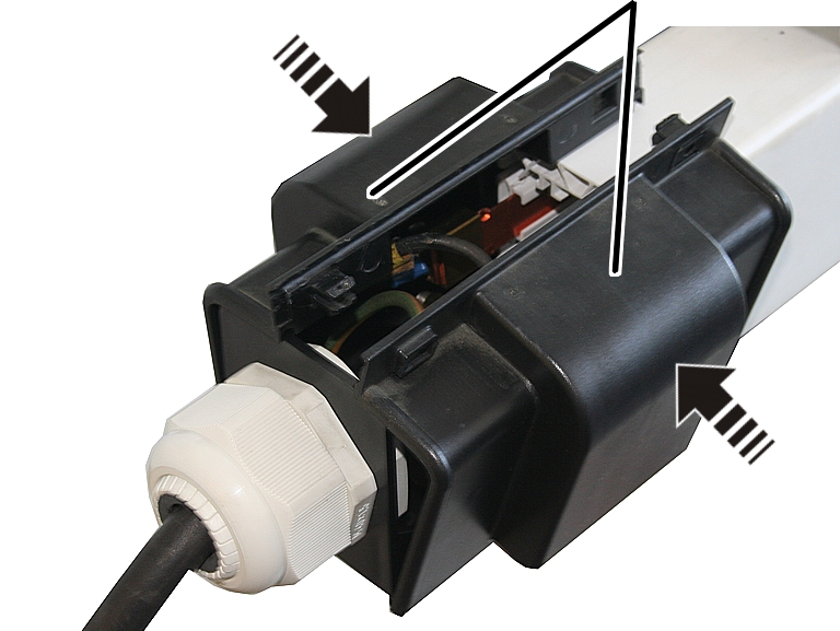
- Insert the retaining cap (2x) bottom in the conductor system and the base plate.
- Press the retaining cap together at the top and latch it.
Fitting the retaining caps on the conductor system
On the opposite end of the feed unit:
Retaining cap
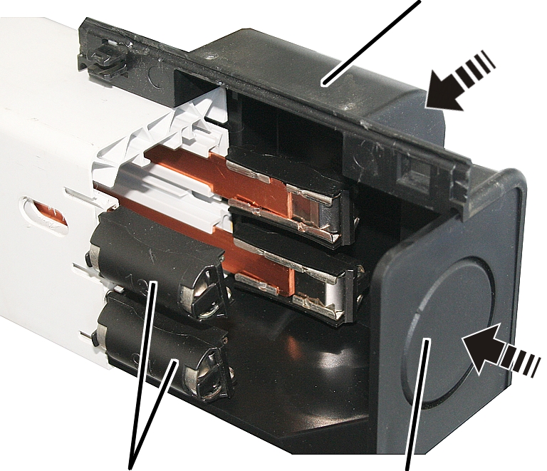
- Insert the base plate in the conductor system.
- Insert the retaining cap (2x) bottom in the conductor system and the base plate.
- Press the retaining cap together at the top and latch it.
- The rails and the connectors are protected against contact and dirt.
Fitting the end caps on the HB profile rail
Every HB profile rail must be fitted with end caps on the profile ends. These prevent dirt from penetrating the HB profile rail and also serve as an end stopper to prevent the HB crane or trolley from falling out of the HB profile rail.
On the front and back of all HB profile rails:
End cap
- Push the spacer sleeve into the end cap.
Only with HB240: use the spacer sleeve with black coating. It is slightly longer than the spacer sleeve with silver or yellow coating.
- Put on the end cap.
If necessary, widen the HB profile rail slightly to enable insertion of the spacer sleeve.
Hexagon head screw
- Insert a hexagon head screw through the HB profile rail and the spacer sleeve.
Size |
Hexagon head screw |
|---|---|
HB110 |
M12x85 |
HB150 |
M12x110 |
HB190 |
M12x110 |
HB240 |
M12x110 |
- Insert washer, screw on the self-locking M12 nut and tighten to 80 Nm.
Connecting the mains power supply
Only with festoon cable system and conductor system VKL
RiserCable bushing
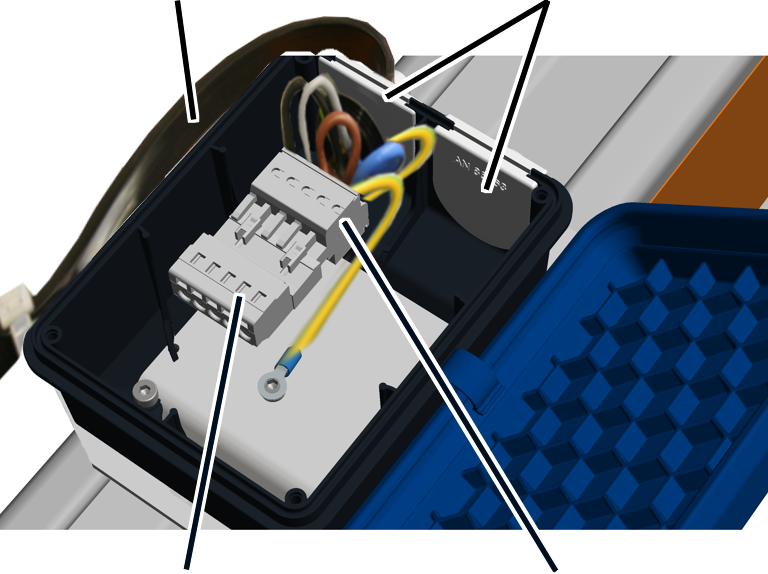
Connecting supply line (from the riser):
- Guide the riser through the cable bushing into the connector housing.
- Connect the riser (voltage carrying) to the bush multipoint connector. See the wiring diagram.
- Screw the protective conductor with the cable lug onto the base plate.
- Connect the protective conductor from the base plate to the bush multipoint connector (two rows).
Connecting the outlet (to the mains power supply):
- For festoon cable system as mains power supply: guide the festoon cable system of the mains power supply through the cable bushing into the connector housing and connect it to the pin multipoint connector.
- For conductor system VKL as mains power supply: guide the connection cable to the feed unit through the cable bushing into the connector housing and connect it to the pin multipoint connector.
Only with conductor system KBH
Cable fittingConductor system
- Guide the riser directly through the cable fitting of the base plate and connect it.
See also “Installing the feed unit”.
Inspection
This section applies to anyone who inspects and accepts the crane in accordance with occupational health and safety requirements
The HB system must be regularly inspected in order to guarantee safe operation. The end user is responsible for this regular inspection.
At the start
Test intervals
The regular inspection is performed at least once annually.
Under certain conditions, more frequent regular inspections may be necessary. Reasons include:
- Frequent operation at the load capacity
- Working in multiple shifts
- Frequent use
- Dusty or chemically aggressive environment
The end user is responsible for checking the requirements and determining the test intervals. ABUS will gladly assist you if questions arise.
Requirements for the examiner
The end user of the crane is responsible for the proper qualifications of the examiner.
Examples of qualified persons:
- Persons with comprehensive knowledge from specialist training in engineering and in the electrical systems of cranes.
- Persons with sufficient experience in the operation, installation and maintenance of cranes.
- Persons with comprehensive knowledge regarding the relevant technical rules, directives and safety regulations applicable in the respective country.
- Persons receiving regular training from ABUS.
Scope of the test
The qualified person inspecting the HB system is responsible for the type and scope of the inspection.
Overview: inspecting the HB system
In addition to the points described here, all points outlined in the other supplied product manuals must also be checked.
The decision as to whether the HB system is in a perfect condition may only be made by the examiner. Any inadequacies, if found, must be eliminated. The examiner decides whether the HB system will then need to be inspected again.
If locally applicable regulations specify further tests, these are likewise to be carried out.
Additionally, at least the following points must be checked:
- Check HB profile rails on HB crane runway and on the crane girder (visual inspection). No cracks or similar damage may be visible.
- Inspect bolts and SL safety clips. See “Inspecting bolts and SL safety clips”.
- Inspect trolleys. See “Inspecting trolleys”.
- Check cross bar HB10/HB11. See “Check cross bar HB10/HB11”.
- Inspect the HBF drive. See “Inspecting HBF drives”.
- Only for HBF drive: inspect reference gap, brake lining thickness and O-rings. See “Inspecting the brake on the drive”.
- Inspect end caps. See “Inspecting end caps”.
- Inspect craneway suspensions. See “Inspecting craneway suspensions”.
- Inspect rubber mounting. See “Inspecting the rubber mounting”.
- Inspect profile joints. See “Inspecting profile joints”.
- Inspect conductor system. See “Inspecting the conductor system”.
- With EHB-X and ZHB-X: check screws on head. See “Checking the screws on the head”.
Inspecting bolts and SL safety clips
For all bolts and SL safety clips:
- All bolts and SL safety clips must be present.
- All SL safety clips must be properly inserted and secured.
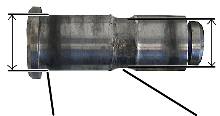
- Measure the diameter at multiple points. The bolt may be abraded by a maximum of 2 mm at the thinnest point.
Drilled hole in steel part
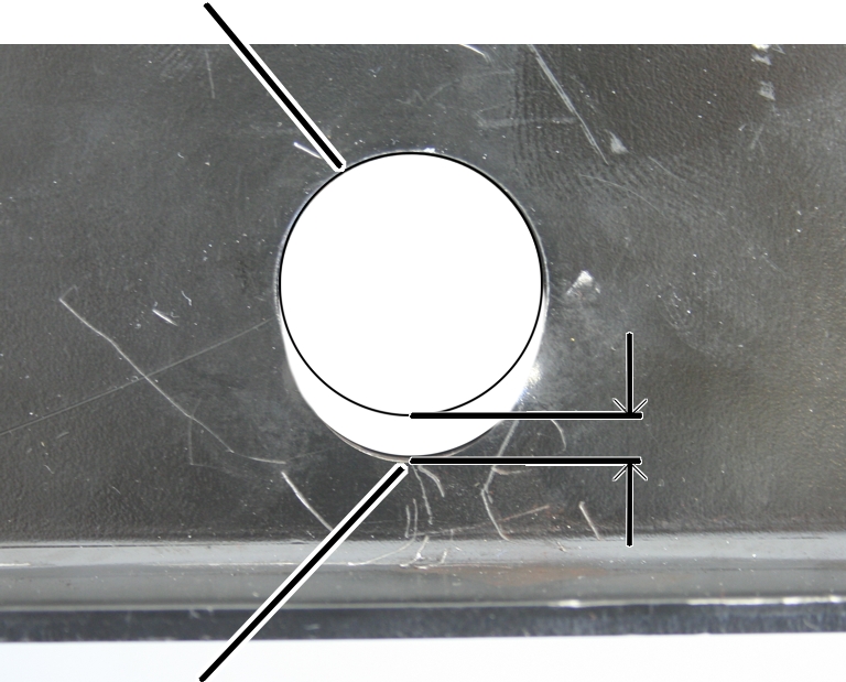
- Measure holes in the fixed parts at multiple points. The holes may be maximally abraded by 2 mm.
- If bolts or SL safety clips are missing, damaged, or more heavily worn than permitted: replace bolt and SL safety clip.
Inspecting trolleys
On all trolleys:
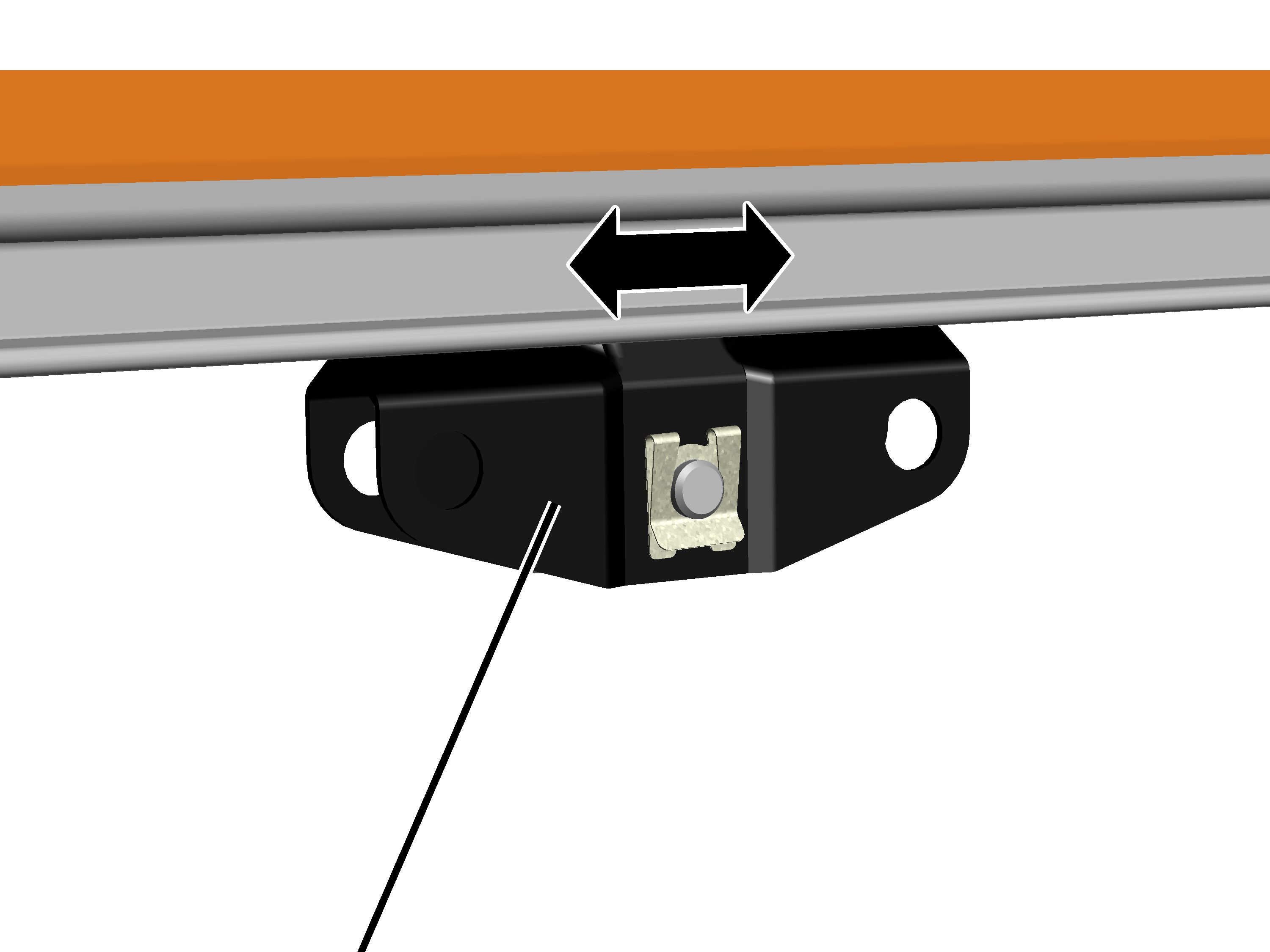
- Move all trolleys back and forth individually.
- The trolleys must run smoothly and uniformly. No rhythmic noises should be audible.
- If a trolley is not running evenly or you hear rhythmic noises: replace the trolley. See "Replacing a trolley".
Check cross bar HB10/HB11
On the cross bars HB10/HB11:
Ball bushing
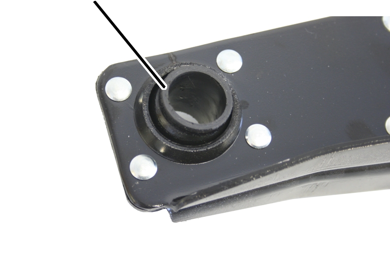
- Remove bolt and SL safety clip.
- Inspect ball bushings.
The ball bushings may not be damaged and should rotate freely in all directions.
- If one of the ball bushings is damaged: remove the cross bar HB10/HB11 and install a new cross bar HB10/HB11.
Inspecting HBF drives
Checking the pre-tension of the plate springs
On all HBF drives:
Plate springs
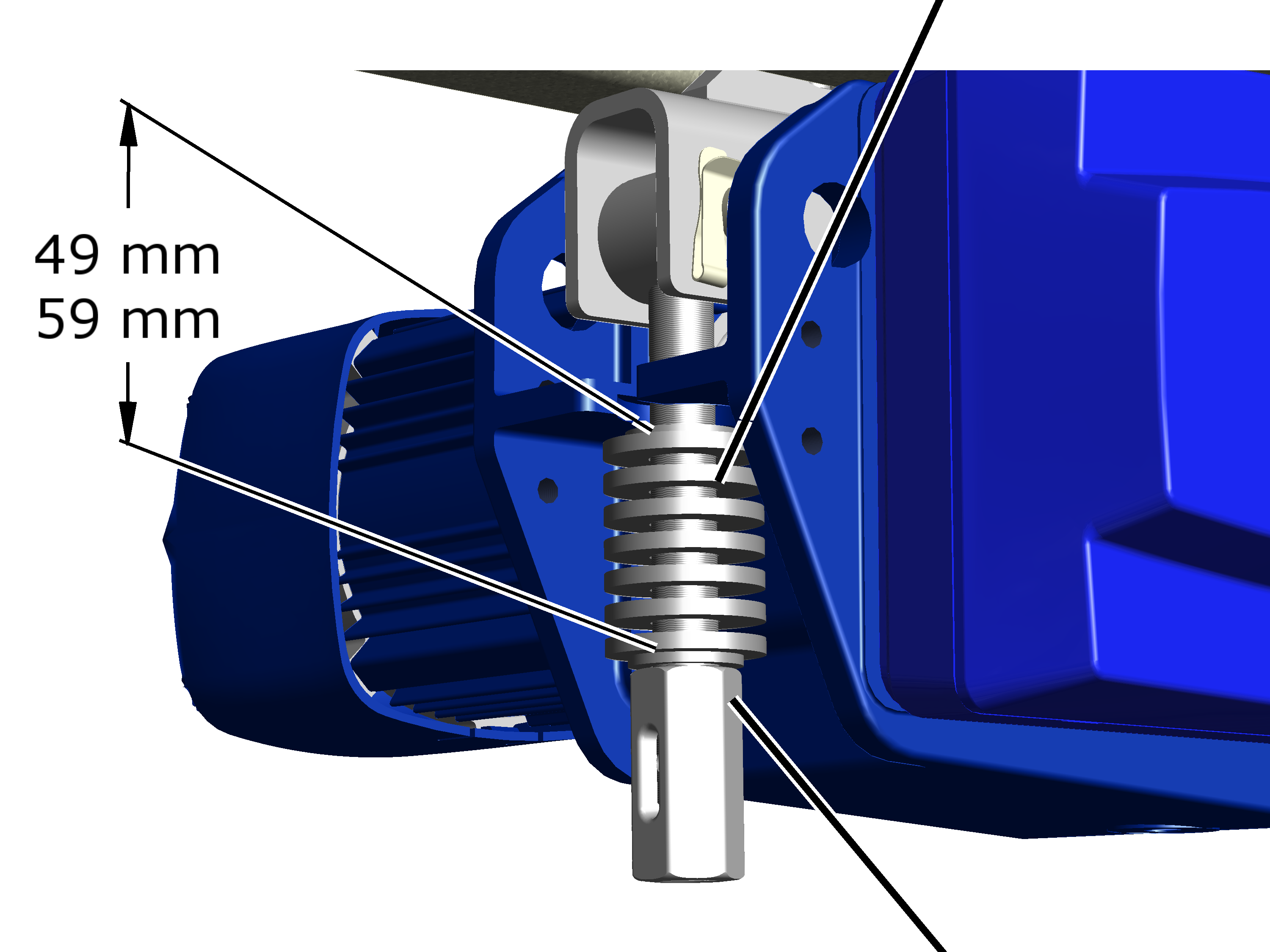
- Check the pre-tension of the plate springs. The coupling must be turned far enough so that the plate springs (including the upper and lower discs) are the right length:
- For connection of the HBF drive on the friction wheel side: H = 59 mm.
- For connection of the HBF drive on the travel motor side: H = 49 mm.
- If the plate springs are tensioned too much or too little: readjust them.
Inspecting the friction wheel
On all HBF drives:
Heavily damaged area on the friction wheel
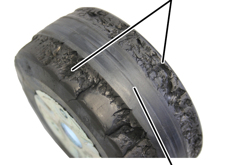
- Inspect the running surface of the friction wheel. The running surface may not be cracked, heavily worn or otherwise damaged.
- If the running surface of the friction wheel is no longer in good condition: replace the friction wheel. See “Changing the friction wheel”.
Inspecting the brake on the drive
To check the brake, the reference gap between the brake bearing shield and anchor plate is measured, as well as the brake lining thickness.
A step (for the O-ring) makes the air gap (distance between brake bearing shield and anchor plate) difficult to access. Therefore a reference gap is measured outside on the motor in order to obtain information on the width of the air gap.
Overview:
Brake lining thicknessReference gap (between brake bearing shield and anchor plate)
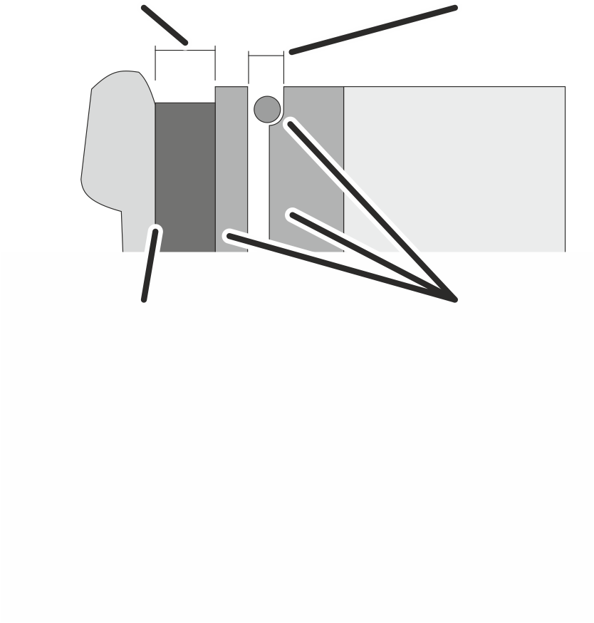
Dimension |
Value |
|---|---|
Reference gap between anchor plate and brake bearing shield |
Between 3.1 mm and 3.7 mm |
Brake lining thickness |
At least 2 mm |
Brake lining thickness |
New: 4 mm |
If the reference gap is wider than permitted, the brake must be readjusted. If the minimum brake lining thickness is reached, the fan blade with brake lining must be replaced.
If the width of the reference gap is within the permitted range but usage behaviour leads to the expectation that the reference gap will be wider than permitted before the next regular inspection, the fan blade with brake lining must be replaced now.
Taking off the fan cover
- Take off the fan cover.
Measuring the reference gap
- Measure the distance between brake bearing shield and anchor plate.
- If the reference gap is larger than 3.7 mm: Adjust the brake. See “Setting the air gap on the brake”.
Measuring brake lining thickness
- Check the thickness of the brake lining with a calliper.
- If the brake lining is less than 2 mm thick: replace the fan blade with brake lining. See “Replacing the fan blade with brake lining and anchor plate”.
Checking the O-ring
The area between the brake bearing shield and the anchor plate (reference gap) is protected from dust by an O-ring. The O-ring must not become damaged or missing.
Anchor plateBrake bearing shield
- Check the O-ring (between brake bearing shield and anchor plate).
The O-ring must not be torn, dented or damaged in any other way, nor be missing completely.
- If the O-ring is damaged or missing, fit a new O-ring. See “Replacing the O-ring, plate springs, compression springs and feather key”.
Closing the fan cover
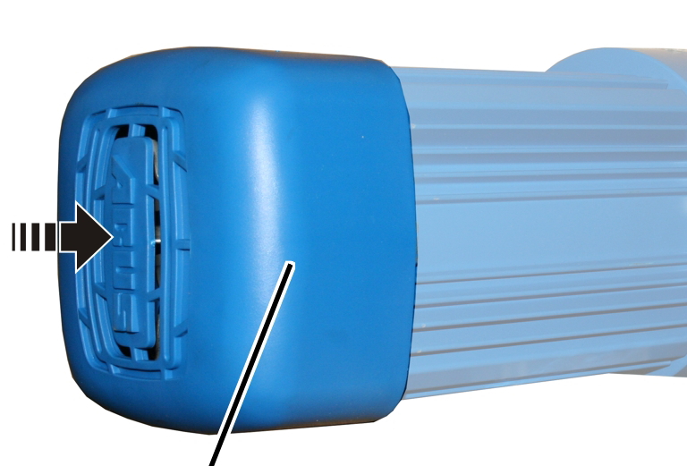
- Attach fan cover.
Inspecting end caps
On all end caps on the crane track and on the crane girder:
Hexagon head screw M12x110End cap
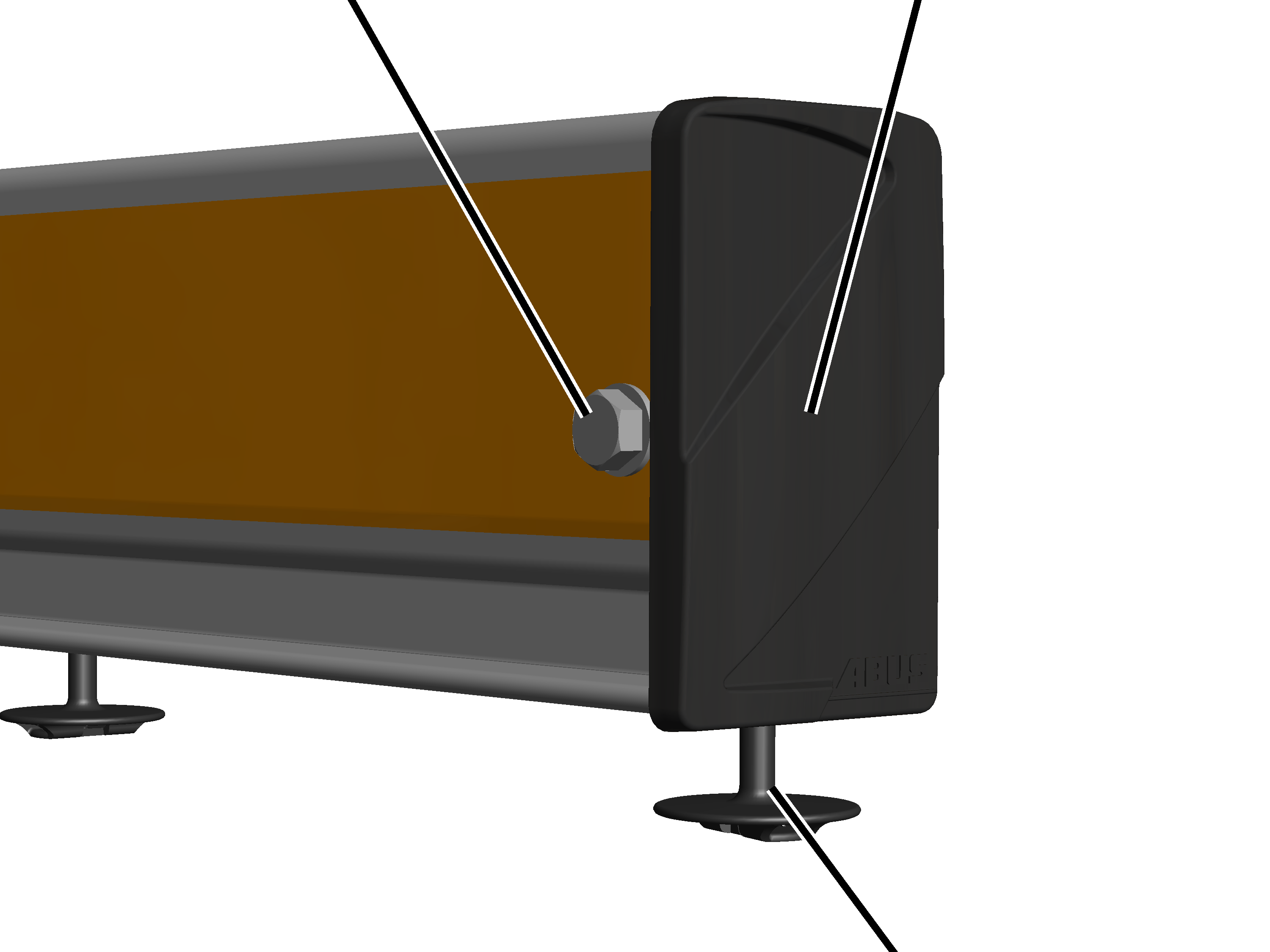
- Inspect end caps. They should not be broken or otherwise damaged.
- With festoon cable system: check cable slider on profile end. It must rest firmly in the end cap and should not slide.
- Check the M12x110 hexagon head screw in the end cap. It must be present and free of any heavy deformation.
- If the end cap, cable slider or hexagon head screw are damaged: replace the respective part.
Inspecting craneway suspensions
Inspecting ceiling-mounted brackets
On all craneway suspensions:
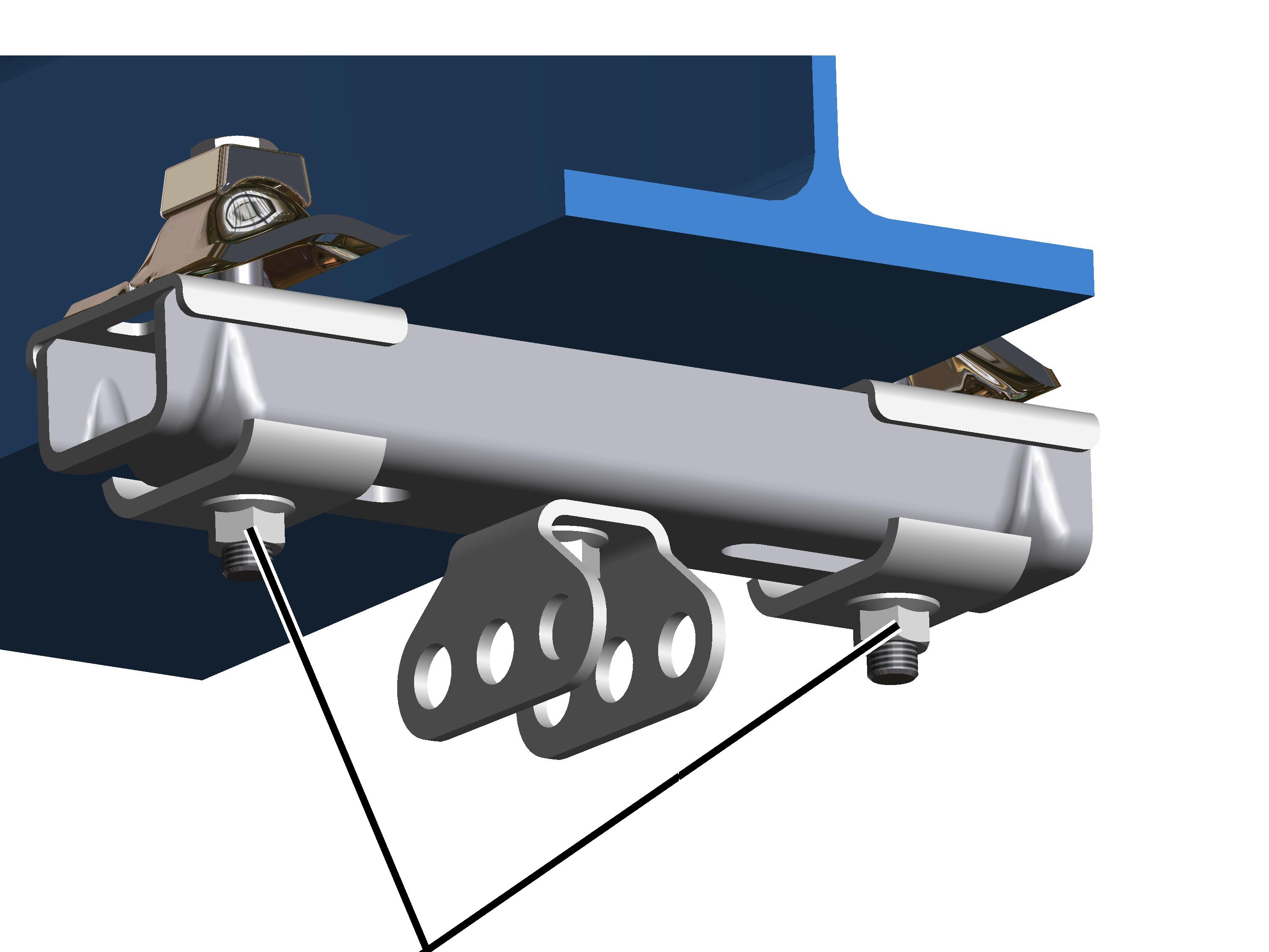
- Inspect the rib screws or rib nuts on the ceiling-mounted bracket. They must be tightened with the correct torque.
- If the ceiling-mounted brackets are not properly tightened: tighten the rib screws or rib nuts to the correct torque.
Inspecting spring cotters
On all craneway suspensions:
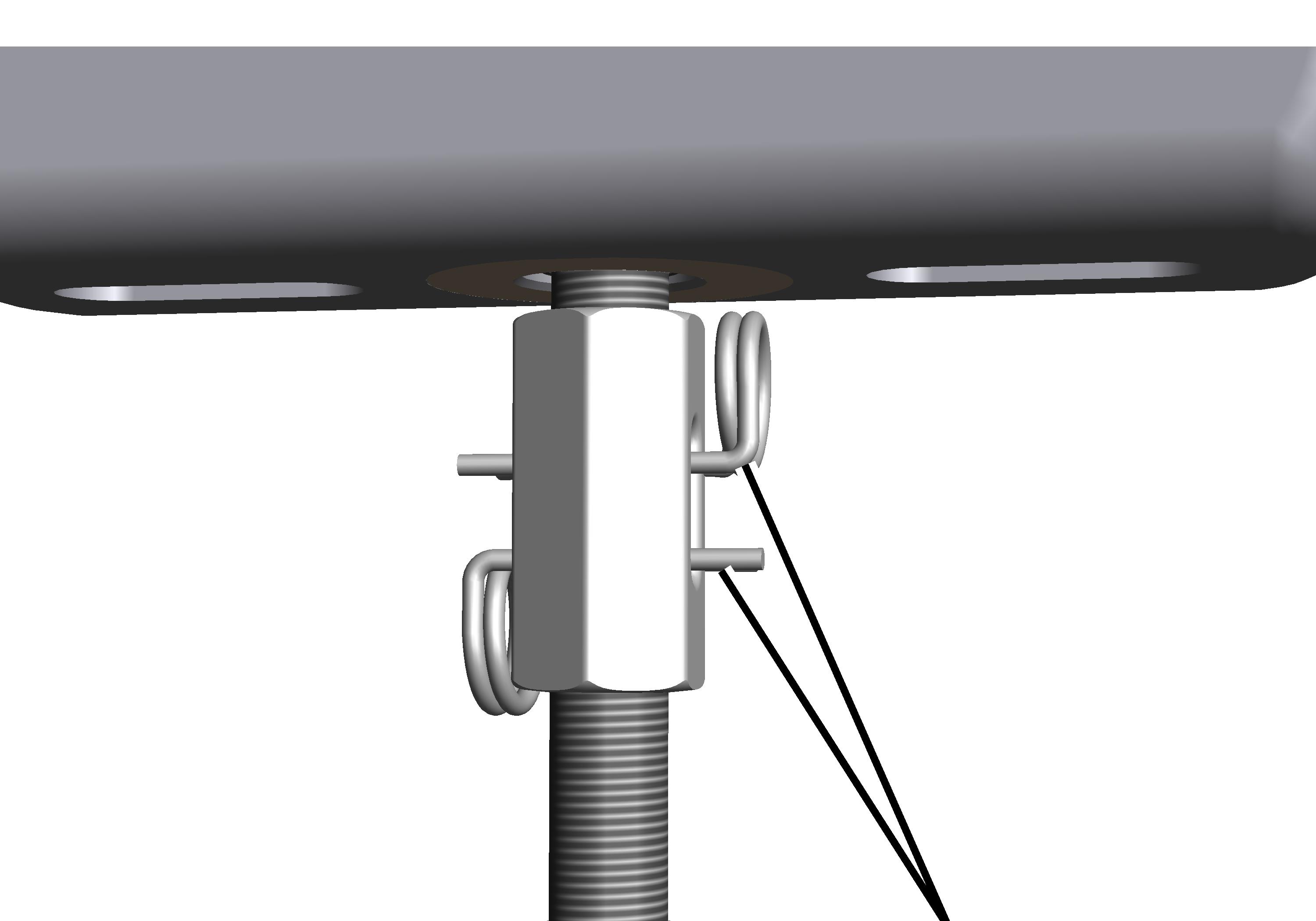
- Inspect the spring cotters. They must be present and fully inserted.
- If a spring cotter is missing: insert a new spring cotter.
- If a spring cotter is not correctly inserted: fully insert the spring cotter.
Inspecting the rubber mounting
The craneway suspensions and crane girder suspensions are wear-free parts.
Nevertheless, the rubber mountings must be checked at the regular inspection for material changes and deformations which may have occurred due to, for example, excessive or impermissible loads.
The condition of the rubber mountings is evaluated based on rolled-out rubber threads and rubber bulges and compared with the following images. The rubber mountings in the profile connections can be checked in the installed state.
Only with head EHB-X and ZHB-X as well as on the cross bar HB22
Profile link
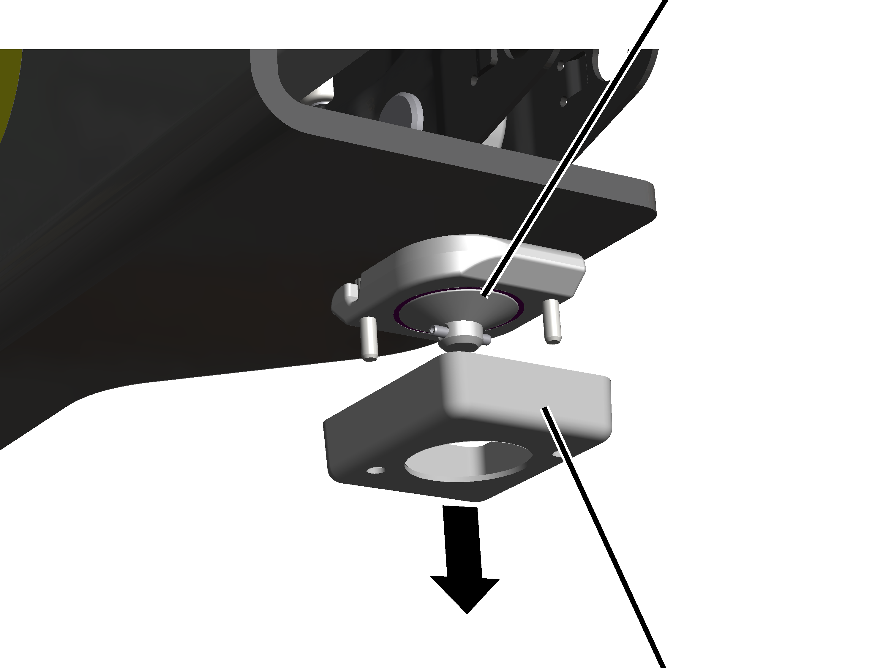
- Screw the cap off.
- The profile link is visible and can be examined.
- Inspect the profile link on the underside. See “Checking the underside of the profile connection”.
The top side of the profile link does not need to be inspected.
Checking the top side of the profile connection
On all ceiling-mounted brackets and crane girder suspensions:
- Check the condition of the rubber mounting in the profile connection on the top side and compare it with the following images.
Example showing an "as new" profile connection:
"As new" rubber mounting
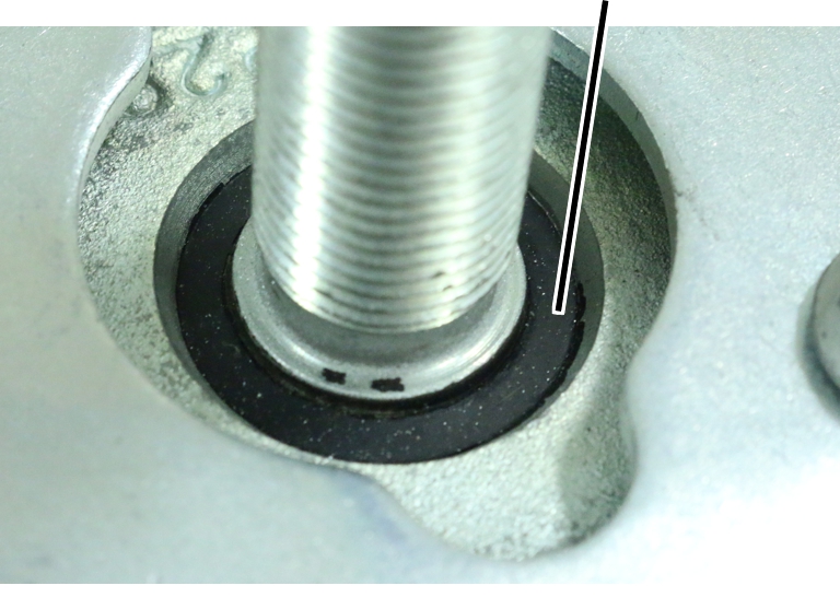
- No rolled-out rubber threads are visible.
- There may be a thin ridge or a thin film visible on the edge of the rubber mounting.
Example of a profile connection with still acceptable rolled-out rubber bulges:
Rolled-out rubber bulges
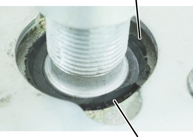
- The filling of the rubber mounting flattens out upwardly out of the profile connection.
- Rolled-out rubber threads or small rubber bulges are visible.
Example of a profile connection with too heavily rolled-out rubber threads, which must must be replaced:
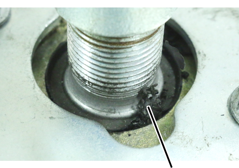
- An increasing number of ever longer rubber threads roll out upwardly from the profile connection.
- The rubber threads can emerge on one side or all around the circumference of the rubber mounting.
Checking the underside of the profile connection
If initial rolled out rubber threads are visible on the top side:
The movements within the rubber mounting are equally strong on the top side and underside. If initial rolled out rubber threads are visible on the top side, the underside of the rubber mounting must also be checked.
Options for performing the examination:
- Feel along the underside of the profile connection for rubber bulges or rolled-out rubber threads.
- Examine the underside of the profile connection with a mirror or camera.
- Unscrew the retaining cap, release the tension nut and remove the profile connection.
- Check the condition of the rubber mounting in the profile connection on the underside and compare it with the following images.
Example showing an "as new" profile connection:
"As new" rubber mounting
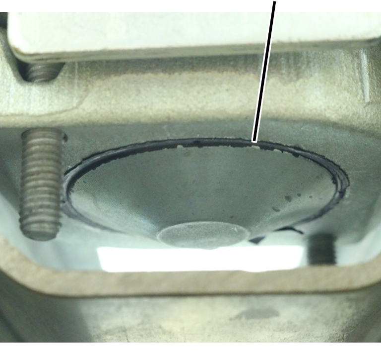
Example of a profile connection with still acceptable rolled-out rubber threads:
Rolled-out rubber threads
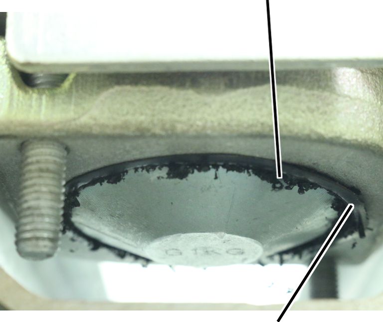
Example of a profile connection with too heavily rolled-out rubber threads, which must must be replaced:
Clearly visible, long, rolled-out rubber threads
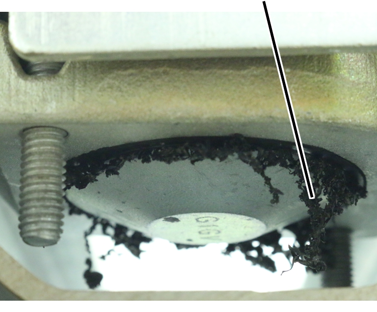
Replacing the profile connection
If the condition of the top side or underside is similar to the condition depicted with too heavily rolled-out rubber threads or rubber bulges:
- Remove the profile connection and replace it with a new one.
- Likewise remove the ceiling-mounted bracket and install a new one.
Profile connection and ceiling-mounted bracket must always be replaced in pairs.
The bearing shell in the ceiling-mounted bracket and in the profile connection must always have the same colouring (silver or yellowish). Ceiling-mounted brackets and profile connections with differently coloured bearing shells must not be installed together.
Inspecting profile joints
Inspecting profile joints
On all profile joints on the crane track and on the crane girder:
Cup square bolt
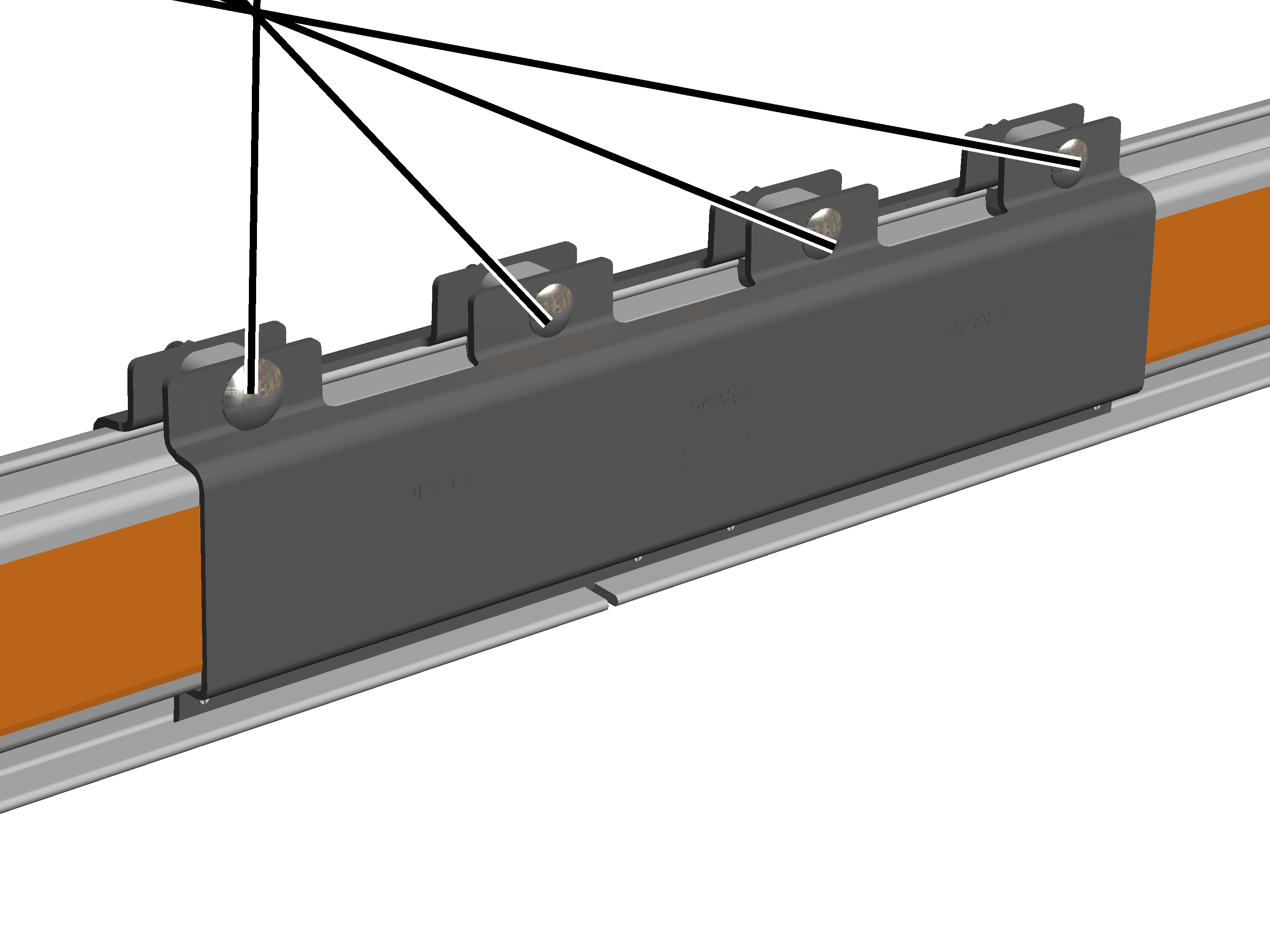
- Inspect the M12 cup square bolts. They must be tightened with the correct torque.
- If the cup square bolts are not properly tightened: tighten them to the correct torque.
Checking the spacing of the profile rail sections
On all profile joints on the crane track and on the crane girder:
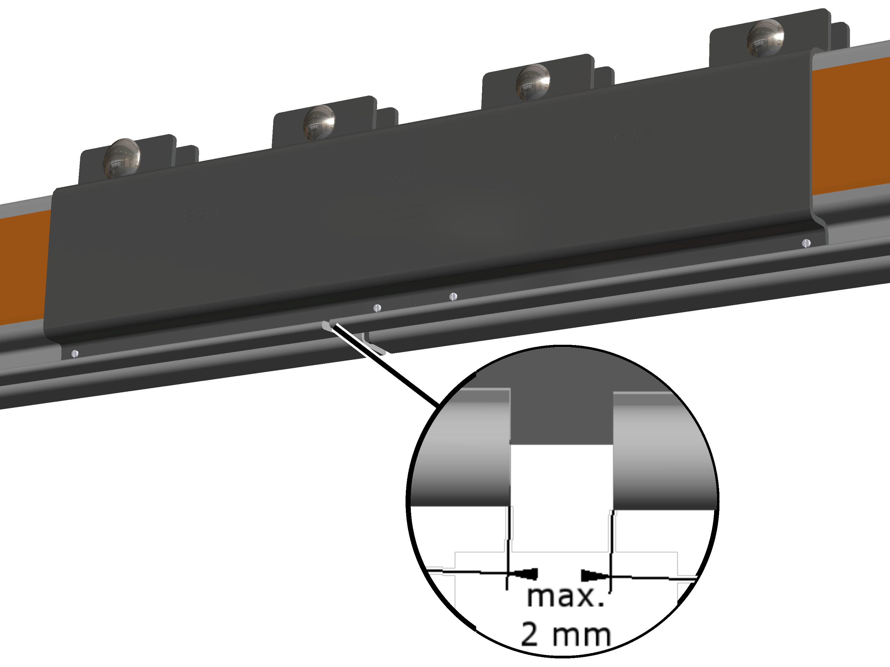
- Check the spacing of the profile rail sections. The profile sections may be spaced maximally 2 mm apart.
- If the distance is greater: release the clamping plates and move the profile sections closer together.
Inspecting the conductor system
Inspecting brackets
On the entire conductor system:
Bracket
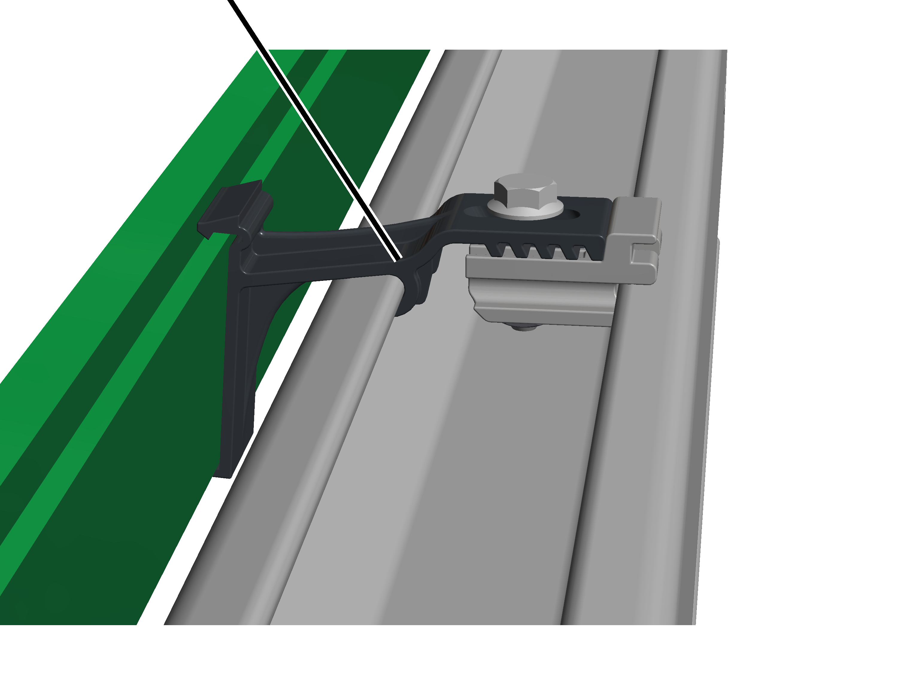
- Inspect the brackets. They should not be broken or otherwise damaged and must clamp firmly in the profile head.
- If a bracket is damaged: replace it.
- If a bracket in the profile head is loose: screw it tight.
Inspecting current collectors
On all current collectors:
Current collector
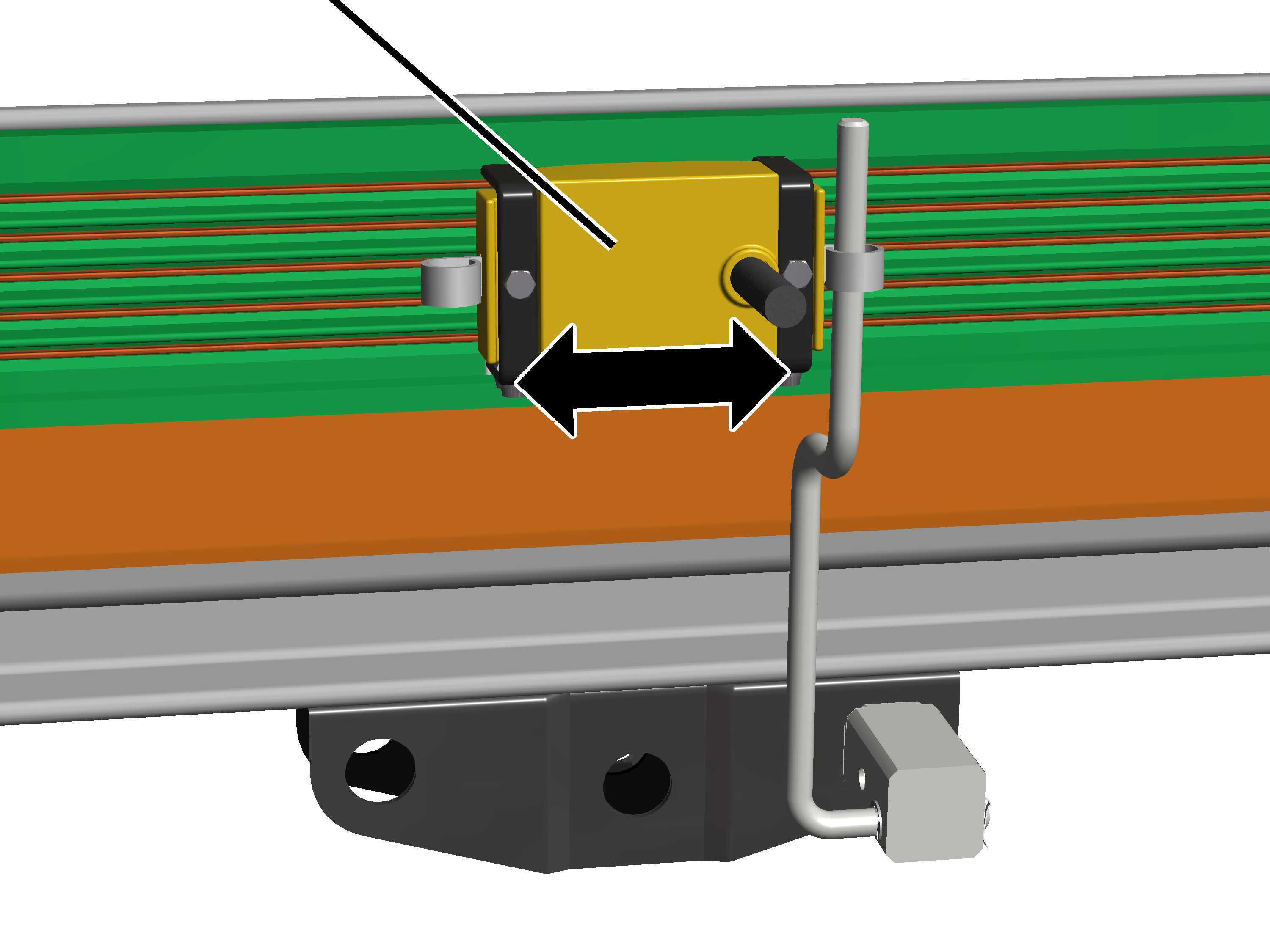
- Inspect the current collector. It must slide with ease in the conductor system.
- If the current collector catches or jerks: remove the current collector and repair it.
Checking the screws on the head
Only with HB crane EHB-X and ZHB-X
On both heads:
Hexagon head screws M12x70
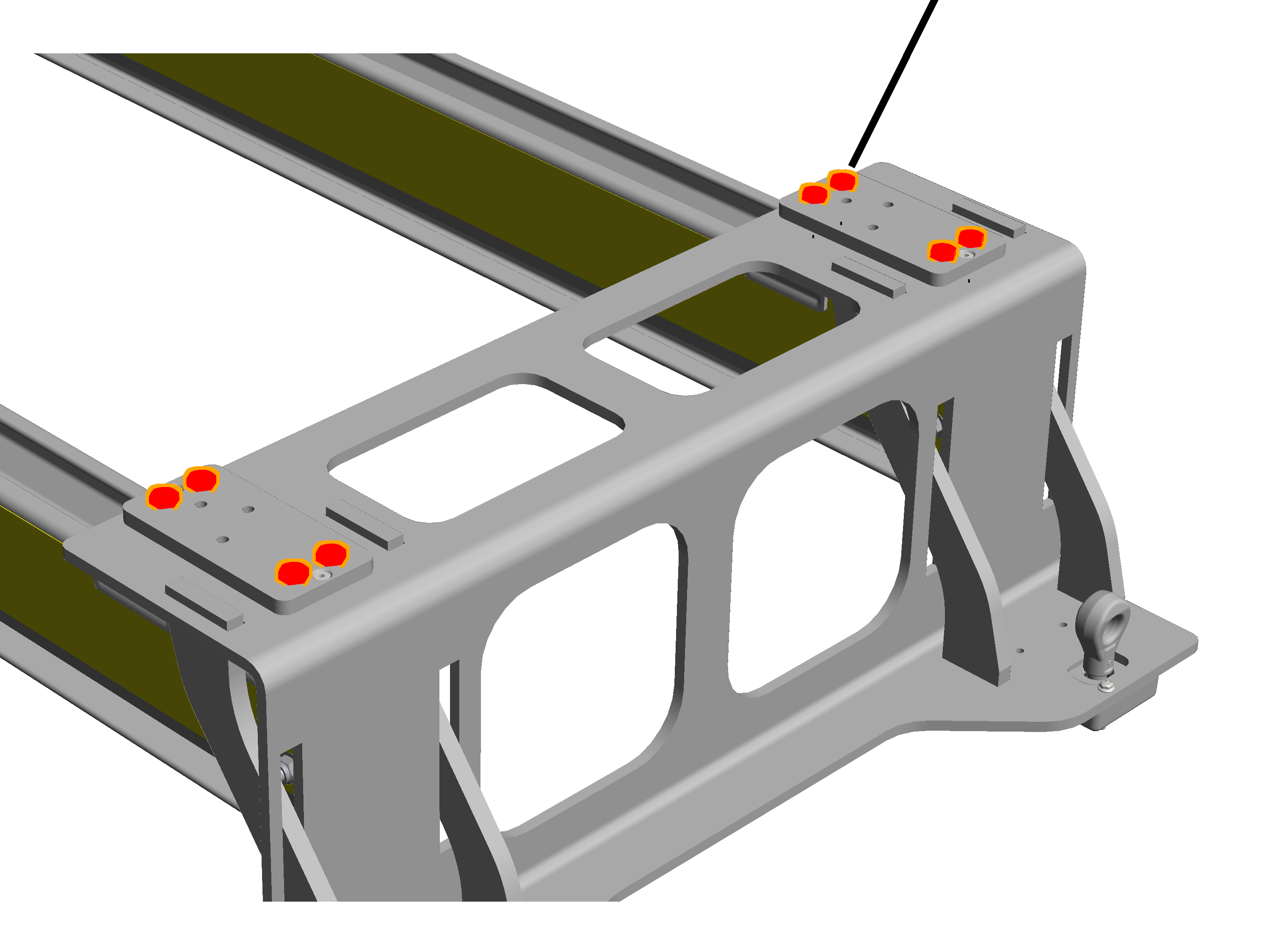
- Check M12x70 hexagon head screws. They must be tightened to 122 Nm.
Maintenance
This section applies to anyone who maintains, repairs or modifies the crane.
The end user of the crane is responsible for the selection and proper qualifications of the maintenance personnel.
Examples of qualified persons:
- Persons with comprehensive knowledge from specialist training in engineering and in the electrical systems of cranes.
- Persons with sufficient experience in the operation, installation and maintenance of cranes.
- Persons with comprehensive knowledge regarding the relevant technical rules, directives and safety regulations applicable in the respective country.
- Persons receiving regular training from ABUS.
ABUS assumes no liability for damage due to incorrectly performed maintenance work done by unqualified personnel.
ABUS recommends having the maintenance work performed by ABUS Service.
Use only original ABUS replacement parts. Otherwise, all warranty claims will be rendered invalid.
Instructions regarding safety when performing maintenance work
Please follow the following safety instructions during all repair work on the crane:
- Switch off the mains switch. Secure the switch to ensure it cannot be turned back on accidentally.
- Unplug the mains disconnector plug from the socket on the crane panel. Secure the socket with a padlock to ensure it is not plugged back in accidentally.
- Use suitable lifting platforms and fall protection equipment.
- Adequately cordon off the operating range around the lifting platform.
- Switch off any other cranes using the same crane track or cranes working above or below the crane undergoing maintenance. Secure the switches to ensure they cannot be turned back on accidentally. Otherwise, other cranes could overturn the hoisting platform or crash into the crane undergoing maintenance.
- Notify personnel in the area that maintenance work will be performed.
- Only trained electricians should work on the crane electrical system!
- Even after the emergency stop button has been pressed, life-threatening high voltages are still present in the panels.
Changing the friction wheel
If the running surface of a friction wheel is damaged, the friction wheel must be replaced.
Disassembling the old friction wheel
Plate springs
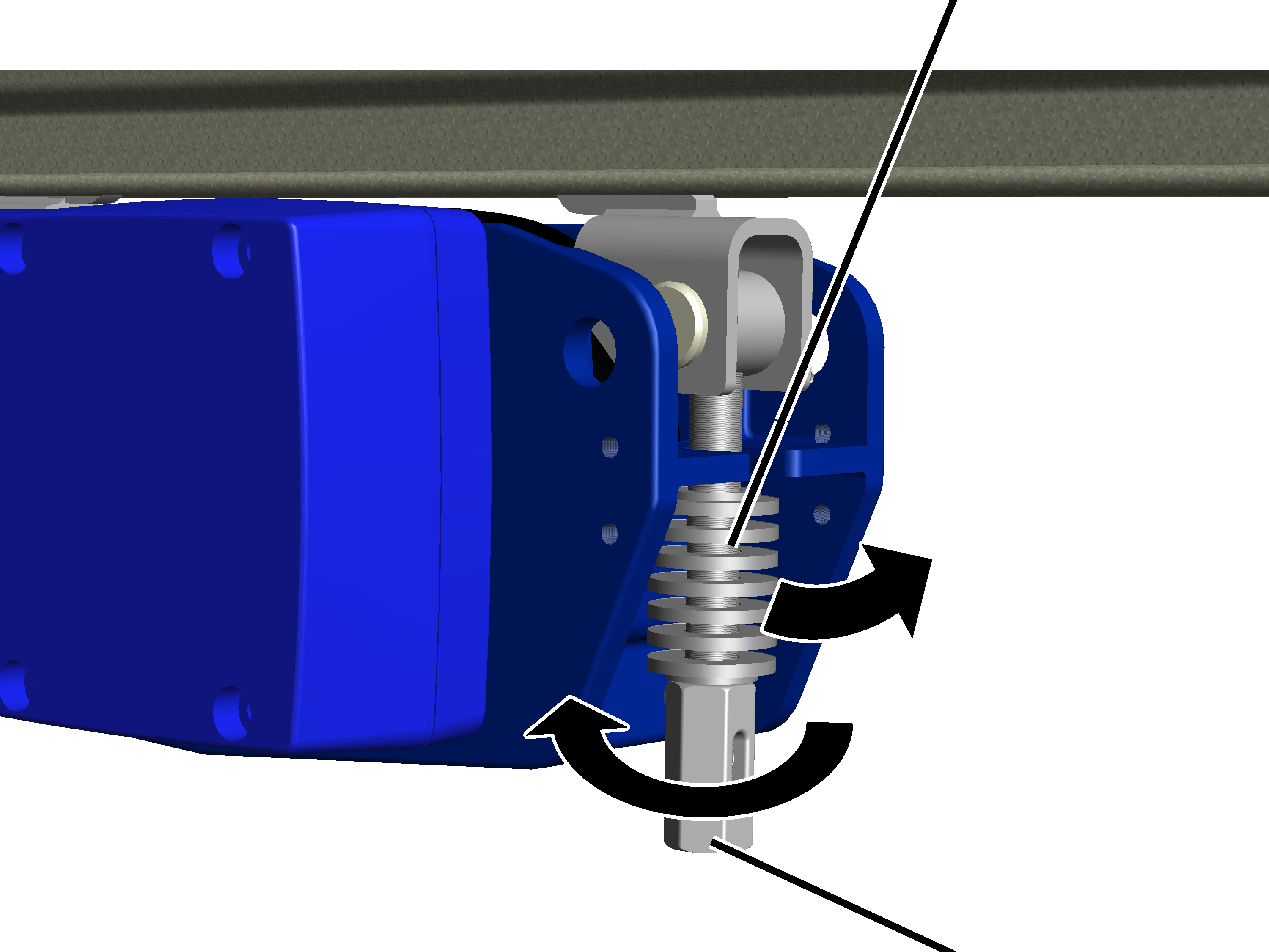
- Release the coupling far enough that the plate springs are completely without tension.
- Hold the HBF drive firmly and fold out the plate springs.
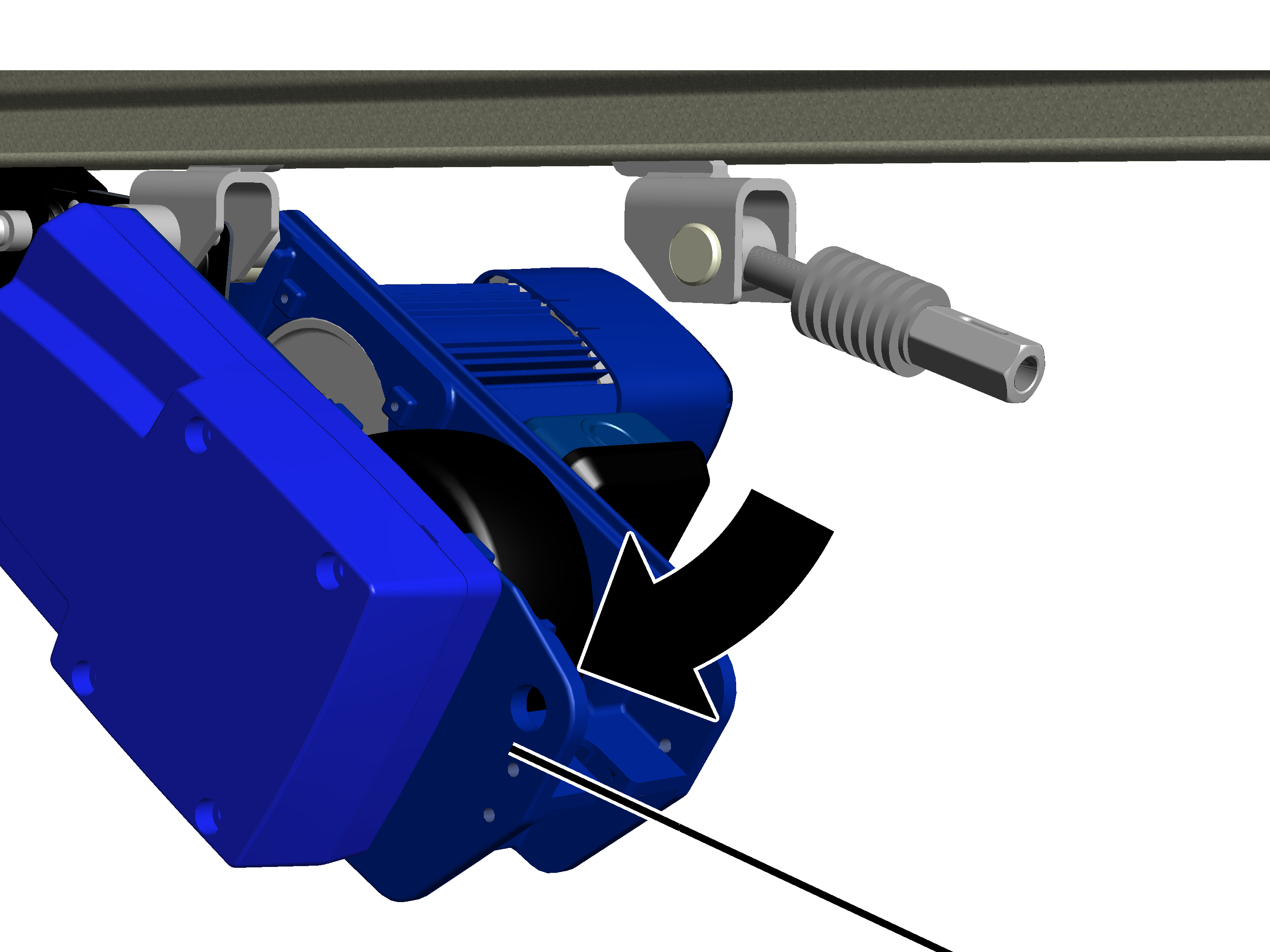
- Tilt the HBF drive downward.
Rib screws M8x16
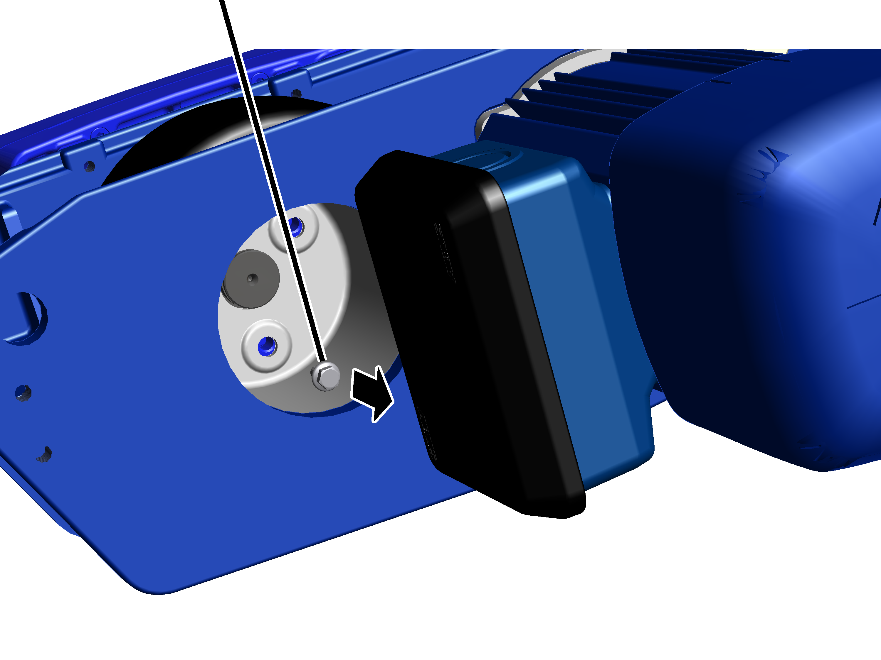
- Release the M8x16 rib screws (3x).
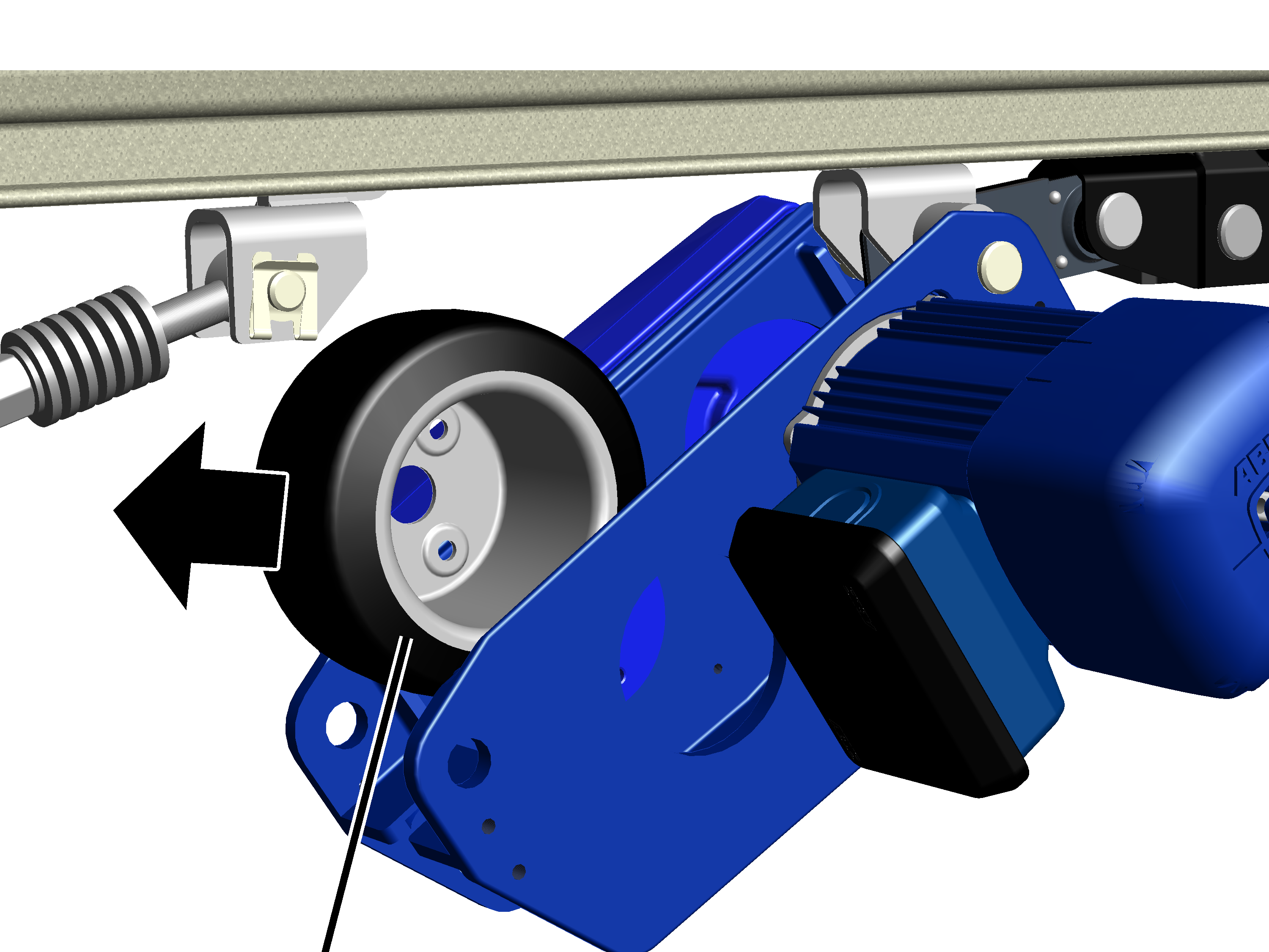
- Remove the friction wheel from the HBF drive by taking it out from the top.
Installing a new friction wheel
Centring hub
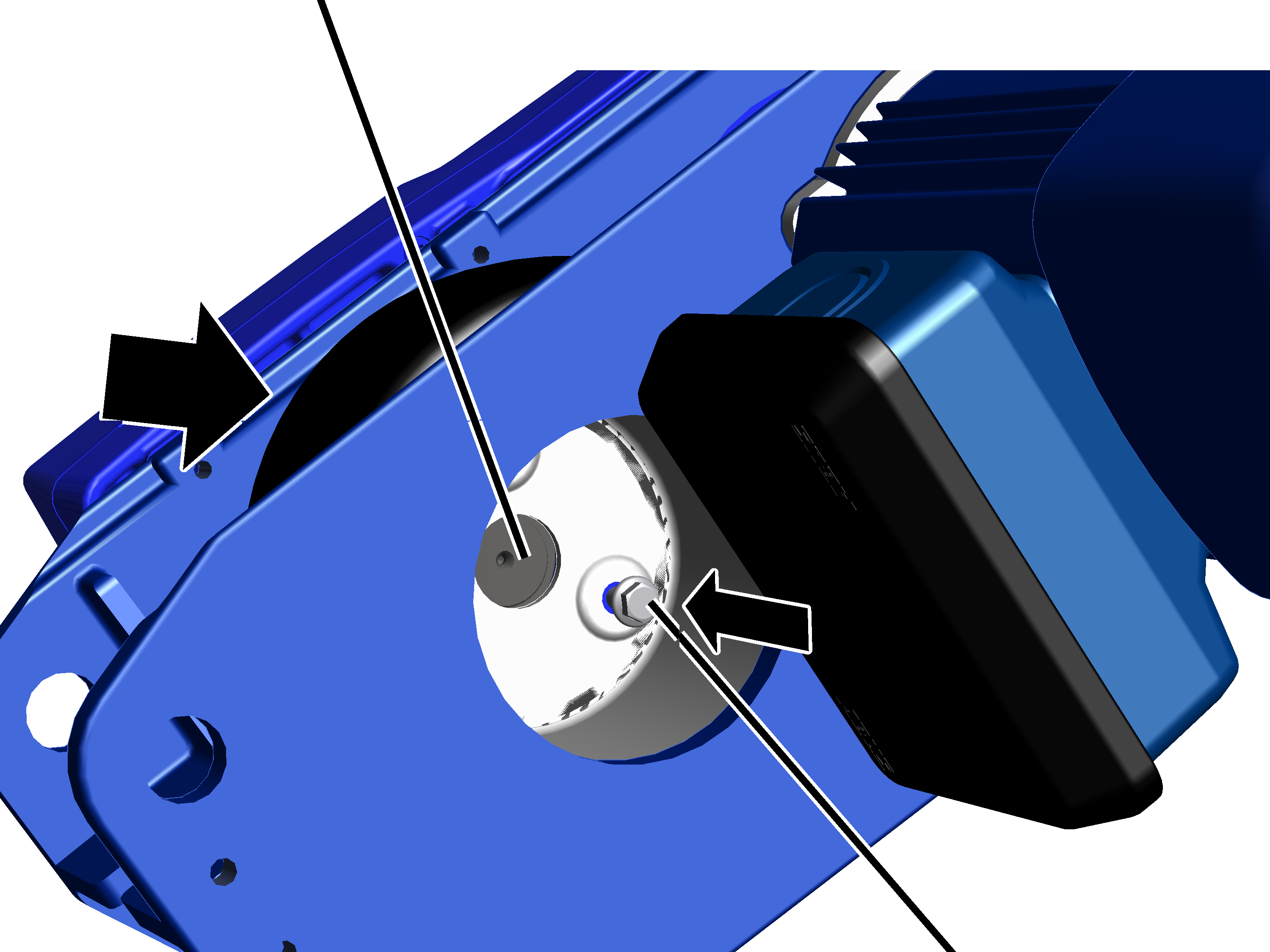
- Insert the new friction wheel and place it on the centring hub.
- Screw on the friction wheel with the M8x16 rib screws (3x) and tighten to 25 Nm.
- Close the cover.
Inserting and tensioning the plate springs
Plate springs
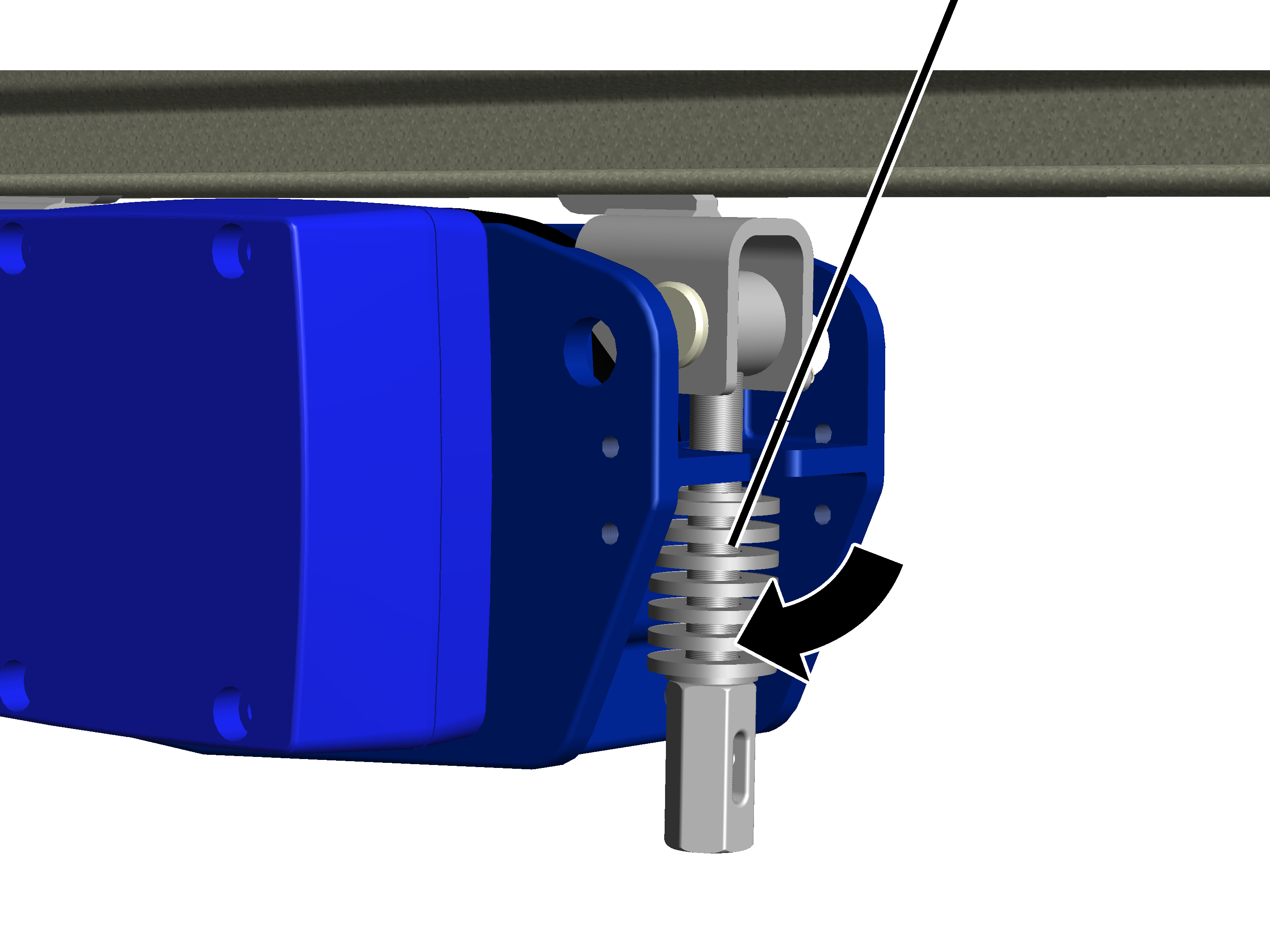
- Insert the plate springs in the recess on the HBF drive.
Plate springs
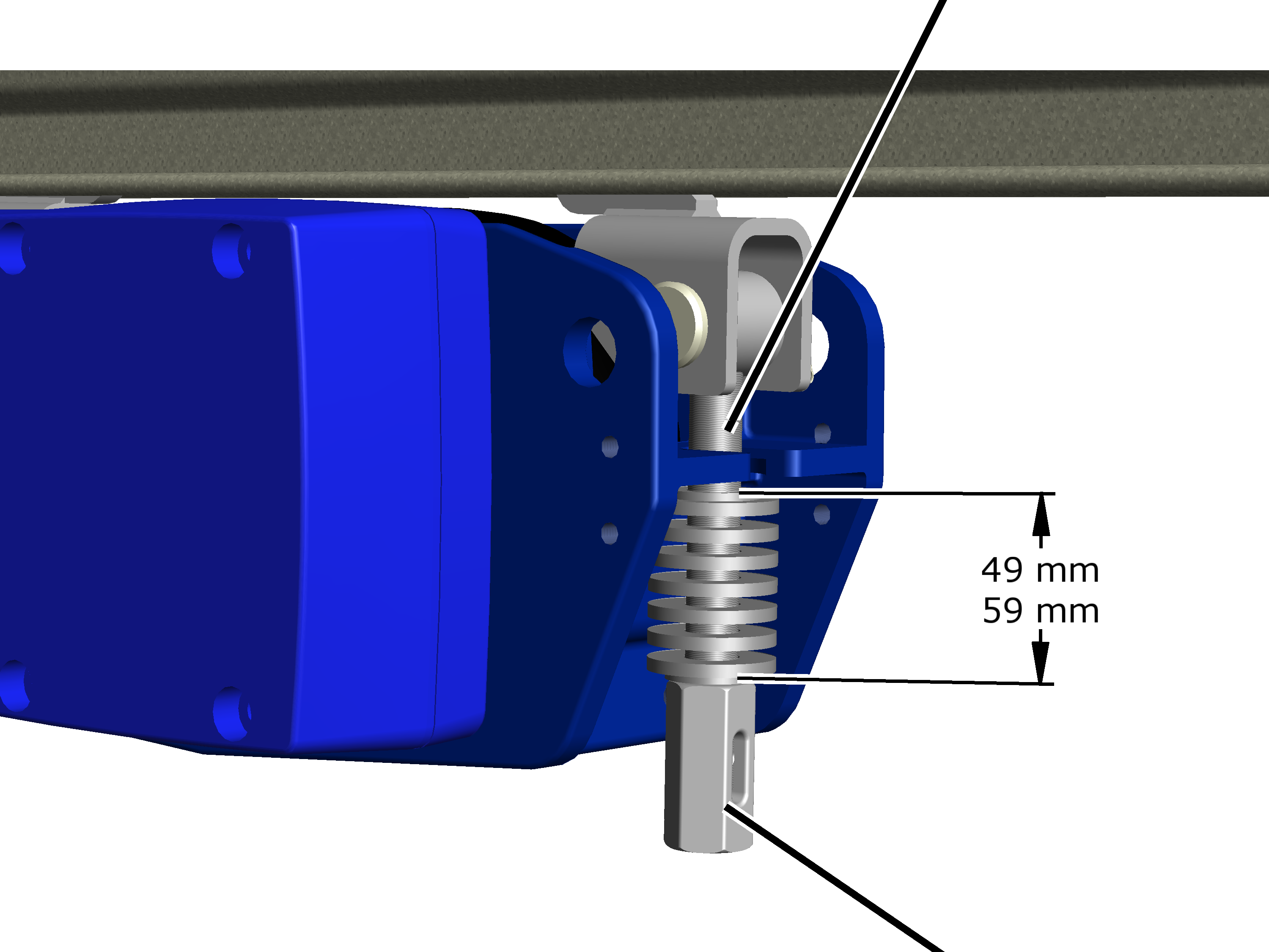
- Turn the coupling far enough so that the plate springs (including the upper and lower discs) are the right length.
- For connection of the HBF drive on the friction wheel side: H = 59 mm.
- For connection of the HBF drive on the travel motor side: H = 49 mm.
- Secure coupling with spring cotter.
- The friction wheel now presses hard enough against the HB profile rail.
Replacing a trolley
If a trolley is not running evenly or you hear rhythmic noises, it must be replaced.
- Remove the entire trolley and replace it with a new one.
Complete trolleys must always be replaced. The trolley wheels may not be removed and replaced by new wheels.
- Also remove the travel mechanism or travel mechanisms on the opposite side of the crane or trolley and install a new trolley or new trolleys.
This ensures the smooth running characteristics of the crane or trolley.
In addition, if there is wear on one of the travel mechanisms, it can be assumed that the opposite travel mechanism is similarly worn.
Setting the air gap on the brake
If the air gap is wider than permitted, it must be readjusted.
Overview:
Dimension |
Value |
|---|---|
Reference gap between brake bearing shield and anchor plate |
Between 3.1 mm and 3.7 mm |
Air gap |
Setting 0.4 mm |
Brake lining thicknessReference gap (between brake bearing shield and anchor plate)
As soon as the travel motor stops running, the anchor plate presses against the fan blade with brake lining through spring force, braking the travel motor. This results in an air gap (which can be measured from the outside by means of the reference gap) between the brake bearing shield and the anchor plate. When the travel motor starts up, the magnet body in the brake bearing shield pulls the anchor plate off the fan blade with the brake lining, allowing the travel motor to freely turn.
If the brake lining is worn, the air gap will be larger. See “Inspecting the brake on the drive”. If the air gap is larger than maximally permitted, the brake must be readjusted. The brake lining must also be replaced if it is worn too thin. See “Replacing the fan blade with brake lining and anchor plate”.
Taking off the fan cover
- Take off the fan cover.
Setting the air gap
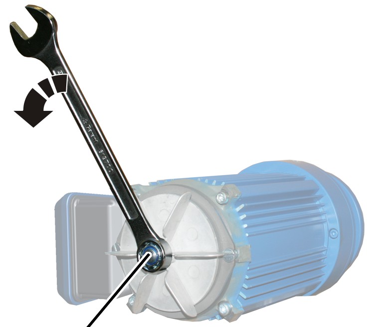
- Hold the fan blade firmly and screw the self-locking nut until hand-tight. The fan blade should just be tight enough that it almost cannot be turned.
- The air gap is now set to 0 mm. This serves as the starting point for the following setting.
The self-locking nut is now released in order to optimally adjust the air gap of the brake. The releasing of the self-locking nut is oriented to the individual segments of the fan blade.
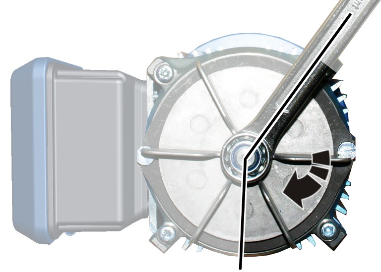
- Hold the fan blade firmly and release the self-locking nut by the amount of two and one half segments of the fan blade.
- The air gap is now set to the optimal width of 0.4 mm.
- To make sure, check that the distance between the brake bearing shield and the anchor plate (reference gap) is between 3.1 mm and 3.7 mm. See “Inspecting the brake on the drive”.
Closing the fan cover
- Attach fan cover.
Replacing the fan blade with brake lining and anchor plate
If the brake lining on the drive is thinner than permitted, then the fan blade with brake lining must be replaced.
When replacing the fan blade with brake lining, it is recommended that the anchor plate be replaced as well.
Taking off the fan cover
- Take off the fan cover.
Removing the fan blade with brake lining
Fan blade with brake lining
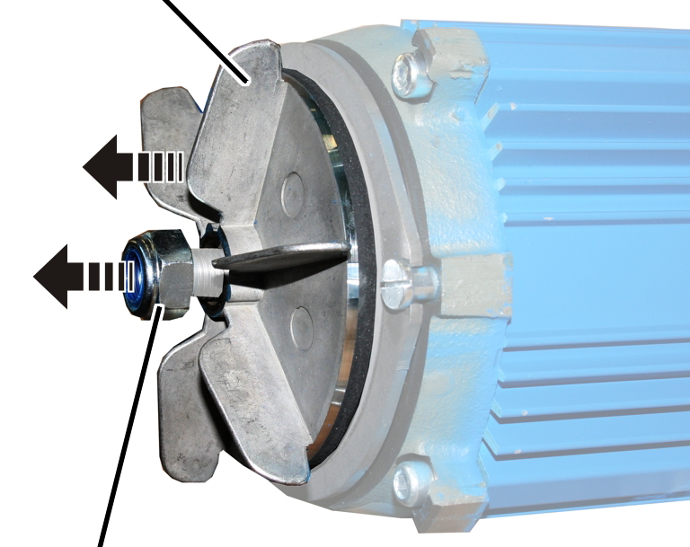
- Hold the fan blade firmly and unscrew the self-locking nut.
- Remove the fan blade with brake lining.
Removing the anchor plate
When replacing the fan blade with brake lining, it is useful to replace the anchor plate as well. If the anchor plate is not to be replaced, this section may be skipped.
Anchor plate
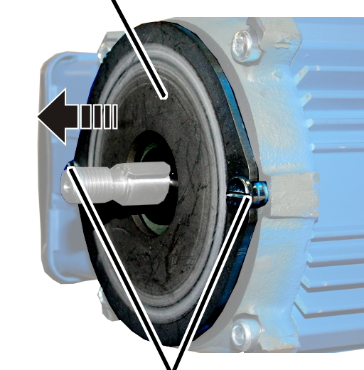
- Screw the collar screws (2x) out.
- The anchor plate is pressed away from the motor. It is tensioned by a spring.
- Remove the anchor plate. Ensure that the compression springs do not fall out.
Replacing the O-ring, plate springs, compression springs and feather key
If the O-ring, plate springs, compression springs or the feather key are missing or damaged, they must be replaced. If the components are in a good condition, this section may be skipped.
Removing damaged components:
- Pull the plate springs and feather key from the motor shaft.
- Pull the O-ring and compression springs from the brake bearing shield.
Replacing components:
Plate springs
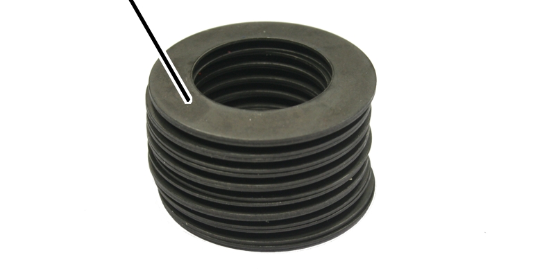
- Assemble the plate springs as shown in the illustration.
Feather keyPlate springs
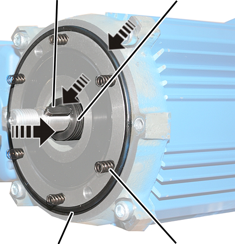
- Push the plate springs onto the motor shaft.
- Insert the feather key.
- Place the O-ring into the groove on the brake bearing shield.
- Insert the compression springs.
Type & size |
Power (see type plate) |
Number of compression springs |
|---|---|---|
HBF drive |
0.18 kW |
4 |
HBF drive |
0.28 kW |
6 |
Installing the anchor plate
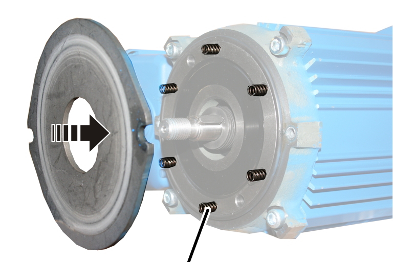
- Insert new anchor plate and press it against the compression springs.
- Clean the collar screw thoroughly.
The collar screws were previously bolted with a thread lock coating or a thread lock. The residues must be completely removed before the collar screw may be used again.
- Apply thread lock (medium-strength) to the thread of the collar screw.
When doing so, ensure that not too much thread lock is applied so that it does not emerge out of the thread.
If a thread lock coating has been applied to the collar screw, no thread lock may be used!
- Tighten the collar screws (2x). 5–7 Nm.
Mounting the fan blade with brake lining
Fan blade with brake lining
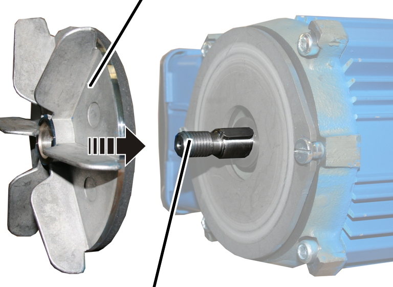
- Slide the new fan blade with brake lining onto the motor shaft.
- Screw the new self-locking nut loosely to the motor shaft.
Do not use the old self-locking nut.
Setting the air gap
- Hold the fan blade firmly and screw the self-locking nut until hand-tight. The fan blade should just be tight enough that it almost cannot be turned.
- The air gap is now set to 0 mm. This serves as the starting point for the following setting.
The self-locking nut is now released in order to optimally adjust the air gap of the brake. The releasing of the self-locking nut is oriented to the individual segments of the fan blade.
- Hold the fan blade firmly and release the self-locking nut by the amount of two and one half segments of the fan blade.
- The air gap is now set to the optimal width of 0.4 mm.
- To make sure, check that the distance between the brake bearing shield and the anchor plate (reference gap) is between 3.1 mm and 3.7 mm. See “Inspecting the brake on the drive”.
Closing the fan cover
- Attach fan cover.
Lubricants
Only for HB crane with HBF drive
Gear unit in drives HBF 520, HBF 1040
Lubrication ex works using lubricant “ISO-VG 460”.
Quantity: 400 ml
- The gear unit in the drive is lubricated for its entire service life. At the end of its service life (in a general overhaul), assess whether the lubricant needs to be changed.
ABUS Service
Only in Germany
- If available, have the product number, serial number and customer number handy.
- Call the ABUS Service Centre:
- Phone: +49-2261-37-237
- If calling outside the usual business hours, leave a message on the answering machine.
- ABUS Service will return your call promptly.
- If necessary, send a description of the problem by fax or e-mail:
- Fax: +49-2261-37-265
- E-mail: service@abus-kransysteme.de
Only outside Germany
- Call the local ABUS branch or crane service partner.
Your local ABUS branch or crane service partner will provide details of contact data, contacts and availability.