
AT A GLANCE:
General information
This section applies to anyone who lifts loads using the crane, performs work on the crane, or works nearby.
Read before starting work
Using this product manual
The following symbols are used in this product manual:
- This is an instruction regarding an action and prompts you to perform a work step.
- This is the result of an action and describes what happens on the device.
- This is a list.
Only with...
A section that appears in a box framed by a dashed line is only applicable for certain types, versions or options. The condition to which the section applies is specified at the beginning in the heading “Only with...”.
Instructions for the product manual
Read the product manual through carefully before starting work. Also be sure to observe additional product manuals for accessories and components.
Afterwards, keep the product manual available in the vicinity of the crane. It must be accessible to all who work with or on the crane.
If the crane is sold on or hired out, always provide the product manual together with the crane.
Proper use
The hoist drive is provided as the drive unit on a single-rail trolley (types E, S and U) and double-rail trolley (types D, DA, DQA, Z and ZA).
The output shaft of the hoist drive is connected directly with the cable drum.
- The hoist drive can be controlled in a pole-switchable manner with two different hoist speeds using ABUS electrics 3 or ABUControl, as well as continuously with a frequency converter in ABULiner or ABUControl.
- The hoist drive can be used as a drive in other machines within its electrical and mechanical performance limits.
- The hoist drive cannot be operated in a delta connection.
Regulations
The installation has been built and tested according to European standards, rules and regulations applicable at the time of its manufacture. The conventions applied during design and construction are specified in the Declaration of Conformity or the Declaration of Incorporation. The conventions must also be observed for installation, operation, inspection and maintenance, as must the applicable occupational health and safety regulations.
Which provision applies in individual cases will greatly depend on the crane’s use and the national regulations. Review and observe all applicable and current regulations, including the occupational health and safety regulations. Refer also to the Declaration of Conformity or Declaration of Incorporation.
Warranty
- ABUS assumes no liability for damages that were caused by improper use, inadequately trained personnel, incorrect performance of work, nor for any changes, reconstruction or other modification of the crane or crane components which were not approved by ABUS.
- Any warranty claim becomes invalid if components were modified without consent, the crane or crane components were installed, used or serviced in any way other than that described in this product manual, or if parts other than original ABUS replacement parts were used.
- Safe operation of the crane or crane components is only guaranteed if original ABUS replacement parts are used.
Instructions regarding safety
Observe these instructions for safe handling of the crane. Special hazard notices are located in the corresponding sections in which the danger arises.
- Danger through rotating parts! If a hoist drive is not mounted, the output shaft is not protected. If the non-mounted hoist drive is operated, the output shaft is a source of danger (e.g. it can become caught in loose parts). Do not operate the hoist drive if it is not mounted or take suitable measures to ensure safety.
- Do not permanently remove the fan cover! If the fan cover is removed, hazardous areas are no longer protected. This can result in persons being injured! Remount the fan cover after working on the hoist drive. Do not permanently remove the fan cover to improve cooling.
The hoist drive
Description of the device
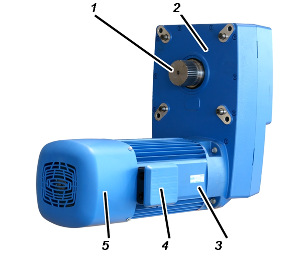
- 1: Output shaft with gearing
- 2: Gear unit
- 3: Hoist motor
- 4: Connector housing
- 5: Fan cover
Performance features
The pole-switchable hoist drive GM 800 to 7000:
- The hoist drive is powered by a pole-switchable 2/12-pole hoist motor with gear unit.
- The hoist motor features an electro-magnetically actuated spring-loaded brake.
- The hoist drive has a slow lifting speed and a fast lifting speed. The ratio of the two lifting speeds is 1:6.
- Using plug-in connections in the connector housing directly on the hoist drive, the hoist drive can be quickly separated from the rest of the crane’s electrics.
- The hoisting gear features a multi-stage, helical spur gear in an alloy housing. The gear wheels run in a sealed oil bath, which ensures they remain lubricated over their full service life.
Technical data
see test log book of crane.
Loading and unloading the hoist drive
Observe the following points amongst others:
Only with direct slinging
With direct slinging, the hoist drive is not suspended horizontally. The ABUS assembly aid AN 103574 should be used for assembly on the wire rope hoist.
Eyebolt
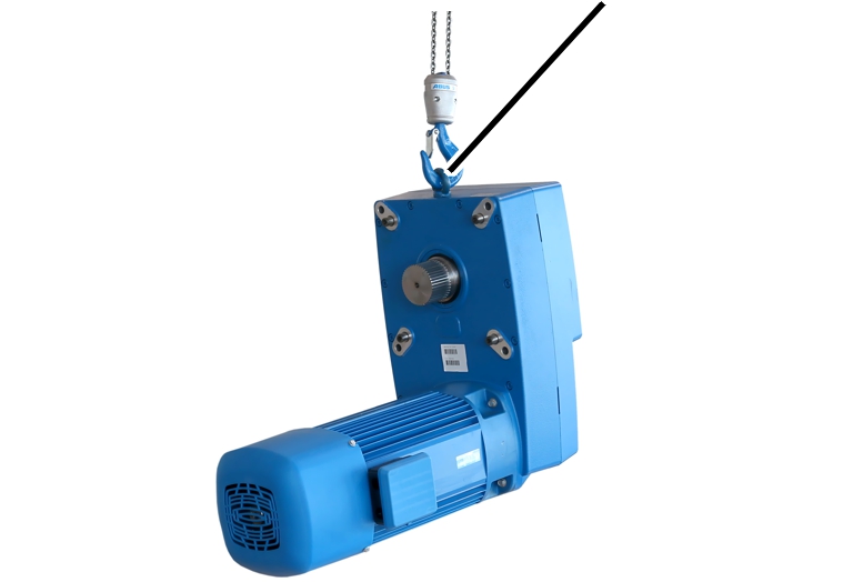
- Screw suitable eyebolt into the hoist drive.
- Sling suitable lifting tackle into the eyebolt and lift the hoist drive.
- The hoist drive is not suspended horizontally.
Only for slinging with assembly aid
The ABUS assembly aid AN 103574 should be used for assembly on the wire rope hoist.
Assembly aidAnti-rotation
device
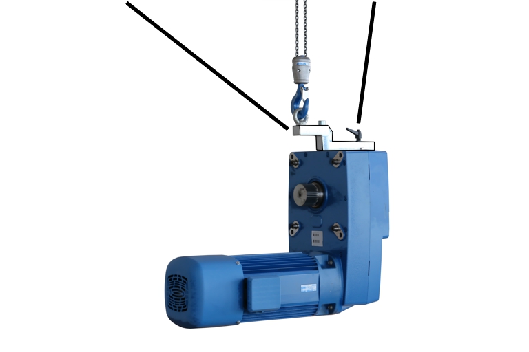
- Screw assembly aid into the hoist drive.
- Release anti-rotation device, push it against the hoisting gear and screw tight.
- Sling suitable lifting tackle into the assembly aid and lift the hoist drive.
- The hoist drive is suspended horizontally.
Disposing of the hoist drive
If the hoist drive needs to be disposed of:
- Dismantle the hoist drive to the extent possible.
- Observe local regulations concerning disposal and recycling.
- Dispose of the individual parts sorted by material in an environmentally sound manner.
- Dispose of metal parts as scrap metal.
The hoist motor stator is permanently shrunk into the housing. Cut the housing open to separate the stator from the housing.
- Plastic parts should be recycled with plastic waste.
- Dispose of brake linings as multiple components (hazardous waste).
- Remove oil or grease from the hoist drive and dispose of as a lubricant.
- Dispose of cables and plug-in connections as scrap electronic parts.

Installing and connecting
This section applies to anyone who works on the crane prior to its use
The end user of the crane is responsible for the proper qualifications of the commissioning personnel.
Examples of qualified persons:
- Persons with comprehensive knowledge from specialist training in engineering and in the electrical systems of cranes.
- Persons with sufficient experience in the operation, installation and maintenance of cranes.
- Persons with comprehensive knowledge regarding the relevant technical rules, directives and safety regulations applicable in the respective country.
- Persons receiving regular training from ABUS.
ABUS assumes no liability for damage due to incorrectly performed commissioning work done by unqualified personnel.
ABUS recommends having the commissioning work performed by the ABUS assembly team.
Installing the hoist drive
The images show the installation of a GM 5000 hoist drive on a double-rail trolley (type D). The installation of a hoist drive on a single-rail trolley or in a different size does not essentially differ.
Lifting the hoist drive
- Determine the weight of the hoist drive. See separate "Technical data" document of the corresponding hoist drive.
Assembly aidAnti-rotation
device
- Screw assembly aid into the hoist drive.
- Release anti-rotation device, push it against the hoisting gear and screw tight.
- Sling suitable lifting tackle into the assembly aid and lift the hoist drive.
Alternatively, the hoist drive can also be lifted with a suitable eyebolt. However, the hoist drive is then not suspended horizontally, which can make the installation considerably more difficult.
See also “Loading and unloading the hoist drive”.
Sealing and lubricating the output shaft
If necessary, the output shaft with new components can be sealed and relubricated.
Seal ringOutput shaft
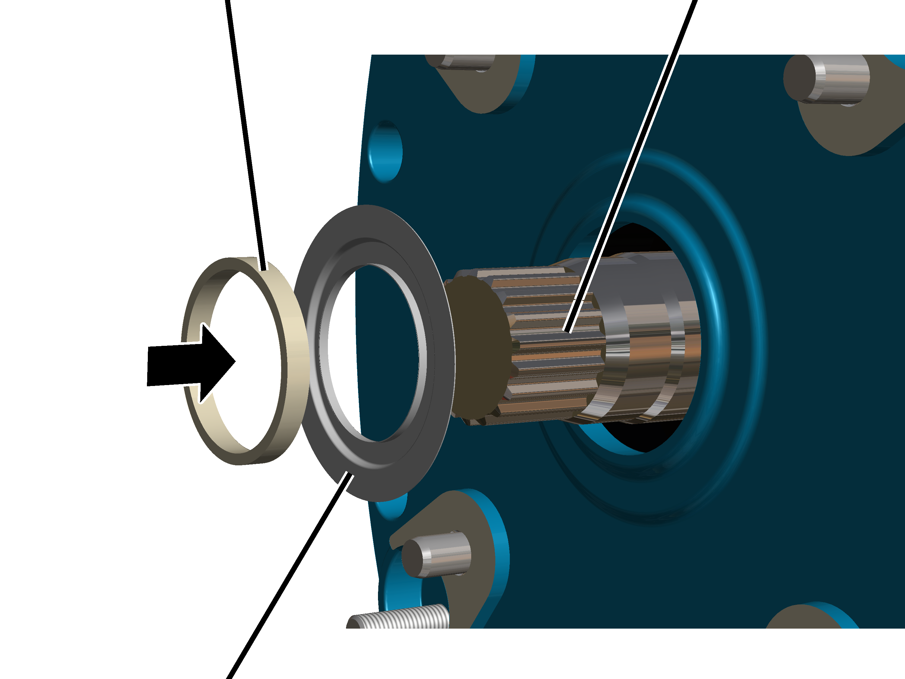
Shim washer (for GM1000 to GM7000)
- Push the Nilos ring (for GM800) or shim washer (for GM1000 to GM7000) onto the output shaft.
- Slide the seal ring onto the output shaft.
- Only with GM6000: If an additional second seal ring was previously mounted, also slide on the second seal ring now.
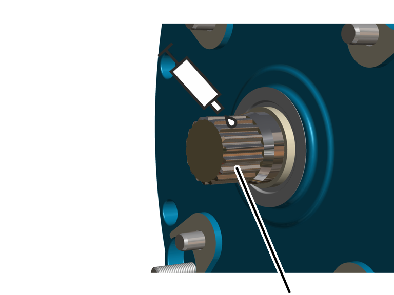
- Lubricate the gearing on the output shaft.
Lubricant - Fuchs Lubritech high temperature paste PBC 1574.
Cover in the bearing flange of the cable drum
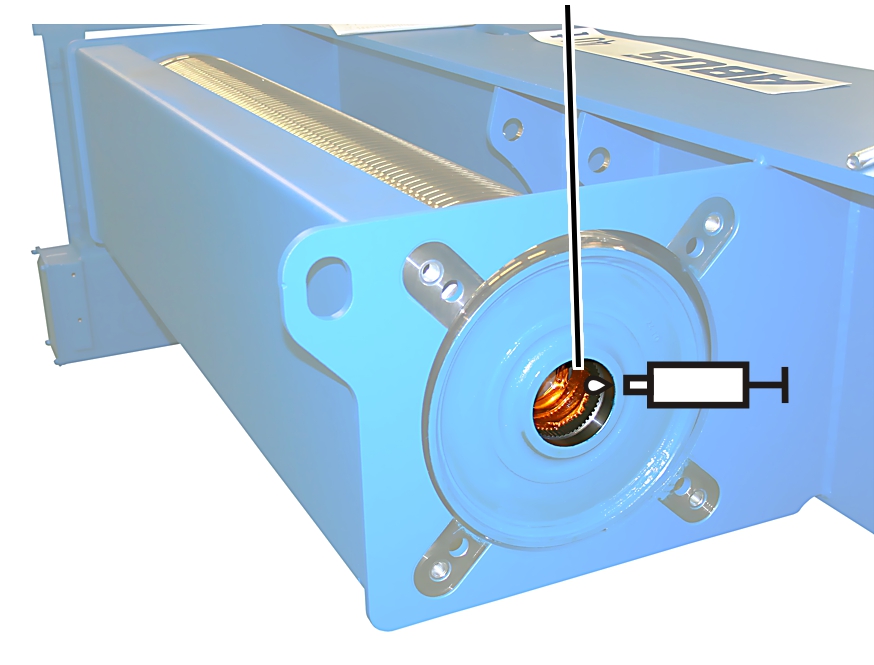
- Lubricate the cover behind the bearing flange of the cable drum.
Lubricant - high temperature paste PBC 1574 SF item number 303678.
Quantity GM 800: 25 g
Quantity GM 1000: 25 g
Quantity GM 2000: 50 g
Quantity GM 3000: 50 g
Quantity GM 5000: 70 to 75 g
Quantity GM 6000: 70 to 75 g
Quantity GM 7000: 70 to 75 g
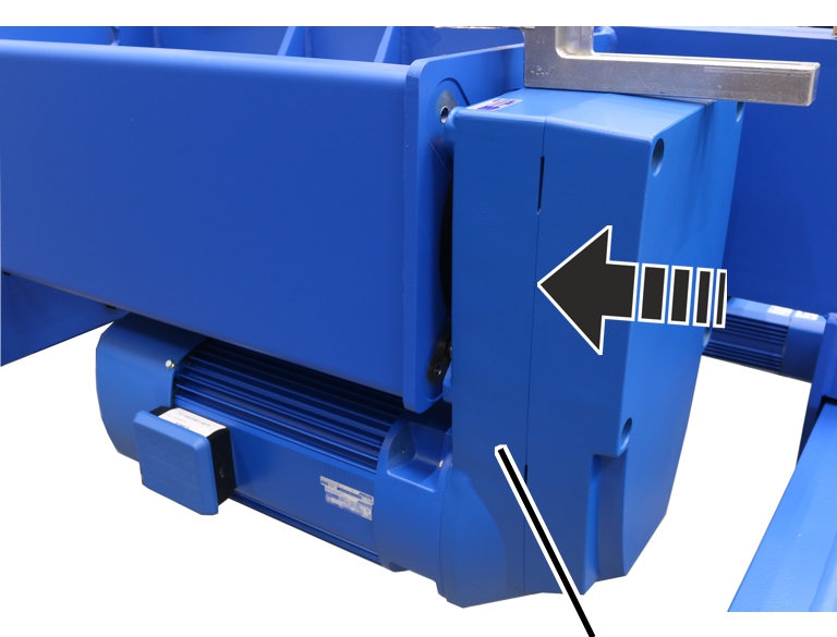
- Push the output shaft of the hoist drive into the bearing flange of the cable drum.
Fillister-head screws
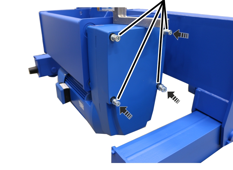
- Screw the hoist drive in place using fillister-head screws (4x) and washers (4x).
Size |
Size and length |
Tightening torque |
|---|---|---|
GM800.4 |
M10x110 |
40 Nm |
GM1000.6 |
M12x120 |
85 Nm |
GM2000.3 |
M12x120 |
85 Nm |
GM3000.4 |
M12x160 |
85 Nm |
GM5000.3 |
M16x210 |
210 Nm |
GM6000.4 |
M16x220 |
210 Nm |
GM7000.1 |
M20x270 |
425 Nm |
Connecting the hoist drive
Checking the mains supply
- Compare the operating voltage and frequency range on the type plate with the mains voltage and frequency of the local grid.
Connecting the hoist drive
Only with contactor control
Connection cables of hoist drive
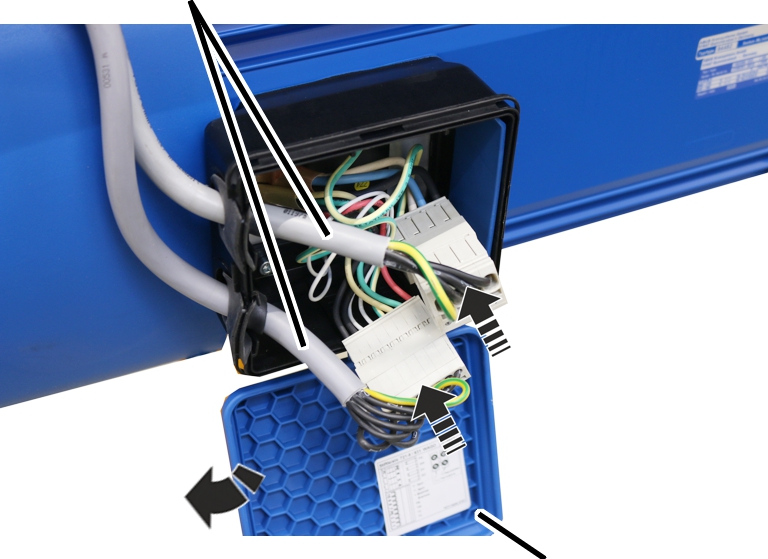
- Open the housing cover.
- Insert the connection cables for the hoist drive into the pin multipoint connectors on the hoist drive.
Depending on size and options, the plug-in connections are of different sizes and differently assigned.
- Lay the plug-in connections and connection cable in the connector housing.
- Close the housing cover.
Only with frequency converter
Connection cablesPlug-in
connections
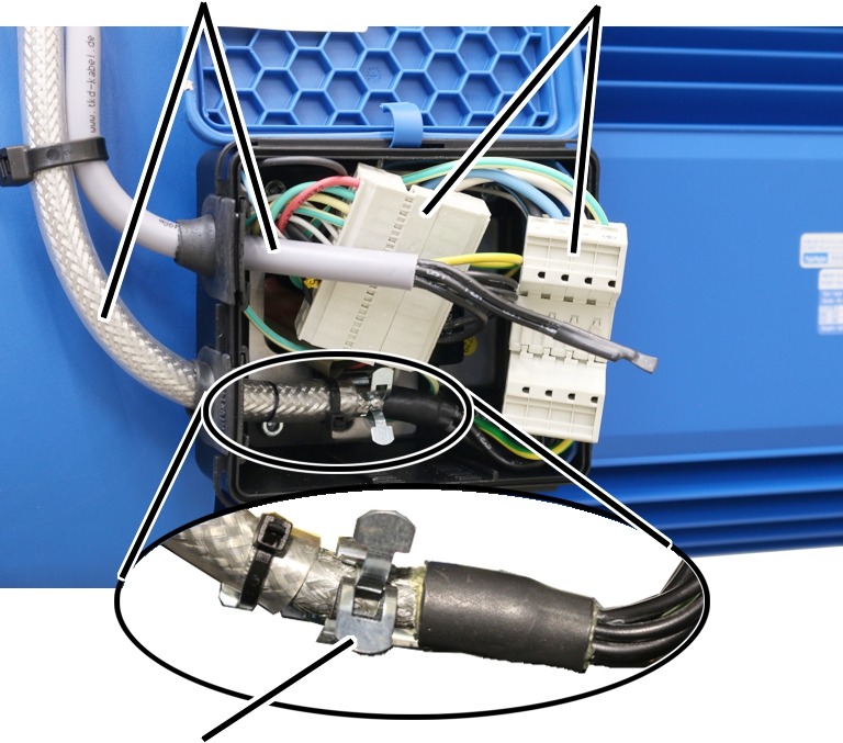
- Open the housing cover.
- Insert the connection cables for the hoist drive into the pin multipoint connectors on the hoist drive.
Depending on size and options, the plug-in connections are of different sizes and differently assigned.
- Lay the plug-in connections and connection cable in the connector housing.
- Push the front end of the hoist drive connection cable (where the sheathing around the shield has been removed) into the screening clamp connection.
- Fasten the connection cable to the screening clamp connection using cable ties.
- Lay the plug-in connections and connection cable in the connector housing.
- Close the housing cover.
Inspection
This section applies to anyone who inspects and accepts the crane in accordance with occupational health and safety requirements
The hoist drive must be regularly inspected in order to guarantee safe operation. The end user is responsible for this regular inspection.
At the start
Test intervals
The regular inspection is performed at least once annually.
Under certain conditions, more frequent regular inspections may be necessary. Reasons include:
- Frequent operation at the load capacity
- Working in multiple shifts
- Frequent use
- Dusty or chemically aggressive environment
The end user is responsible for checking the requirements and determining the test intervals. ABUS will gladly assist you if questions arise.
Requirements for the examiner
The end user of the crane is responsible for the proper qualifications of the examiner.
Examples of qualified persons:
- Persons with comprehensive knowledge from specialist training in engineering and in the electrical systems of cranes.
- Persons with sufficient experience in the operation, installation and maintenance of cranes.
- Persons with comprehensive knowledge regarding the relevant technical rules, directives and safety regulations applicable in the respective country.
- Persons receiving regular training from ABUS.
Scope of the test
The qualified person inspecting the hoist drive is responsible for the type and scope of the test.
Overview: Inspecting the hoist drive
In addition to the points described here, all points outlined in the other supplied product manuals must also be checked.
The decision as to whether the hoist drive is in perfect condition may be made only by the examiner. Any inadequacies, if found, must be eliminated. The examiner decides whether the hoist drive has to be tested again afterward.
If locally applicable regulations specify further tests, these are likewise to be carried out.
Additionally, at least the following points must be checked:
- Inspect the brake on the hoist drive. See “Inspecting the brake on the hoist drive”.
Inspecting the brake on the hoist drive
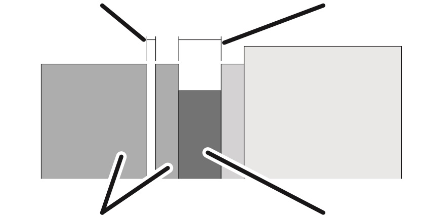
To check the brake, a measurement is made of the air gap between magnet body and anchor plate, as well as the brake lining thickness.
Overview:
Air gap (between magnet body and anchor plate)Brake lining thickness
Dimension |
Value |
|---|---|
Air gap between anchor plate and magnet body |
Between 0.4 mm and 1.1 mm |
Target value for air gap |
0.4 mm |
Size |
Brake lining thickness (minimum) [mm] |
||
|---|---|---|---|
Hoist motor L6 |
Hoist motor H6 |
Hoist motor U6 |
|
800.4 |
9.3 |
9.3 |
9.3 |
1000.7 |
9.3 |
9.3 |
11.3 |
2000.3 |
9.3 |
11.3 |
- |
3000.4 |
11.3 |
12.3 |
- |
5000.3 |
12.3 |
13.8 |
- |
6000.3 |
13.8 |
- |
- |
7000.1 |
- |
13.8 |
13.8 |
Due to the wear of the brake lining as the motor is braked, the brake rotor gradually becomes thinner. The anchor plate is thereby pressed ever further toward the brake rotor during braking and the air gap thus becomes wider. If the air gap has reached its maximum width, a gap limiter prevents the anchor plate from being pressed any further, thus ensuring that the anchor plate is reliably ventilated. When the gap limiter is employed, the braking effectiveness gradually lessens.
This is the point at which the air gap must be readjusted at the latest. If the minimum lining thickness has been reached, the brake rotor must be replaced.
If the width of the air gap is within the permitted range but usage behaviour leads to the expectation that the air gap will be wider than permitted before the next regular inspection, the air gap must be readjusted now.
Taking off the fan cover
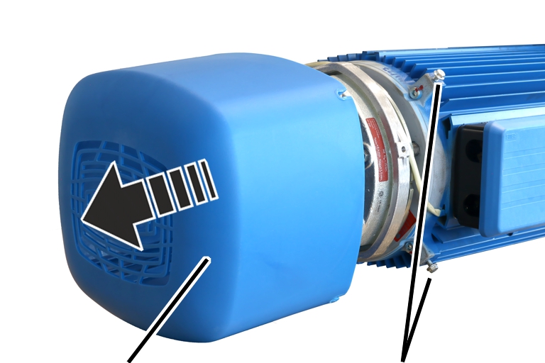
- Unscrew the rib screws (3x) of the fan cover.
- Take off the fan cover.
Only for fan blades on the motor shaft
Removing the fan blade
Circlip
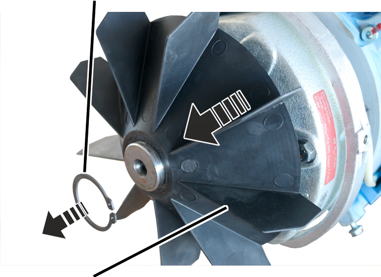
- Remove the circlip.
- Remove the fan blade.
Only for auxiliary fans without frame
Plug-in connection
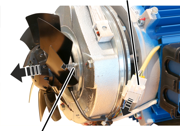
- If present: Unplug the plug-in connection from the auxiliary fan.
- Release the hexagon head screws (3x) on the auxiliary fan and remove the auxiliary fan.
- If the auxiliary fan does not have a plug-in connection: Leave the auxiliary fan connected and secure it on the hoist motor, e.g. with a lashing strap.
Only for auxiliary fans with frame
Plug-in connection
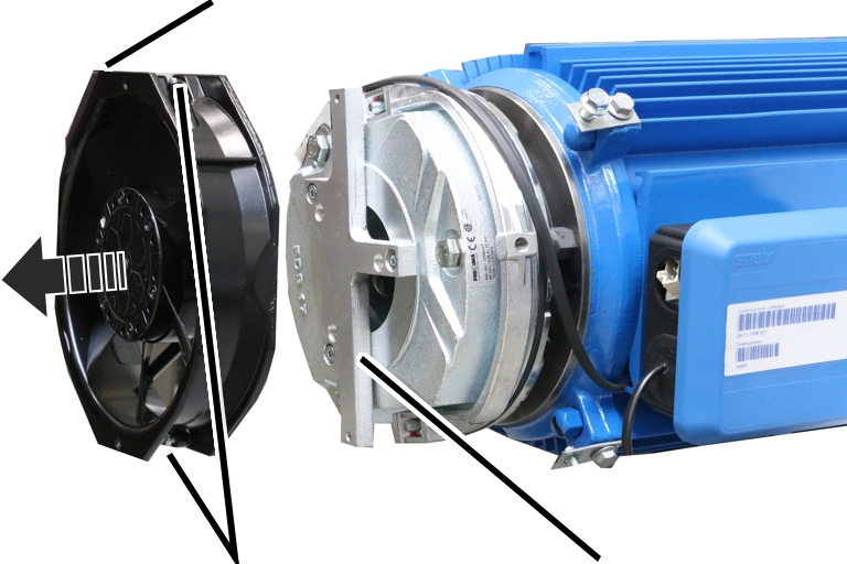
screwMount
- Unplug the plug-in connection from the auxiliary fan.
- Release the fillister-head screws (2x) on the auxiliary fan and remove the auxiliary fan.
Uncovering the brake
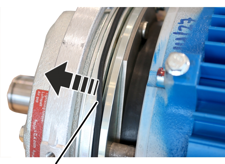
- Remove the O-ring.
- Clean the entire brake with compressed air.
Measuring the air gap
Magnet bodyAnchor plate
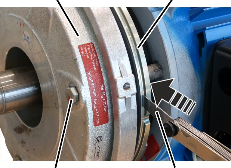
- Insert the feeler gauge next to one of the hexagon head screws in the air gap between magnet body and anchor plate and measure the distance.
- If the air gap has reached the maximum width of the operating range (1.1 mm), adjust the brake. See “Setting the air gap on the brake”.
If the width of the air gap is within the permitted range but usage behaviour leads to the expectation that the air gap will be wider than permitted before the next regular inspection, the air gap must be readjusted now.
- Repeat the steps for all hexagon head screws (3x).
Disassembling the magnet body
Power supplyMagnet body
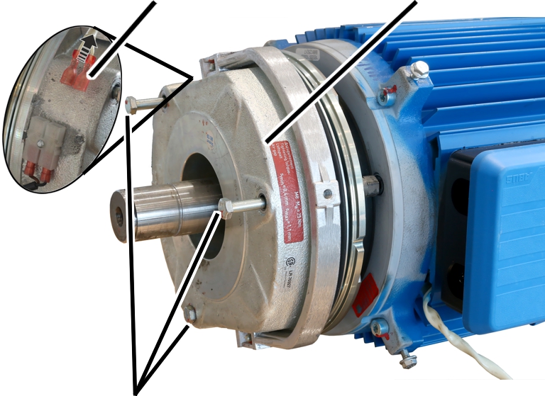
- Disconnect the power supply of the magnet body.
- Release the hexagon head screws (3x).
- Pull the magnet body from the motor shaft.
Measuring brake lining thickness
Brake rotor
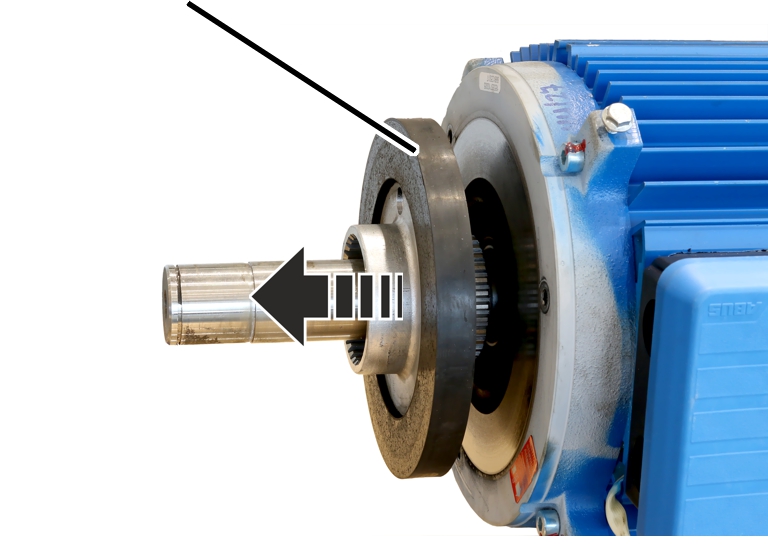
- Pull the brake rotor from the hub and from the motor shaft.
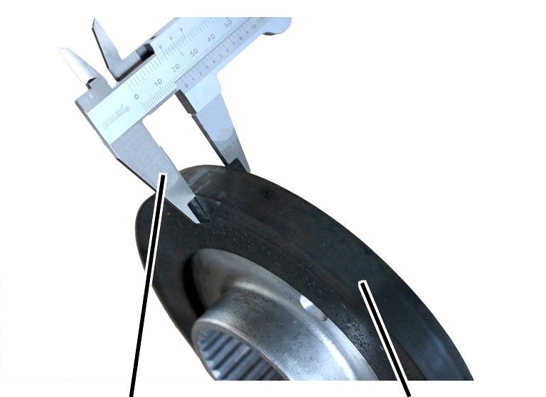
- Check the thickness of the brake lining with a calliper.
- If the brake rotor is thinner than specified in the table: replace the brake rotor. See “Replacing the brake rotor on the hoist drive”.
Size |
Brake lining thickness (minimum) [mm] |
||
|---|---|---|---|
Hoist motor L6 |
Hoist motor H6 |
Hoist motor U6 |
|
800.4 |
9.3 |
9.3 |
9.3 |
1000.7 |
9.3 |
9.3 |
11.3 |
2000.3 |
9.3 |
11.3 |
- |
3000.4 |
11.3 |
12.3 |
- |
5000.3 |
12.3 |
13.8 |
- |
6000.3 |
13.8 |
- |
- |
7000.1 |
- |
13.8 |
13.8 |
Checking the O-ring
The area (air gap) between the magnet body and the anchor plate is protected from dust by an O-ring. The O-ring must not become damaged or missing.
- Check the O-ring.
The O-ring may not be torn, dented or otherwise damaged, nor may it be missing completely.
- If the O-ring is damaged or missing, fit a new O-ring.
Installing the brake rotor
Hub
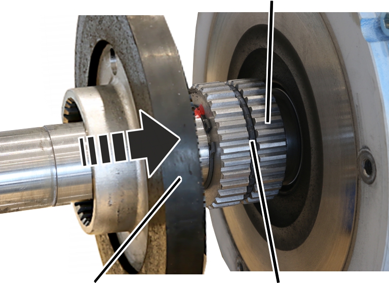
- If present: Check whether the O-ring lies fully in the groove of the hub.
- Slide the brake rotor over the motor shaft onto the hub.
Mounting the magnet body
Magnet body
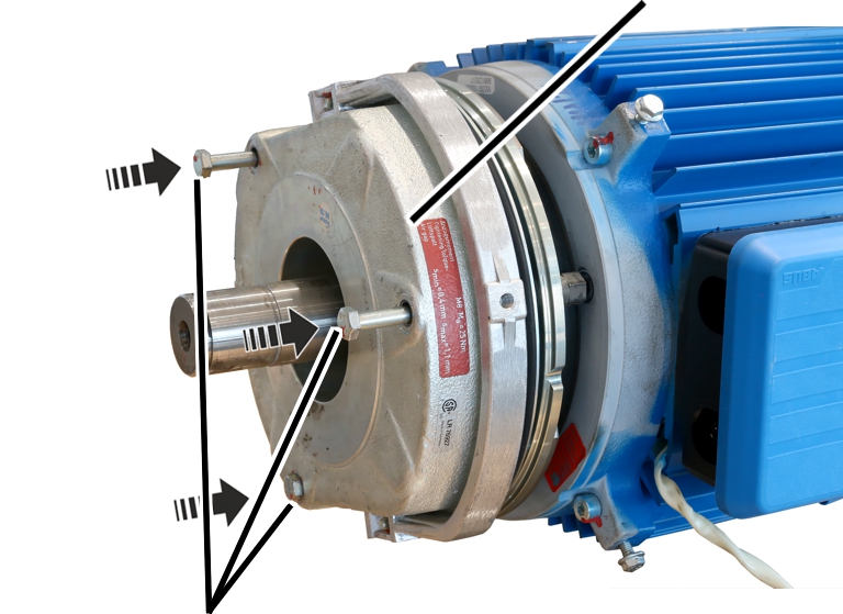
- Slide the magnet body onto the motor shaft.
- Screw on the hexagon head screws (3x).
Hexagon head screw |
Tightening torque |
|---|---|
M6x70 |
10 Nm |
M8x80 |
25 Nm |
M8x90 |
25 Nm |
M8x100 |
25 Nm |
If necessary, replace the hexagon head screws and banjo bolts with new ones.
- Then the air gap must be readjusted. See “Setting the air gap on the brake”.
- Connect the power supply of the magnet body.
Covering the brake
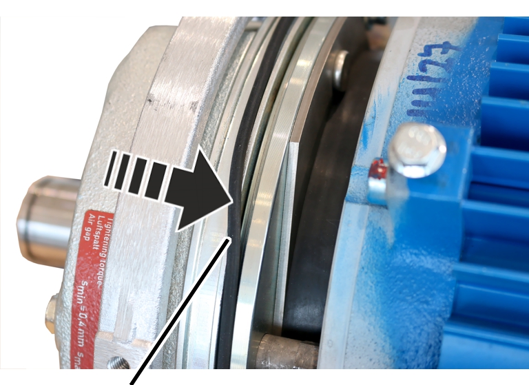
- Insert the O-ring.
Only for fan blades on the motor shaft
Fitting the fan blade
Circlip
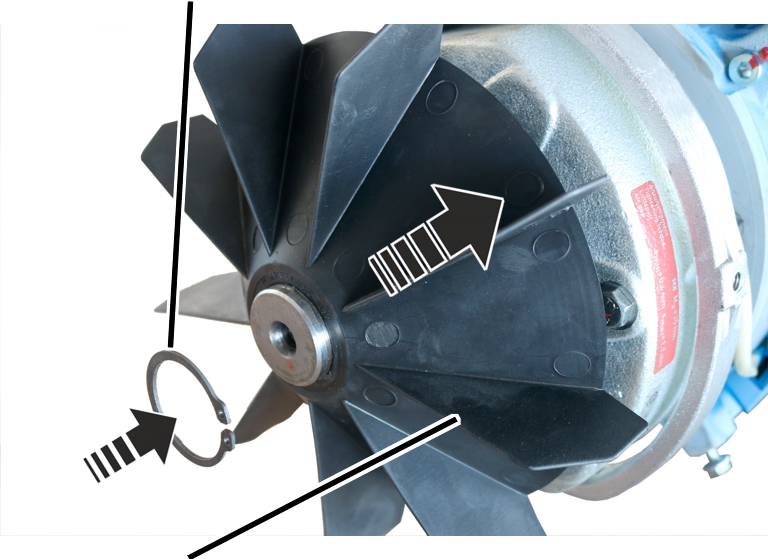
- Insert the fan blade on the motor shaft.
- Insert the circlip.
Only for auxiliary fans without frame
Plug-in connection
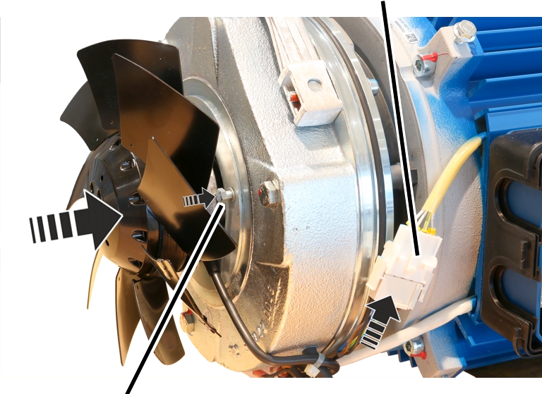
- Place the auxiliary fan on the magnet body.
- Bolt on the auxiliary fan with hexagon head screws M5x10 (3x). 4.8 Nm. Secure with thread-locking compound (medium tightness).
- If necessary: Insert the plug-in connection from the auxiliary fan.
- Check the direction of rotation of the auxiliary fan: The direction of rotation is determined by the rotary field of the auxiliary fan. The air must be drawn in from the direction of the fan cover and blown along the motor. If the rotary field is incorrect, the auxiliary fan will rotate in the wrong direction and the hoist motor will not be cooled sufficiently.
Only for auxiliary fans with frame
Plug-in connection
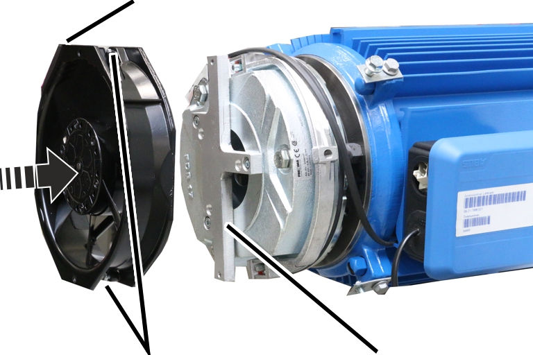
- Place the auxiliary fan on the mount.
- Tighten the auxiliary fan with M4x16 fillister-head screw (2x). 2.4 Nm. Secure with screw locking varnish (medium strength).
- Insert the plug-in connection from the auxiliary fan.
- Check the direction of rotation of the auxiliary fan: The direction of rotation is determined by the orientation in which the auxiliary fan is mounted on the bracket. The air must be drawn in from the direction of the fan cover and blown along the motor. If the direction of rotation is incorrect, the auxiliary fan will rotate in the wrong direction and the hoist motor will not be cooled sufficiently.
Closing the fan cover
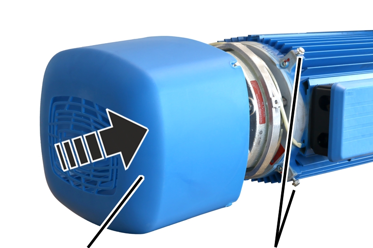
- Attach fan cover.
- Screw in the rib screws (3x) of the fan cover.
Maintenance
This section applies to anyone who maintains, repairs or modifies the crane.
The end user of the crane is responsible for the selection and proper qualifications of the maintenance personnel.
Examples of qualified persons:
- Persons with comprehensive knowledge from specialist training in engineering and in the electrical systems of cranes.
- Persons with sufficient experience in the operation, installation and maintenance of cranes.
- Persons with comprehensive knowledge regarding the relevant technical rules, directives and safety regulations applicable in the respective country.
- Persons receiving regular training from ABUS.
ABUS assumes no liability for damage due to incorrectly performed maintenance work done by unqualified personnel.
ABUS recommends having the maintenance work performed by ABUS Service.
Use only original ABUS replacement parts. Otherwise, all warranty claims will be rendered invalid.
Instructions regarding safety when performing maintenance work
Please follow the following safety instructions during all repair work on the hoist drive:
- Switch off the mains switch. Secure the switch to ensure it cannot be turned back on accidentally.
- Unplug the mains disconnector plug from the socket on the crane panel. Secure the socket with a padlock to ensure it is not plugged back in accidentally.
- Use suitable lifting platforms and fall protection equipment.
- Adequately cordon off the operating range around the lifting platform.
- Switch off any other cranes using the same crane track or cranes working above or below the crane undergoing maintenance. Secure the switches to ensure they cannot be turned back on accidentally. Otherwise, other cranes could overturn the hoisting platform or crash into the crane undergoing maintenance.
- Notify personnel in the area that maintenance work will be performed.
- Only trained electricians should work on the crane electrical system!
- Even after the emergency stop button has been pressed, life-threatening high voltages are still present in the panels.
These safety instructions apply for the hoist drive specifically:
- Do not permanently remove the fan cover with auxiliary fan! If the fan cover is removed, hazardous areas are no longer protected. This can result in persons being injured and the hoist motor can become too hot! Remount the fan cover after working on the hoist drive. Do not permanently remove the fan cover to improve cooling.
- Danger of being crushed or trapped during the assembly! The hoist drive is very heavy. It is therefore not easy to handle during the assembly and can become jammed and tilt. For the assembly, use the ABUS assembly aid AN103574 so that the hoist drive is suspended horizontally.
- Danger from electric shock! Even after the crane has been switched off, life-threatening high voltages are present in the frequency converter and hoist motor. Before working on the hoist drive, detach the connection cable of the hoist motor.
Setting the air gap on the brake
If the air gap is wider than permitted, it must be readjusted.
Overview:
Air gap (between magnet body and anchor plate)Brake lining thickness
Dimension |
Value |
|---|---|
Air gap between anchor plate and magnet body |
Between 0.4 mm and 1.1 mm |
Target value for air gap |
0.4 mm |
Size |
Brake lining thickness (minimum) [mm] |
||
|---|---|---|---|
Hoist motor L6 |
Hoist motor H6 |
Hoist motor U6 |
|
800.4 |
9.3 |
9.3 |
9.3 |
1000.7 |
9.3 |
9.3 |
11.3 |
2000.3 |
9.3 |
11.3 |
- |
3000.4 |
11.3 |
12.3 |
- |
5000.3 |
12.3 |
13.8 |
- |
6000.3 |
13.8 |
- |
- |
7000.1 |
- |
13.8 |
13.8 |
As soon as the hoist motor stops running, the anchor plate presses against the brake rotor through spring force, braking the hoist motor. An air gap is created between the magnet body and the anchor plate. When the hoist motor starts up, the magnet body pulls the anchor plate away from the brake rotor and the hoist motor can rotate freely again.
If the brake lining is worn, the air gap will be larger. See “Inspecting the brake on the hoist drive”. If the air gap is larger than the maximum permitted, the brake must be readjusted. If the brake lining on the brake rotor is worn too thin, it must be replaced. See “Replacing the brake rotor on the hoist drive”.
Taking off the fan cover
- Unscrew the rib screws (3x) of the fan cover.
- Take off the fan cover.
Only for fan blades on the motor shaft
Removing the fan blade
Circlip
- Remove the circlip.
- Remove the fan blade.
Only for auxiliary fans without frame
Plug-in connection
- If present: Unplug the plug-in connection from the auxiliary fan.
- Release the hexagon head screws (3x) on the auxiliary fan and remove the auxiliary fan.
- If the auxiliary fan does not have a plug-in connection: Leave the auxiliary fan connected and secure it on the hoist motor, e.g. with a lashing strap.
Only for auxiliary fans with frame
Plug-in connection
screwMount
- Unplug the plug-in connection from the auxiliary fan.
- Release the fillister-head screws (2x) on the auxiliary fan and remove the auxiliary fan.
Uncovering the brake
- Remove the O-ring.
- Clean the entire brake with compressed air.
Setting the air gap
Magnet bodyBanjo bolt
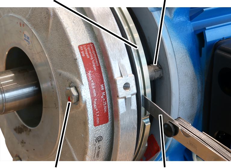
head screwFeeler gauge
- Unscrew the hexagon head screws (3x) by a half turn.
- Screw in the banjo bolts (3x) by a half turn in the direction of the magnet body.
- Read off the set width of the air gap from the table.
Overview:
Air gap (between magnet body and anchor plate)Brake lining thickness
Dimension |
Value |
|---|---|
Air gap between anchor plate and magnet body |
Between 0.4 mm and 1.1 mm |
Target value for air gap |
0.4 mm |
Size |
Brake lining thickness (minimum) [mm] |
||
|---|---|---|---|
Hoist motor L6 |
Hoist motor H6 |
Hoist motor U6 |
|
800.4 |
9.3 |
9.3 |
9.3 |
1000.7 |
9.3 |
9.3 |
11.3 |
2000.3 |
9.3 |
11.3 |
- |
3000.4 |
11.3 |
12.3 |
- |
5000.3 |
12.3 |
13.8 |
- |
6000.3 |
13.8 |
- |
- |
7000.1 |
- |
13.8 |
13.8 |
- Insert the appropriate feeler gauge directly next to one of the hexagon head screws in the air gap between magnet body and anchor plate.
- Tighten the hexagon head screws so that the feeler gauge can still be pulled from the air gap.
- The air gap on this hexagon head screw is now adjusted to the set width.
- Repeat the steps for all hexagon head screws (3x).
Concluding the setting of the air gap
Banjo bolt
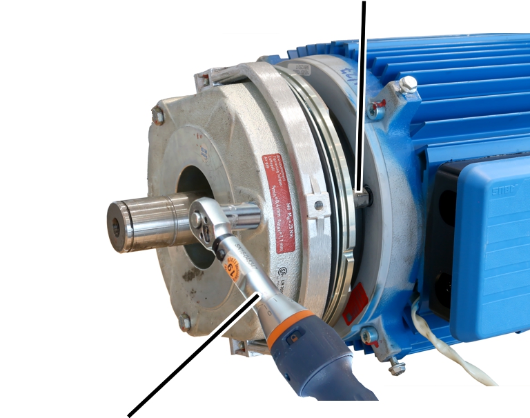
- Screw the banjo bolts (3x) in the direction of the hoist motor until hand-tight.
- Screw on the hexagon head screws (3x).
Hexagon head screw |
Tightening torque |
|---|---|
M6x70 |
10 Nm |
M8x80 |
25 Nm |
M8x90 |
25 Nm |
M8x100 |
25 Nm |
- The brake is fixed with screws.
- Check the air gap next to all three hexagon head screws. If different than the set width, repeat the adjustment.
Covering the brake
- Insert the O-ring.
Only for fan blades on the motor shaft
Fitting the fan blade
Circlip
- Insert the fan blade on the motor shaft.
- Insert the circlip.
Only for auxiliary fans without frame
Plug-in connection
- Place the auxiliary fan on the magnet body.
- Bolt on the auxiliary fan with hexagon head screws M5x10 (3x). 4.8 Nm. Secure with thread-locking compound (medium tightness).
- If necessary: Insert the plug-in connection from the auxiliary fan.
- Check the direction of rotation of the auxiliary fan: The direction of rotation is determined by the rotary field of the auxiliary fan. The air must be drawn in from the direction of the fan cover and blown along the motor. If the rotary field is incorrect, the auxiliary fan will rotate in the wrong direction and the hoist motor will not be cooled sufficiently.
Only for auxiliary fans with frame
Plug-in connection
screw M4x16Mount
- Place the auxiliary fan on the mount.
- Tighten the auxiliary fan with M4x16 fillister-head screw (2x). 2.4 Nm. Secure with screw locking varnish (medium strength).
- Insert the plug-in connection from the auxiliary fan.
- Check the direction of rotation of the auxiliary fan: The direction of rotation is determined by the orientation in which the auxiliary fan is mounted on the bracket. The air must be drawn in from the direction of the fan cover and blown along the motor. If the direction of rotation is incorrect, the auxiliary fan will rotate in the wrong direction and the hoist motor will not be cooled sufficiently.
Closing the fan cover
- Attach fan cover.
- Screw in the rib screws (3x) of the fan cover.
Replacing the brake rotor on the hoist drive
If the brake rotor on the hoist drive is thinner than permitted, the brake rotor must be replaced.
If the anchor plate is also worn and needs to be replaced, the anchor plate can be replaced at the same time.
If additional parts need to be replaced: see “Replacing the entire brake”.
Taking off the fan cover
- Unscrew the rib screws (3x) of the fan cover.
- Take off the fan cover.
Only for fan blades on the motor shaft
Removing the fan blade
Circlip
- Remove the circlip.
- Remove the fan blade.
Only for auxiliary fans without frame
Plug-in connection
- If present: Unplug the plug-in connection from the auxiliary fan.
- Release the hexagon head screws (3x) on the auxiliary fan and remove the auxiliary fan.
- If the auxiliary fan does not have a plug-in connection: Leave the auxiliary fan connected and secure it on the hoist motor, e.g. with a lashing strap.
Only for auxiliary fans with frame
Plug-in connection
screwMount
- Unplug the plug-in connection from the auxiliary fan.
- Release the fillister-head screws (2x) on the auxiliary fan and remove the auxiliary fan.
Uncovering the brake
- Remove the O-ring.
- Clean the entire brake with compressed air.
Disassembling the magnet body
Power supplyMagnet body
- Disconnect the power supply of the magnet body.
- Release the hexagon head screws (3x).
- Pull the magnet body from the motor shaft.
Removing the old brake rotor
Brake rotor
- Pull the brake rotor from the hub and from the motor shaft.
Removing the circlip and front feather key
If the anchor plate needs to be replaced:
Front feather keyCirclip
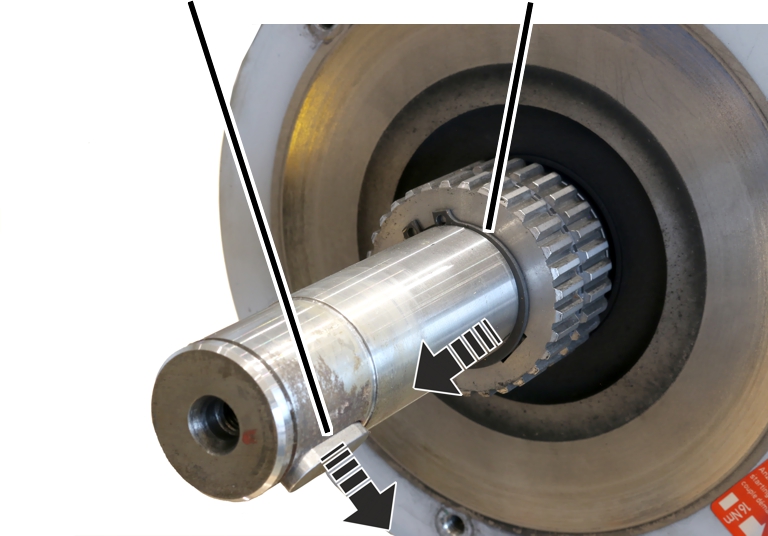
- Remove the front feather key.
- Remove the circlip.
Removing hub and rear feather key
If the anchor plate needs to be replaced:
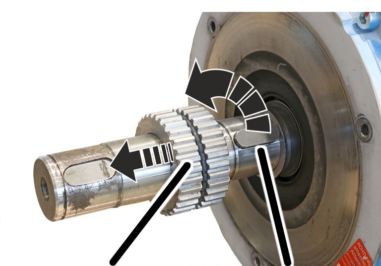
- Pull the hub from the motor shaft.
- The brake is completely disassembled.
- Remove the rear feather key.
Installing rear feather key and hub
If the anchor plate needs to be replaced:
Hub
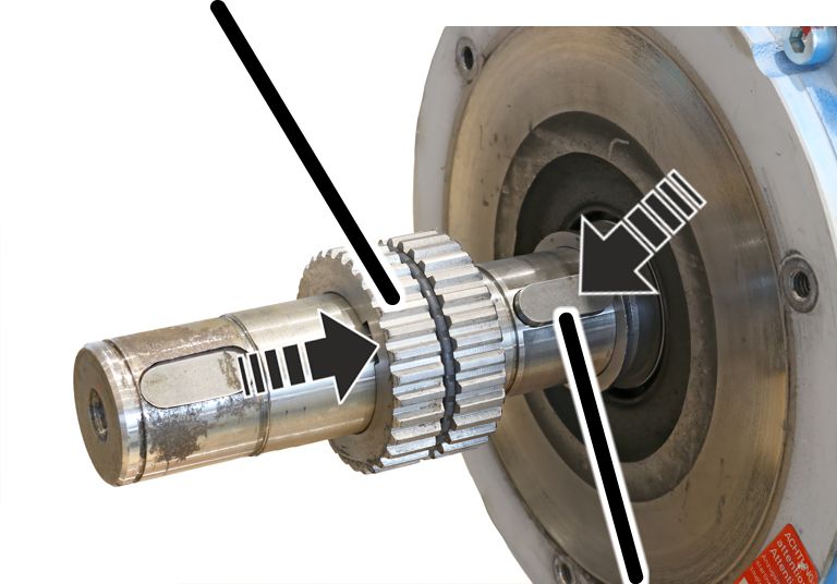
- Insert the new rear feather key.
- Slide the new hub over the rear feather key onto the motor shaft.
Inserting front feather key and new circlip
If the anchor plate needs to be replaced:
Front feather keyCirclip
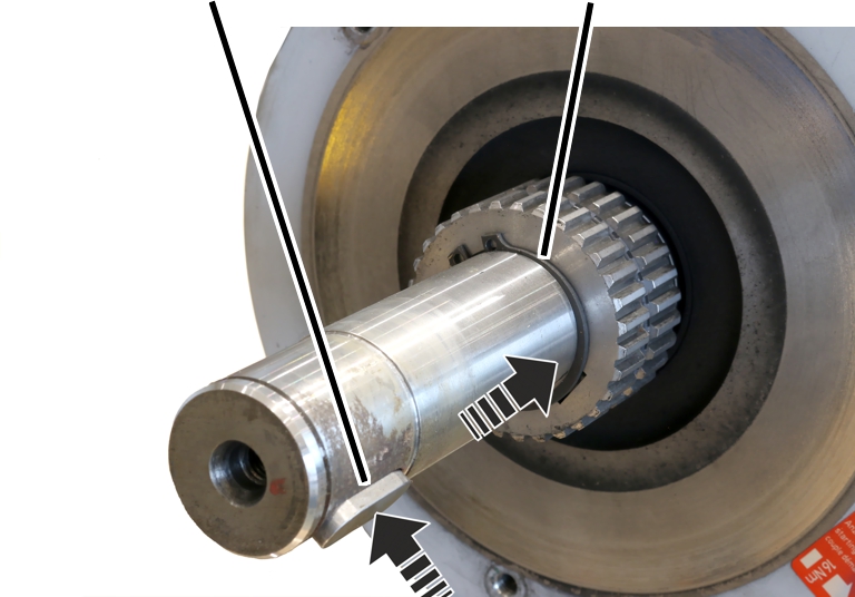
- Insert the new circlip.
- Insert the front feather key.
Installing the new brake rotor
Hub
- If present: Check whether the O-ring lies fully in the groove of the hub.
- Slide the brake rotor over the motor shaft onto the hub.
Removing the old anchor plate
If the anchor plate needs to be replaced:
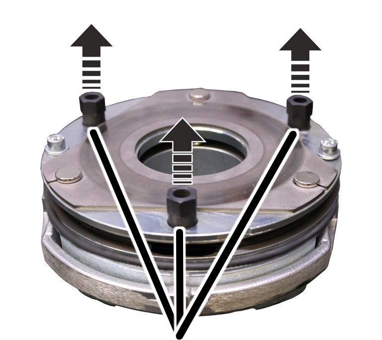
- Unscrew the banjo bolts (3x).
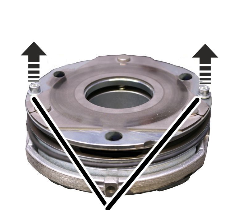
- Unscrew the hoist brake air gap adjustment screws (2x) with washers (2x) and compression springs (2x).
O-ring
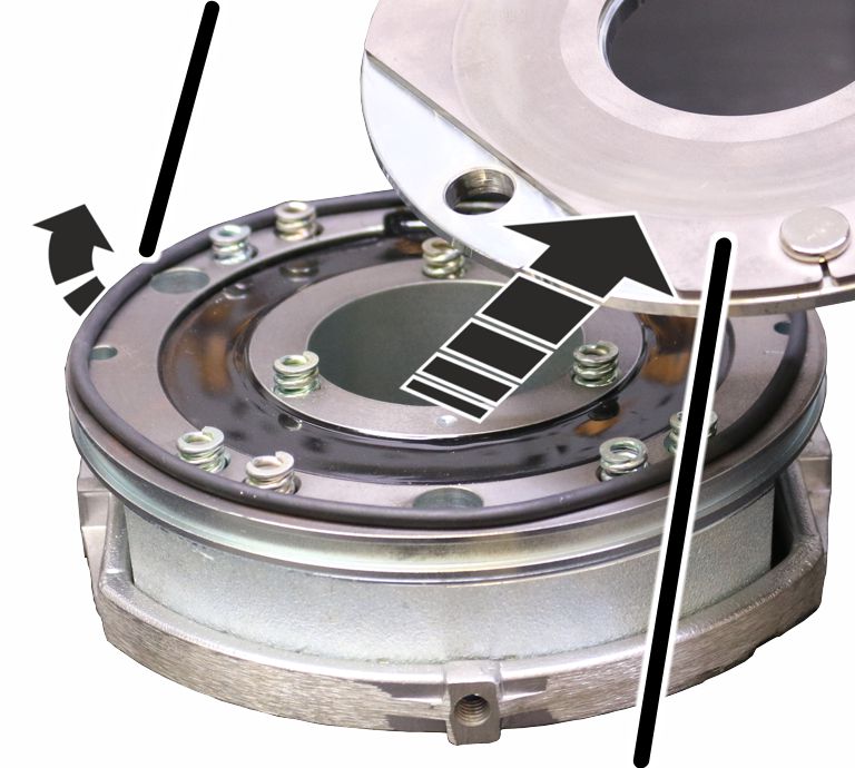
- Remove the anchor plate.
- Remove the exposed O-ring from the groove.
Tension bolt
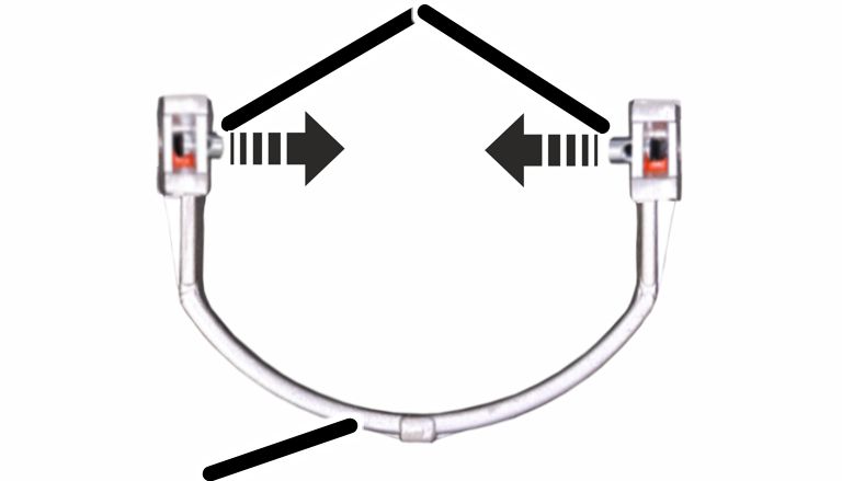
- Remove the tension bolts (2x) from the brake release lever.
- Clean the brake release lever from the inside.
Installing the new anchor plate
If the anchor plate needs to be replaced:
Tension bolt
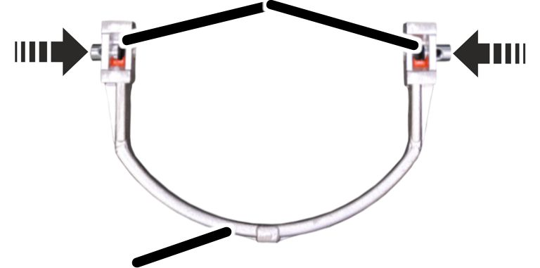
- Insert new tension bolts (2x) into the brake release lever.
Turn the tension bolts so that the hoist brake air gap adjustment screw (2x) can engage in the tension bolts.
O-ringAnchor plate
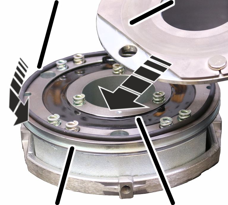
- Insert the new O-ring into the groove on the magnet body.
- Place the new anchor plate on the magnet body.
Brake
release leverAnchor
plate
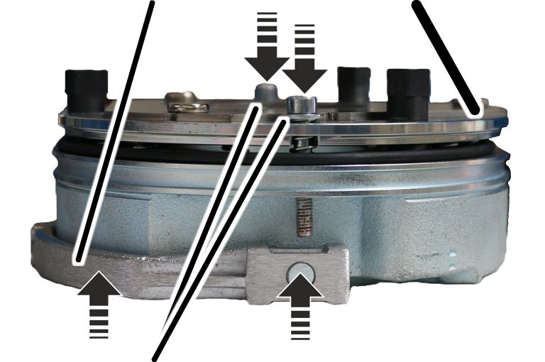
- Insert new hoist brake air gap adjustment screws (2x) with washers (2x) and compression springs (2x) into the anchor plate.
- Screw the brake release lever securely in place using the hoist brake air gap adjustment screws (2x).
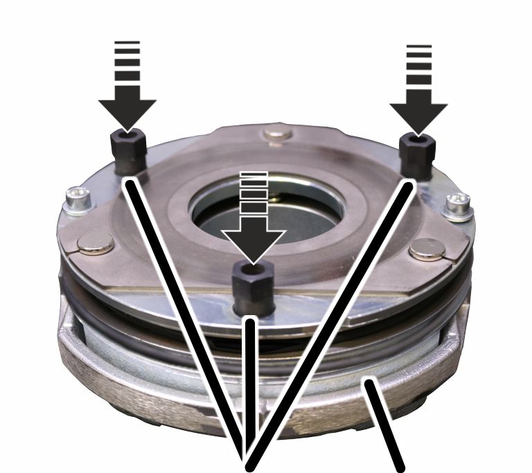
boltsMagnet
body
- Screw the anchor plate onto the magnet body by hand using new banjo bolts (3x).
Air gap
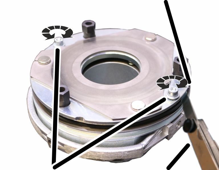
air gap
adjustment screwsFeeler
gauge
- Insert the feeler gauge next to the hoist brake air gap adjustment screws into the air gap between the anchor plate and the magnet body and measure the distance.
- Adjust the air gap to 1.1 mm using the hoist brake air gap adjustment screws (2x).
Mounting the magnet body
Magnet body
- Slide the magnet body onto the motor shaft.
- Screw the hexagon head screws (3x) hand-tight.
If included in the spare parts kit, replace hexagon head screws and banjo bolts with new screws.
- Connect the power supply of the magnet body.
Setting the air gap
Magnet bodyBanjo bolt
head screwFeeler gauge
- Unscrew the hexagon head screws (3x) by a half turn.
- Screw in the banjo bolts (3x) by a half turn in the direction of the magnet body.
- Read off the set width of the air gap from the table.
Overview:
Air gap (between magnet body and anchor plate)Brake lining
thickness
with brake lining
Dimension |
Value |
|---|---|
Air gap between anchor plate and magnet body |
Between 0.4 mm and 1.1 mm |
Target value for air gap |
0.4 mm |
Size |
Brake lining thickness (minimum) [mm] |
||
|---|---|---|---|
Hoist motor L6 |
Hoist motor H6 |
Hoist motor U6 |
|
800.4 |
9.3 |
9.3 |
9.3 |
1000.7 |
9.3 |
9.3 |
11.3 |
2000.3 |
9.3 |
11.3 |
- |
3000.4 |
11.3 |
12.3 |
- |
5000.3 |
12.3 |
13.8 |
- |
6000.3 |
13.8 |
- |
- |
7000.1 |
- |
13.8 |
13.8 |
- Insert the appropriate feeler gauge directly next to one of the hexagon head screws in the air gap between magnet body and anchor plate.
- Tighten the hexagon head screws so that the feeler gauge can still be pulled from the air gap.
- The air gap on this hexagon head screw is now adjusted to the set width.
- Repeat the steps for all hexagon head screws (3x).
Concluding the setting of the air gap
Banjo bolt
- Screw the banjo bolts (3x) in the direction of the hoist motor until hand-tight.
- Screw on the hexagon head screws (3x).
Hexagon head screw |
Tightening torque |
|---|---|
M6x70 |
10 Nm |
M8x80 |
25 Nm |
M8x90 |
25 Nm |
M8x100 |
25 Nm |
- The brake is fixed with screws.
- Check the air gap next to all three hexagon head screws. If different than the set width, repeat the adjustment.
Covering the brake
- Insert the O-ring.
Only for fan blades on the motor shaft
Fitting the fan blade
Circlip
- Insert the fan blade on the motor shaft.
- Insert the circlip.
Only for auxiliary fans without frame
Plug-in connection
- Place the auxiliary fan on the magnet body.
- Bolt on the auxiliary fan with hexagon head screws M5x10 (3x). 4.8 Nm. Secure with thread-locking compound (medium tightness).
- If necessary: Insert the plug-in connection from the auxiliary fan.
- Check the direction of rotation of the auxiliary fan: The direction of rotation is determined by the rotary field of the auxiliary fan. The air must be drawn in from the direction of the fan cover and blown along the motor. If the rotary field is incorrect, the auxiliary fan will rotate in the wrong direction and the hoist motor will not be cooled sufficiently.
Only for auxiliary fans with frame
Plug-in connection
screw M4x16Mount
- Place the auxiliary fan on the mount.
- Tighten the auxiliary fan with M4x16 fillister-head screw (2x). 2.4 Nm. Secure with screw locking varnish (medium strength).
- Insert the plug-in connection from the auxiliary fan.
- Check the direction of rotation of the auxiliary fan: The direction of rotation is determined by the orientation in which the auxiliary fan is mounted on the bracket. The air must be drawn in from the direction of the fan cover and blown along the motor. If the direction of rotation is incorrect, the auxiliary fan will rotate in the wrong direction and the hoist motor will not be cooled sufficiently.
Closing the fan cover
- Attach fan cover.
- Screw in the rib screws (3x) of the fan cover.
Replacing the entire brake
If the brake rotor is thinner than permitted, the brake may not be readjusted again. In this case, the brake rotor must be replaced.
Depending on wear and necessity, additional parts of the brake may need to be replaced.
- Friction disc
- Hub
- O-ring
- Banjo bolts
- Feather key
- Circlip
- Magnet body
Taking off the fan cover
- Unscrew the rib screws (3x) of the fan cover.
- Take off the fan cover.
Only for fan blades on the motor shaft
Removing the fan blade
Circlip
- Remove the circlip.
- Remove the fan blade.
Only for auxiliary fans without frame
Plug-in connection
head screw
- If present: Unplug the plug-in connection from the auxiliary fan.
- Release the hexagon head screws (3x) on the auxiliary fan and remove the auxiliary fan.
- If the auxiliary fan does not have a plug-in connection: Leave the auxiliary fan connected and secure it on the hoist motor, e.g. with a lashing strap.
Only for auxiliary fans with frame
Plug-in connection
screwMount
- Unplug the plug-in connection from the auxiliary fan.
- Release the fillister-head screws (2x) on the auxiliary fan and remove the auxiliary fan.
Uncovering the brake
- Remove the O-ring.
- Clean the entire brake with compressed air.
Disassembling the magnet body
Power supplyMagnet body
- Disconnect the power supply of the magnet body.
- Release the hexagon head screws (3x).
- Pull the magnet body from the motor shaft.
Pulling off the brake rotor
Brake rotor
- Pull the brake rotor from the hub and from the motor shaft.
Removing the circlip and the feather key
Feather keyCirclip
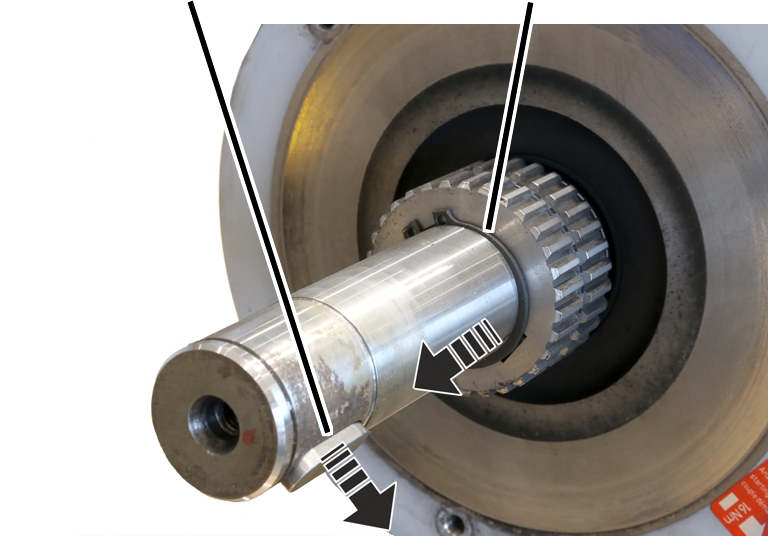
- Remove the feather key.
- Remove the circlip.
Removing the hub
HubRear feather key
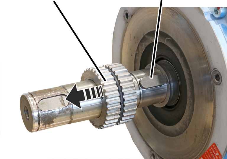
- Pull the hub from the motor shaft.
- The brake is completely disassembled.
Inserting the new hub
HubRear feather key
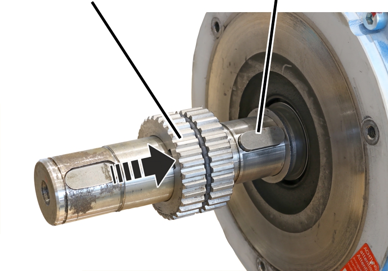
- Slide the new hub over the rear feather key onto the motor shaft.
Inserting the circlip
Feather keyCirclip
- Insert the circlip.
- Insert the front feather key.
Installing the brake rotor
Hub
- If present: Check whether the O-ring lies fully in the groove of the hub.
- Slide the brake rotor over the motor shaft onto the hub.
Mounting the magnet body
Magnet body
- Slide the magnet body onto the motor shaft.
- Screw the hexagon head screws (3x) hand-tight.
If included in the spare parts kit, replace hexagon head screws and banjo bolts with new screws.
- Connect the power supply of the magnet body.
Setting the air gap
Magnet bodyBanjo bolt
- Unscrew the hexagon head screws (3x) by a half turn.
- Screw in the banjo bolts (3x) by a half turn in the direction of the magnet body.
- Read off the set width of the air gap from the table.
Overview:
Air gap (between magnet body and anchor plate)Brake lining thickness
Dimension |
Value |
|---|---|
Air gap between anchor plate and magnet body |
Between 0.4 mm and 1.1 mm |
Target value for air gap |
0.4 mm |
Size |
Brake lining thickness (minimum) [mm] |
||
|---|---|---|---|
Hoist motor L6 |
Hoist motor H6 |
Hoist motor U6 |
|
800.4 |
9.3 |
9.3 |
9.3 |
1000.7 |
9.3 |
9.3 |
11.3 |
2000.3 |
9.3 |
11.3 |
- |
3000.4 |
11.3 |
12.3 |
- |
5000.3 |
12.3 |
13.8 |
- |
6000.3 |
13.8 |
- |
- |
7000.1 |
- |
13.8 |
13.8 |
- Insert the appropriate feeler gauge directly next to one of the hexagon head screws in the air gap between magnet body and anchor plate.
- Tighten the hexagon head screws so that the feeler gauge can still be pulled from the air gap.
- The air gap on this hexagon head screw is now adjusted to the set width.
- Repeat the steps for all hexagon head screws (3x).
Concluding the setting of the air gap
Banjo bolt
- Screw the banjo bolts (3x) in the direction of the hoist motor until hand-tight.
- Screw on the hexagon head screws (3x).
Hexagon head screw |
Tightening torque |
|---|---|
M6x70 |
10 Nm |
M8x80 |
25 Nm |
M8x90 |
25 Nm |
M8x100 |
25 Nm |
- The brake is fixed with screws.
- Check the air gap next to all three hexagon head screws. If different than the set width, repeat the adjustment.
Covering the brake
- Insert the O-ring.
Only for fan blades on the motor shaft
Fitting the fan blade
Circlip
- Insert the fan blade on the motor shaft.
- Insert the circlip.
Only for auxiliary fans without frame
Plug-in connection
head screw M5x10
- Place the auxiliary fan on the magnet body.
- Bolt on the auxiliary fan with hexagon head screws M5x10 (3x). 4.8 Nm. Secure with thread-locking compound (medium tightness).
- If necessary: Insert the plug-in connection from the auxiliary fan.
- Check the direction of rotation of the auxiliary fan: The direction of rotation is determined by the rotary field of the auxiliary fan. The air must be drawn in from the direction of the fan cover and blown along the motor. If the rotary field is incorrect, the auxiliary fan will rotate in the wrong direction and the hoist motor will not be cooled sufficiently.
Only for auxiliary fans with frame
Plug-in connection
- Place the auxiliary fan on the mount.
- Tighten the auxiliary fan with M4x16 fillister-head screw (2x). 2.4 Nm. Secure with screw locking varnish (medium strength).
- Insert the plug-in connection from the auxiliary fan.
- Check the direction of rotation of the auxiliary fan: The direction of rotation is determined by the orientation in which the auxiliary fan is mounted on the bracket. The air must be drawn in from the direction of the fan cover and blown along the motor. If the direction of rotation is incorrect, the auxiliary fan will rotate in the wrong direction and the hoist motor will not be cooled sufficiently.
Closing the fan cover
- Attach fan cover.
- Screw in the rib screws (3x) of the fan cover.
Replacing the hoist motor on the hoist drive
If there is a defect, the hoist motor can be disassembled from the gear unit and replaced individually. Because of the modular construction, the gear unit does not need to be disassembled.
The images show the replacement on a GM 6000 hoist drive. The replacement of a hoist motor in a different size does not essentially differ.
Selecting the installation option
Preferred option: Hoist motor vertically disassembled toward the top:
The safest option is disassembly of the hoist motor vertically toward the top from a hoist drive that is lying down. For this, the hoist drive must first be disassembled from the wire rope hoist. This option should preferably be selected when possible.
- Disassemble the hoist drive. See "Installing the hoist drive", page 8.
- Turn the hoist drive and lay it on the gear unit.
Alternatively: Support the hoist motor horizontally from below:
The hoist motor can be replaced horizontally if the hoist drive is mounted on the wire rope hoist. Depending on the accessibility on the wire rope hoist, the hoist motor may need to be supported from below, e.g. with a suitable forklift.
During replacement, the hoist motor must be secured so that the weight can be safely held.
Alternatively: Secure the hoist motor horizontally from above:
Depending on the installation situation, the hoist motor can also be replaced horizontally while being held from above. For this, a movable slinging point is attached in the housing of the hoist motor. Since the cable drum housing is located directly above the hoist motor, the slinging point is usually not easily accessible.
Disassembling the hoist motor
The images show the replacement on a vertically positioned hoist drive.
- Unscrew the rib screws (3x) of the fan cover.
- Take off the fan cover.
Eyebolt with lifting tackleHoist motor
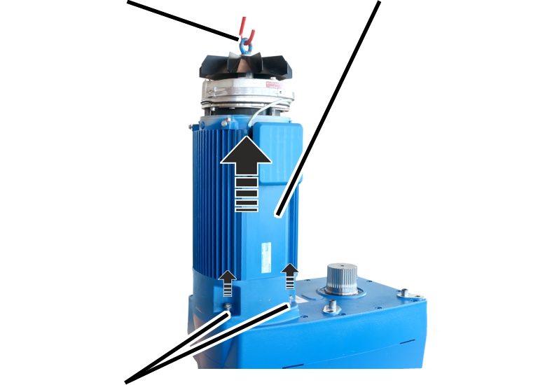
- Only with fan blades on the motor shaft: Screw a suitable eyebolt into the motor shaft and sling suitable lifting tackle in the eyebolt.
- Only with auxiliary fans: Disassemble auxiliary fan and screw an eyebolt into the motor shaft.
If no eyebolt can be screwed into the motor shaft: Use suitable lifting tackle with which the hoist motor can be lifted vertically.
- Release the rib screws (4x).
- Lift the hoist motor.
- The coupling halves between hoist motor and hoisting gear slide apart.
- The hoist motor is disassembled.
Installing the hoist motor
The images show the replacement on a vertically positioned hoist drive.
Coupling halves
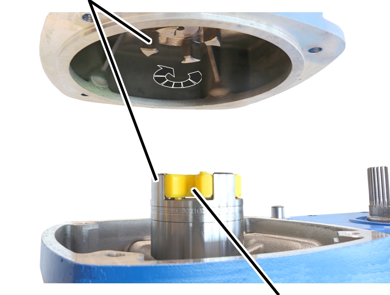
- Bring the hoist motor over the hoisting gear.
- Turn the hoist motor so that the connector housing faces the exterior of the subsequently mounted hoist drive.
- Insert the coupling star on the coupling half on the hoisting gear.
- Turn the coupling halves on the hoisting gear so that the coupling halves from the hoist motor and from the hoisting gear lie exactly over one another and mesh into each other during the assembly.
In the case of a removed hoist drive, the coupling half on the gear unit can be turned.
- Insert the hoist motor on the hoisting gear.
- The coupling halves slide into each other in the coupling star.
- Tighten the rib screws (4x) on the hoist motor.
Size |
Size and length |
Tightening torque |
|---|---|---|
GM800.4 |
M8x25 |
35 Nm |
GM1000.6 |
M8x25 |
35 Nm |
GM2000.3 |
M8x25 |
35 Nm |
GM3000.4 |
M10x30 |
50 Nm |
GM5000.3 |
M10x30 |
50 Nm |
GM6000.4 |
M10x30 |
50 Nm |
GM7000.1 |
M10x30 |
50 Nm |
Lowering the load by hand in an emergency (emergency lowering)
In the event of a power failure, a defective hoist motor or a defective brake coil, the load can be lowered by hand. To do so, the brake is released manually using the brake release lever.
Lowering a load by hand is an emergency measure.
Securing the operating range
- Cordon off the operating range around the crane sufficiently.
- Inform persons around the crane about the emergency lowering procedure.
Removing the fan cover
- Unscrew the rib screws (3x) of the fan cover.
- Take off the fan cover.
Lowering a load
Brake release leverThreaded
rod
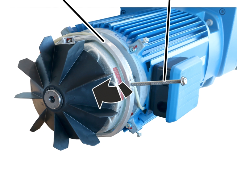
- Screw an M6 or M8 threaded rod into the brake release lever.
- Carefully and slowly tilt the brake release lever backwards with the threaded rod.
- The brake is released, the load slips downwards.
Braking the load:
- Let go of the brake release lever if the load is dropping too quickly.
- The brake release lever tilts back, the load is braked.
Replacing the brake
The brake lining is subject to a heavy load during emergency lowering and can quickly overheat. The brake lining must therefore be replaced afterwards. See "Replacing the brake rotor on the hoist drive".
Lubricants
Note:
Synthetic lubricants may not be mixed with mineral-based lubricants!
Hoisting gear GM 800
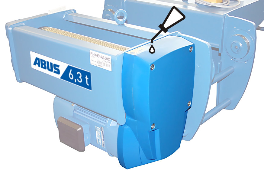
Lubrication ex works using lubricant with the standard designation “SAE POW-90 DIN 51502”.
Quantity: 1500 ml
Alternatively: use lubricant with the standard designation “CLP ISO VG 680 DIN 51502”
- The hoisting gear is lubricated for its entire service life.
This applies with an average daily hoist running time of less than one hour with a medium or limited load spectrum.
At the end of its service life (in a general overhaul), assess whether the lubricant needs to be changed.
Hoisting gear GM 1000
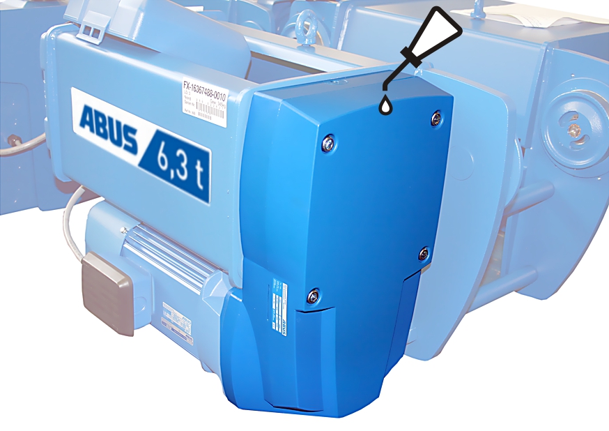
Lubrication ex works using lubricant with the standard designation “CLP ISO VG 680 DIN 51502”
Quantity: 1600 ml
- The hoisting gear is lubricated for its entire service life.
This applies with an average daily hoist running time of less than one hour with a medium or limited load spectrum.
At the end of its service life (in a general overhaul), assess whether the lubricant needs to be changed.
Hoisting gear GM 2000
Lubrication ex works using lubricant with the standard designation “CLP ISO VG 320 DIN 51502”
Quantity: 500 ml
Alternatively: use lubricant with the standard designation “CLP ISO VG 680 DIN 51502”
- The hoisting gear is lubricated for its entire service life.
This applies with an average daily hoist running time of less than one hour with a medium or limited load spectrum.
At the end of its service life (in a general overhaul), assess whether the lubricant needs to be changed.
Hoisting gear GM 3000
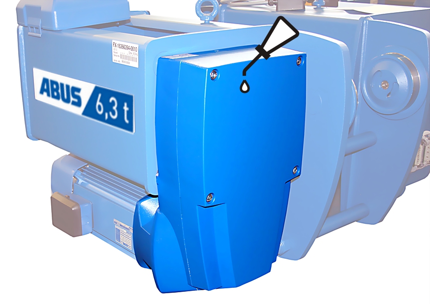
Lubrication ex works using lubricant with the standard designation “CLP ISO VG 320 DIN 51502”
Quantity: 800 ml
Alternatively: use lubricant with the standard designation “CLP ISO VG 680 DIN 51502”
- The hoisting gear is lubricated for its entire service life.
This applies with an average daily hoist running time of less than one hour with a medium or limited load spectrum.
At the end of its service life (in a general overhaul), assess whether the lubricant needs to be changed.
Hoisting gear GM 5000
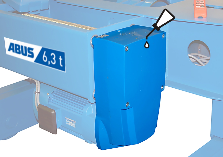
Lubrication ex works using lubricant with the standard designation “SAE 80W-90 DIN 51502”.
Quantity: 4000 ml
Alternatively: use lubricant with the standard designation “CLP ISO VG 680 DIN 51502”
- The hoisting gear is lubricated for its entire service life.
This applies with an average daily hoist running time of less than one hour with a medium or limited load spectrum.
At the end of its service life (in a general overhaul), assess whether the lubricant needs to be changed.
Hoisting gear GM 6000
Lubrication ex works using lubricant with the standard designation “CLP ISO VG 320 DIN 51502”
Quantity: 11200 ml
Alternatively: use lubricant with the standard designation “CLP ISO VG 680 DIN 51502”
- The hoisting gear is lubricated for its entire service life.
This applies with an average daily hoist running time of less than one hour with a medium or limited load spectrum.
At the end of its service life (in a general overhaul), assess whether the lubricant needs to be changed.
Hoisting gear GM 7000
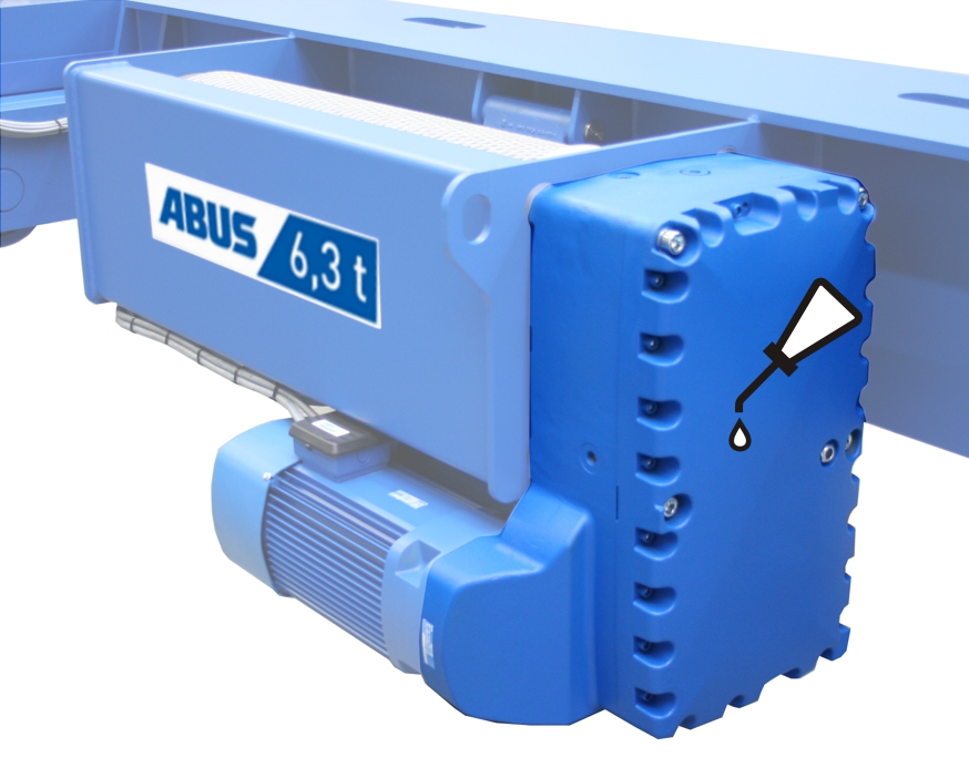
Lubrication ex works using lubricant with the standard designation “CLP ISO VG 680 DIN 51502”
Quantity GM 7000: 27000 ml
- The hoisting gear is lubricated for its entire service life.
This applies with an average daily hoist running time of less than one hour with a medium or limited load spectrum.
At the end of its service life (in a general overhaul), assess whether the lubricant needs to be changed.
Lubricant repository in the cable drum
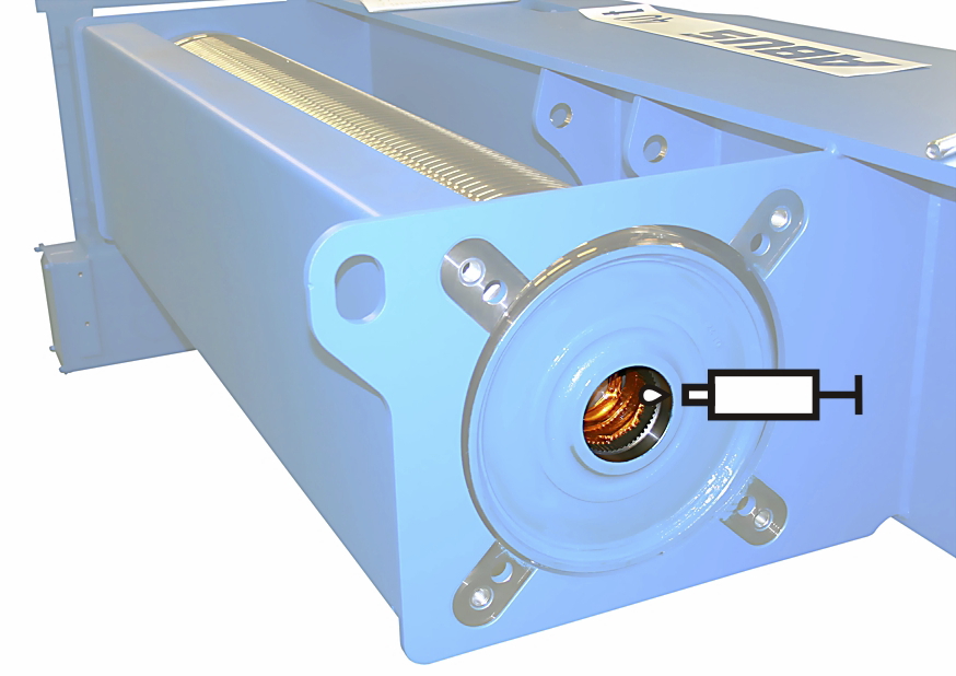
Lubricated at factory with "high temperature paste PBC 1574" item number 303678.
Quantity GM 800: 25 g
Quantity GM 1000: 25 g
Quantity GM 2000: 50 g
Quantity GM 3000: 50 g
Quantity GM 5000: 70 to 75 g
Quantity GM 6000: 70 to 75 g
Quantity GM 7000: 70 to 75 g
- Fill the lubricant repository (behind the gearing):
- When the hoisting gear is disassembled and reassembled
- When carrying out a general overhaul.
- After 10 years at the latest
The specification of 10 years applies to single-shift operation with an average daily hoist running time of less than one hour with a medium or limited load spectrum. If the hoist is used more intensively or the operating conditions are more difficult (e.g. multiple-shift operation, higher ambient temperature, aggressive environmental conditions), shorter intervals will be necessary.
Gearing in the cable drum
Lubricated at factory with high temperature paste PBC 1574 item number 6758.
Quantity: Apply lubricant with brush to coat surface completely.
- Lubricate the gearing in the cable drum:
- When the hoisting gear is disassembled and reassembled
- When carrying out a general overhaul.
- After 10 years at the latest
The specification of 10 years applies to single-shift operation with an average daily hoist running time of less than one hour with a medium or limited load spectrum. If the hoist is used more intensively or the operating conditions are more difficult (e.g. multiple-shift operation, higher ambient temperature, aggressive environmental conditions), shorter intervals will be necessary.
Gearing on output shaft on the hoisting gear,
pins on the hoisting gear
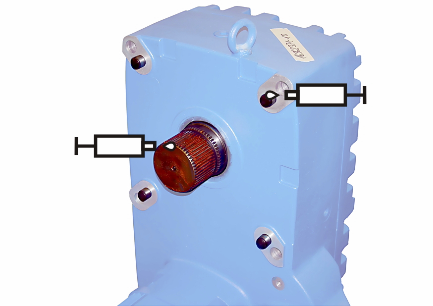
Lubricated at factory with high temperature paste PBC 1574 item number 6758.
Quantity: Apply lubricant with brush to coat surface completely.
- Lubricate pins:
- When the hoisting gear is disassembled and reassembled
- Lubricate the gearing on the output shaft:
- When the hoisting gear is disassembled and reassembled
- When carrying out a general overhaul.
- After 10 years at the latest
The specification of 10 years applies to single-shift operation with an average daily hoist running time of less than one hour with a medium or limited load spectrum. If the hoist is used more intensively or the operating conditions are more difficult (e.g. multiple-shift operation, higher ambient temperature, aggressive environmental conditions), shorter intervals will be necessary.
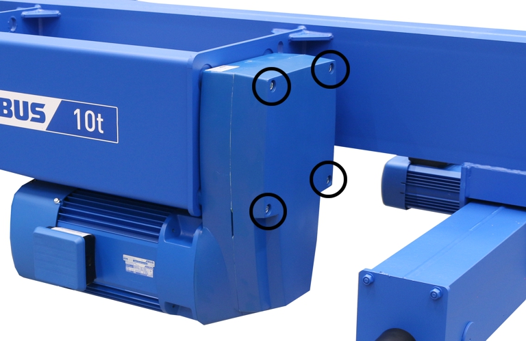
Overview of screw tightening torques
Hoist Drive GM 800 to 7000
Size |
Type, size and length |
Number |
Tightening torque |
|---|---|---|---|
GM800.4 |
Fillister-head screw M10x110 |
4x |
40 Nm |
GM1000.6 |
Fillister-head screw M12x120 |
4x |
85 Nm |
GM2000.3 |
Fillister-head screw M12x120 |
4x |
85 Nm |
GM3000.4 |
Fillister-head screw M12x160 |
4x |
85 Nm |
GM5000.3 |
Fillister-head screw M16x210 |
4x |
210 Nm |
GM6000.4 |
Fillister-head screw M16x220 |
4x |
210 Nm |
GM7000.1 |
Fillister-head screw M20x270 |
4x |
425 Nm |
Hoist motor
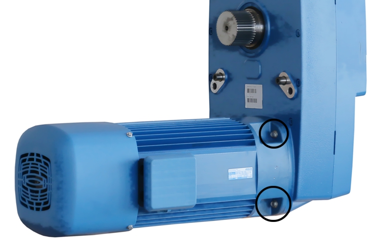
Size |
Size and length |
Number |
Tightening torque |
|---|---|---|---|
GM800.4 |
Rib screw M8x25 |
4x |
35 Nm |
GM1000.6 |
Rib screw M8x25 |
4x |
35 Nm |
GM2000.3 |
Rib screw M8x25 |
4x |
35 Nm |
GM3000.4 |
Rib screw M10x30 |
4x |
50 Nm |
GM5000.3 |
Rib screw M10x30 |
4x |
50 Nm |
GM6000.4 |
Rib screw M10x30 |
4x |
50 Nm |
GM7000.1 |
Rib screw M10x30 |
4x |
50 Nm |